US5485662A - Apparatus and method for crimping fiber for nonwoven applications - Google Patents
Apparatus and method for crimping fiber for nonwoven applications Download PDFInfo
- Publication number
- US5485662A US5485662A US08/235,306 US23530694A US5485662A US 5485662 A US5485662 A US 5485662A US 23530694 A US23530694 A US 23530694A US 5485662 A US5485662 A US 5485662A
- Authority
- US
- United States
- Prior art keywords
- doctor blade
- stuffer box
- fiber
- cooling
- crimper
- Prior art date
- Legal status (The legal status is an assumption and is not a legal conclusion. Google has not performed a legal analysis and makes no representation as to the accuracy of the status listed.)
- Expired - Fee Related
Links
Images


Classifications
-
- D—TEXTILES; PAPER
- D02—YARNS; MECHANICAL FINISHING OF YARNS OR ROPES; WARPING OR BEAMING
- D02G—CRIMPING OR CURLING FIBRES, FILAMENTS, THREADS, OR YARNS; YARNS OR THREADS
- D02G1/00—Producing crimped or curled fibres, filaments, yarns, or threads, giving them latent characteristics
- D02G1/12—Producing crimped or curled fibres, filaments, yarns, or threads, giving them latent characteristics using stuffer boxes
Definitions
- the present invention relates to crimping equipment used in the manufacturing of fibers, especially polyolefin fibers, and a process for crimping fibers. Further, this invention relates to fibers for nonwoven applications, especially polyolefin fibers such as polypropylene fibers.
- Crimpers are used in processing fibers to add bulkiness, cohesiveness, and cardability.
- a crimper works by having two driven rolls pinch the tow and force it into a confined space, known as a stuffer box.
- the stuffer box includes two doctor blades positioned close to the driven rollers, and side plates. Crimping occurs because the filaments are forced against a cake of more slowly moving filaments.
- heat in the form of steam, has been used ahead of the crimper to soften the filaments prior to crimping. Additionally, heat, also in the form of steam, is fed through holes in the doctor blades into the stuffer box to lubricate the tow.
- McGill Modern Crimping Techniques, Fiber World, pp.
- the doctor blades can be positioned at a variety of angles in relationship to the driven rolls. Further, McGill discloses that the top doctor blade may be hinged, and that the driven rolls may be hollow in order to circulate temperature-control fluids.
- U.S. Pat. No. 4,620,345, to Fleissner discloses an apparatus for crimping including a pair of delivery rolls, a stuffer box, a chute following an outlet of the stuffer box for supplying the crimped fiber to a sieve drum for setting the crimp, with the sieve drum being traversed by cooling air.
- This invention relates to an apparatus for crimping fiber without fusing the filaments.
- the invention relates to the stuffer box of a crimper.
- Stuffer boxes are preferably composed of doctor blades and side plates.
- the present invention preferably provides cooling in both the wear tip and trailing portions of the stuffer box enabling cooling throughout the stuffer box, while preventing the filaments from sticking together and reducing burnishing damage to the filaments and the filament crimp.
- a crimper for crimping fiber comprising a stuffer box comprising a first doctor blade; a second doctor blade opposing said first doctor blade; and means for feeding fiber into the stuffer box.
- means for cooling the stuffer box can include means for directly cooling the stuffer box so as to indirectly cool fiber passing through said stuffer box.
- these means can include means for directly cooling the stuffer box with a chilled cooling medium so as to indirectly cool fiber passing through the stuffer box, or means for directly cooling the stuffer box with a liquid cooling medium so as to indirectly cool fiber passing through the stuffer box.
- the means for cooling can comprise means for cooling the stuffer box with a cooling medium, such as a liquid cooling medium, either in direct or indirect contact with either or both blades.
- Each of the first doctor blade and the second doctor blade can comprise a wear tip portion and a trailing portion, and the means for directly cooling the stuffer box so as to indirectly cool fiber can be positioned at the trailing portion of one or both of the doctor blades.
- the means for directly cooling the stuffer box so as to indirectly cool fiber can comprise at least one internal compartment for flow of cooling fluid in at least one of, or in both of, the first doctor blade and the second doctor blade.
- the internal compartment can comprise a plurality of compartments, either separate or connected by passages.
- At least one of the wear tip portions, or both of the wear tip portions, of the first doctor blade and the second doctor blade can comprise means for cooling, such as at least one internal passage including a plurality of exit apertures to inject a fluid into the stuffer box.
- each of the first doctor blade and the second doctor blade can comprise separate portions or can be of one-piece construction.
- the first doctor blade and the second doctor blade can further comprise a main body including at least one internal passage connected with the at least one internal passage in the at least one wear tip portion; at least one internal passage for supplying cooling fluid to the at least one internal compartment; and at least one internal passage for removing cooling fluid from the at least one internal compartment.
- the trailing portion of at least one of the first doctor blade and the second doctor blade can further comprise at least one internal passage including a plurality of exit apertures to direct a fluid into the stuffer box.
- the crimper can comprise opposing side plates, as well as means for connecting the doctor blade to the two opposing side plates.
- the means for connecting can comprise adjustable connecting means for adjusting the doctor blade to the opposing side plates.
- the first doctor blade and the second doctor blade can be adjustably positioned opposing each other at a distance between about 15 mm and 60 mm.
- one of the doctor blades is adjustable by the dimensioning and construction thereof.
- either of the two doctors blades can be the doctor blade that is connected to the adjustable connecting means so as to be adjustably positioned, or the doctor blade that is adjustable by dimensioning and construction thereof.
- the crimper can comprise means for applying pressure within the stuffer box; the two opposing side plates can further comprise inserts positioned opposing the driven rolls and the means for feeding fiber can comprise driven rolls.
- the first doctor blade and the second doctor blade can be positioned from the driven rolls at a distance between about 0.001 inch and 0.020 inch, and the driven rolls can be spaced apart a distance of about 0.004 inch to 0.006 inch.
- the present invention is directed to a crimper for crimping fiber, comprising a stuffer box comprising a first doctor blade comprising a wear tip portion and a trailing portion; a second doctor blade opposing the first doctor blade comprising a wear tip portion and a trailing portion; two opposing side plates; means for feeding fiber into said stuffer box; each said trailing portion of the first doctor blade and the second doctor blade comprising at least one internal compartment for flow of cooling liquid within each respective trailing portion; and each said wear tip portion of the first doctor blade and the second doctor blade comprising at least one internal passage including a plurality of exit apertures to inject a fluid into the stuffer box.
- the present invention is also directed to process for crimping fiber comprising heating the fiber; feeding the heated fiber, at a rate capable of crimping the fiber, into a stuffer box having a first doctor blade, a second doctor blade opposing said first doctor blade, and two opposing side plates; and cooling the fiber as the fiber passes through the stuffer box with a cooling fluid which directly cools the stuffer box and indirectly cools the fiber, or with a cooling fluid, such as a liquid, which indirectly contacts the stuffer box and the fibers.
- the means for cooling of the trailing portion of the first and second doctor blades can comprise at least one internal compartment, and the cooling can comprise circulating cooling fluid, such as a liquid or a chilled cooling medium, including a chilled liquid, within the at least one internal compartment of the first and second doctor blades.
- the heating step of the process can further comprise applying steam, preferably between about 0 and 40 psi.
- the process can include providing the wear tip portions of the first and second doctor blades with at least one internal passage including a plurality of exit apertures, and applying air through the plurality of exit apertures.
- the cooling fluid in the internal compartments can be at a temperature between about 5° C. and 40° C.
- the compressed air can have a temperature between about 5° C. and 40° C.
- the heating step of the process can comprise applying steam, preferably between about 0 and 40 psi.
- the trailing portions of the first and second doctor blades further comprise at least one internal passage including a plurality of exit apertures, and the process can further comprise applying air through the plurality of exit apertures in the trailing portion, preferably at a pressure between about 0.5 and 15 psi.
- the process can further comprise applying pressure within the stuffer box; the temperature of the fiber entering the stuffer box can be between about 120° F. and 200° F.; and the temperature of the fiber leaving the stuffer box can be between about 130 and 180° F.
- a process for crimping fiber which enables control of crimping by adjusting temperature conditions, can comprise heating the fiber; feeding the heated fiber, at a rate capable of crimping the fiber, into a stuffer box comprising a first doctor blade comprising a wear tip portion and a trailing portion; a second doctor blade opposing the first doctor blade comprising a wear tip portion and a trailing portion; two opposing side plates; each said trailing portion of the first doctor blade and the second doctor blade comprising at least one internal compartment for flow of liquid within each respective trailing portion; and each said wear tip portion of the first doctor blade and the second doctor blade comprising at least one internal passage including a plurality of exit apertures to inject a fluid into the stuffer box; controlling at least one of flow rate and temperature of a liquid flowing through the internal compartment in each of the first doctor blade and the second doctor blade; and controlling at least one of flow rate and temperature of the fluid being injected into
- a still further embodiment of the present invention is to provide a fiber made by the process according to the present invention.
- the fiber is a polyolefin. More preferably, the polyolefin is selected from the group consisting of polypropylene, polyethylene, or mixtures thereof. Even more preferably, the polyolefin is polypropylene.
- the fiber may include about 10-50 crimps per inch.
- the present invention comprises a doctor blade including a wear tip portion; and a trailing portion including means for internal cooling.
- the means for cooling comprises at least one internal compartment for flow of cooling fluid, such as a liquid such as water.
- the wear tip portion of the doctor blade comprises at least one internal passage including a plurality of exit apertures.
- the at least one internal compartment for flow of cooling fluid comprises a plurality of internal compartments, preferably connected through at least one flow passage, and the trailing portion further comprises at least one internal passage including a plurality of exit apertures.
- the cooling effects of the present invention allow use of more heat before the crimper for better crimp formation.
- the cooling fluid, such as air, at the wear tip portion tends to keep the filaments from sticking together and provides lubrication.
- the cooling compartment in the trailing portion such as a water-cooled compartment, reduces burnishing damage to the filaments and to the filament crimp, and tends to set the crimp against pull-out. Adjustment of the cooling fluid at the wear tip portion and cooling provided by the cooling compartment in the trailing portion yields improved flexibility and control of product properties, including crimp and average cohesion, and enables the obtaining of a fiber that can be thermal bonded into a non-woven fabric possessing high uniformity.
- the wear tip is a separate part of the doctor blade with internal ducts for compressed air to be piped through for injection under and above the tow cake, as it slides through the stuffer box.
- the air cools, softens, and helps the crimped tow cake slide through the trailing section of the stuffer box.
- the trailing section of the doctor blades have smooth surfaces, preferably without openings, and internal compartments for water cooling to lower overall temperatures to reduce burnishing/fusion and to set the crimp before tension is applied to carry the tow to the next process step.
- the invention provides significant improvement in crimpability.
- the crimpability improvement relates directly to fibers with improved cohesion.
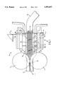
- FIG. 1 is a cross-sectional, schematic view of the crimper assembly according to the present invention
- FIG. 2 is a top view of the main body of the top doctor blade according to the present invention.
- FIG. 3 is a cross-sectional view taken along line 3--3 in FIG. 2.
- FIG. 4 is a rear view of the main body of the top doctor blade.
- FIG. 5 is a top view of the trailing portion of the top doctor blade according to the present invention.
- FIG. 6 is a cross-sectional view taken along line 6--6 in FIG. 5.
- FIG. 7 is a top view of the trailing portion of the top doctor blade according to a further embodiment of the present invention.
- FIG. 8 is a bottom view of the wear tip of the top doctor blade according to the present invention.
- FIG. 9 is cross-sectional view taken along line 9--9 in FIG. 8.
- doctor blade refers to elements associated with the stuffer box through which the filaments to be crimped are driven, such as an upper plate and a lower plate, or left and right plates, associated with the stuffer box.
- the doctor blade can include, as part of the plate, a portion that ensures the directing of the filaments from the driven rolls into the stuffer box.
- the portion that ensures the directing of the filaments into the stuffer box can be a portion separate from the plates.
- the term “doctor blade” will collectively refer to the plate separate from the portion that directs the filaments into the stuffer box and to the plate including the portion that directs the filaments into the stuffer box.
- direct cooling refers to direct contact between the cooling fluid or liquid and the material being cooled
- indirect cooling refers to the cooling fluid or liquid not being in direct contact with the material being cooled.
- direct cooling of fibers includes contact of the cooling fluid with the fibers
- indirect cooling of fibers includes cooling without any contact of the cooling fluid or liquid with the fibers.
- the crimper 8 includes driven crimper rolls 1 that pinch the tow 2 to pull it toward the stuffer box 10 and to push the tow into the stuffer box 10.
- the clearance between the driven rolls can be between about 0.001 inch and 0.006 inch, preferably between about 0.004 inch and 0.006 inch.
- the stuffer box 10 includes a top doctor blade 3, a bottom doctor blade 4 and side plates 5, which define a space 34 in which the fiber is crimped.
- Pressure known as flapper pressure
- flapper pressure is applied within the stuffer box 10 by pressurizing the top doctor blade 3 with a mechanism for applying pressure 6.
- Such mechanism for applying pressure to the top doctor blade 3 may be any pressure means known in the art, and can, for example, include an air cylinder to provide pressure.
- Both doctor blades 3 and 4 fit closely to the driven crimper rolls 1 to guide the tow 2 into the stuffer box 10 and prevent the tow 2 from wrapping around the rolls 1.
- the clearance between the doctor blades 3 and 4 and the driven rolls 1 is between about 0.001 and 0.020 inch, preferably between about 0.014 inch and 0.016 inch.
- the distance between the top doctor blade 3 and the bottom doctor blade 4 is between about 15 mm and 60 mm, preferably between about 40 mm and 60 mm.
- FIG. 1 illustrates the adjustable attachment means 7 for the bottom doctor blade 4.
- the bottom doctor blade 4 is attached to the side plates 5 by adjustable attachment elements 7.
- the top doctor blade 3 adjustable by the dimensioning and construction thereof.
- the adjustable attachment elements 7, which, for example, include bolts 40 and slots 41 in side plates 5, enables the distance between the top and the bottom doctor blades 3 and 4 to be changed, as well as changing the clearance between the doctor blades and the driven rolls 1, depending upon the type of fiber being crimped and the amount of crimp desired.
- the slots are angled to accommodate the horizontal movement needed to maintain the distance between the doctor blade and the driven crimper rolls 1 as the vertical distance between the doctor blades is changed.
- the crimper also includes intermediate plates 9 positioned next to the top bottom doctor blade 3 and the bottom doctor blade 4. Guide plates 11 are positioned next to the intermediate plates 9. The thickness of the intermediate plate 9 can also be changed to accommodate the adjustment of the distance between the top and bottom doctor blades.
- the side plates 5 are indented at the point where the driven rolls 1 pinch the tow 2. Rotating circular brass or bronze inserts 30 are positioned in the indentations to prevent the tow 2 from being pushed out the sides of the driven rolls 1.
- the difference in the high speed of the driven crimper rolls 1 and the slow take-away of the tow from the back end of the stuffer box 10 causes the tow to cake.
- the filaments buckle or crimp against the cake inside the stuffer box 10.
- An exit chute 12 is positioned at the end of the crimper 10 to guide the crimped tow 13 away from the crimper.
- the top and bottom doctor blades include a main body 42, a wear tip portion 14 and a trailing portion 15.
- the top doctor blade is shown in detail in FIGS. 2-9.
- the bottom doctor blade is preferably substantially identical to the top doctor blade, and so as to not be unduly duplicative, the figures of drawings of the bottom doctor blade are not illustrated. However, any discussion and/or illustration of the top doctor blade can also be considered to be a discussion and/or illustration of the bottom doctor blade.
- the main body 42 of the top doctor blade 3 is shown in FIGS. 2-4.
- the trailing portion 15 is shown in detail in FIGS. 5 and 6.
- the wear tip section 14 is shown in detail in FIGS. 8 and 9.
- the wear tip portion 14 and the trailing portion 15 are both connected to the main body by connection means, such as a plurality of bolts 48, shown schematically in FIG. 1.
- the main body of the top doctor blade includes passageways for feeding compressed air to the wear tip section and cooling fluid to and from the trailing portion.
- the compressed air enters the top doctor blade 3 through entrance opening 26 and travels through the main body of the doctor blade 3 by way of internal passage 25, which connects with the at least one internal passage 18a which in turn connects with open space 18b.
- open space 18b extends over substantially the entire height of the main body 42.
- the open space is made by any method known in the art. In one preferred method the space is drilled through the main body and cap 18d is placed over the space.
- the open space 18b connects with at least one internal passage 18 in the wear tip section 14 through at least one lower portion 18c, as shown in FIG. 9.
- the number of internal passages both for supplying the compressed air to the wear tip section and within the wear tip section may be changed depending upon the amount of air desired. Further, the pattern in which the internal passages are connected and the number of exit apertures may also be varied.
- wear tip section 14 includes at least one internal passage 18 which is used for the application of compressed air into the stuffer box 10 by way of a plurality of exit apertures 19, which are shown in FIG. 8.
- the at least one internal passage 18 in wear tip section 14 and the at least one internal passage 18a in main body 42 are made by any manner known in the art. One preferred way is by drilling internal passages 18 through the width of the wear tip section. As shown in FIGS. 2 and 8, plugs 33 are inserted into the drilled internal passages 18 to prevent the compressed air from leaking out the ends.
- the compressed air cools the tow cake from above and below as it slides through the stuffer box 10.
- the air cools, softens, and helps the crimped tow cake slide through the trailing section of the stuffer box 10.
- main body 42 includes means for feeding cooling fluid, such as a chilled cooling fluid, a liquid, a chilled liquid, preferably, water or cooled water, into and out of the trailing portion 15 of the top doctor blade.
- the cooling fluid is fed through the at least one internal compartment 20, to provide further cooling of the tow 2 within the stuffer box 10.
- the cooling fluid enters the main body 42 of the doctor blade through entrance opening 22, flows through at least one entrance flow passage 22a and at least one entrance flow tube 22b into internal compartment 20 of the trailing portion 15.
- the cooling fluid is removed from the internal compartment 20 by at least one exit flow tube 27b, and at least one exit flow passage 27a and out of at least one exit 27.
- the trailing portion can have a plurality of internal compartments 20 each of which, as shown in FIG. 2, can be connected to the main body by a plurality of entrance tubes 22b and a plurality of exit flow tubes 27b. Additionally, the internal compartments 20 can be connected by at least one flow passage 23, as shown in FIGS. 5 and 6. The shape, number and connection of the internal compartments, as well as the number of inlets and outlets for the cooling fluid can be varied.
- the cooling of the doctor blades is achieved by directly cooling the doctor blade by circulating liquid, such as water, through an internally located compartment
- other means for cooling can be used.
- any means that can indirectly cool the fiber passing through the stuffer box can be used, even if these means indirectly cool the doctor blade.
- the means for cooling can comprise a compartment or conduit external to the doctor blade with a fluid, such as a gas or liquid, passing therethrough, which indirectly cools the doctor blade and also achieves indirect cooling of the fibers.
- any means that can lower the temperature of the doctor blade, while indirectly cooling the fibers would be within the scope of present invention.
- FIG. 4 is a rear view of the main body 15 of the top doctor blade 3, which as described above, includes an entrance opening 26 for compressed air, an entrance opening 22 for cooling fluid and at least one exit 27 for removal of cooling fluid.
- the trailing portion 15 of the top doctor blade 3 includes at least one internal compartment 20 for the circulation of a cooling fluid, and at least one internal passage 34, including a plurality of exit apertures 21, for flow of compressed air therethrough.
- the number and pattern of the internal passages for circulation of cooling fluid and compressed air, as well as the number of exit apertures can be varied. This embodiment enables the provision of compressed air at both the wear tip and trailing portions of the doctor blade.
- the process of crimping fiber begins by heating the tow prior to the crimper.
- steam is applied in a steam chest upstream of the crimper at a pressure between about 0 and 40 psi, preferably between about 0 and 10 psi.
- the steam chest is hinged and can be operated in an open position which allows for the application of no steam.
- the steam chest can also be operated in the closed position with or without steam being applied.
- As the tow enters the crimper its temperature is between about 120° F. and 200° F., preferably between about 150° F. and 200° F.
- Flapper pressure is applied in the stuffer box at between about 2 and 10 bars, preferably between about 5 and 8 bars. Compressed air is fed to the doctor blades at a gauge pressure between about 0.5 to 15.0 psi, preferably about 3.0 to 5.0 psi.
- the compressed air enters the crimper through a plurality of apertures in the wear tips of the doctor blades.
- a cooling fluid specifically water
- the temperature of the tow is reduced by as much as 20° F. to 30° F.
- the temperature of the fiber leaving the stuffer box is between about 90° F. and 180° F.
- the specific steam pressure, flapper pressure, air pressure and temperature of the cooling fluid used in the crimping process may vary depending upon the properties desired in the product. For example, applying pre-crimper steam adds heat to allow the fiber to be crimped easier. The application of higher air pressure results in a softer fiber that flows through the apparatus easier. Increased flapper pressure reduces the flow through the apparatus and increases the crimps per inch. Further, increased flapper pressure increases the contact of the tow with the apparatus and thereby improves the cooling to reduce the fusion between the filaments and set the crimp. A set crimp reduces the possibility that the crimp will pull out during further processing.
- compressed air is fed into the stuffer box both through apertures in the wear tip portion of the doctor blade and through apertures in the trailing portion of the doctor blade.
- the compressed air may be fed through both the wear tip and trailing portions at about room temperature of about 70° F. to 80° F.
- the compressed air may be fed at a temperature between about 5° C. and 40° C.
- the air can be treated by a dryer to remove excess moisture and control its relative humidity prior to being fed into the crimper.
- the cooling effects of the invention allows use of more heat before the crimper for better crimp.
- the mechanical energy added to cause crimping and to force the tow through the stuffer box converts to heat energy causing an increase in tow temperatures of about 20° F. to 40° F. in the crimper.
- the cooling effects of the present invention offset this heat in the area immediately following the crimping action thereby allowing use of more heat before the crimper for better crimp formation.
- Temperatures of the tow entering the crimper have been successfully elevated by about 20 to 50° F. without significant levels of fusion between filaments of the tow. The air cools, softens, and tends to keep filaments from sticking together.
- the invention is illustrated in the following nonlimiting examples.
- the fiber is treated with a finish in a manner known in the art to adjust the hydrophobic/hydrophilic properties of the fiber.
- Hydrophilic polypropylene was produced using an apparatus and method according to the present invention. Specifically, the apparatus used in Tests 1-8 fed compressed air at room temperature through 147 holes in the wear tip section of the doctor blades. Each hole was 3/64 inch in diameter. Cooling water was circulated through two compartments in the trailing section. The water entered through one entrance passage and exited through two exit passages. The distance between the top and bottom doctor blade was 30 mm. The distance between the driven rolls was 0.001 inch and the distance between the doctor blades and driven rolls was 0.014 inch.
- Comparative Example 1 also used steam before the crimper and compressed air in the crimper, but did not use cooling fluid in the trailing portion.
- the crimper used for the comparative example had 460 holes with a 3/64 inch diameter in each doctor blade including 3 rows of ten holes in the wear tip portion and 7 rows of ten holes in the trailing portion.
- the distance between the driven rolls was 0.001 inch and the distance between the doctor blades and driven rolls was 0.014 inch.
- the tow was fed into the driven rolls at 225 meters per minute.
- Table I The processing variables and results of these tests are summarized in Table I.
- the water temperature used for tests 1-8 was not measured. However, the inventor believes the temperature to be approximately 50° F. to 55° F.
- the flapper pressure for each of the comparative examples in tests 1-8 was not measured, however it was maintained constant and is believed to be approximately 6 psi for the comparative example and tests 1-8.
- the other processing variables listed in Table I are: temperature of the tow before the steam is applied, after the steam is applied and after the tow has been crimped, as well as the air pressure within the crimper and the steam pressure within the steam box before the crimper.
- Fabric was made from each of the fibers in tests 1-8.
- the fabric was made on a small thermal bonding process line known to one of ordinary skill in the art,
- the line has prefeeders and openers to pull apart the large chunks of fiber from the compacted bale into small clumps to pass through feeds and stock transfer fans onto one or more roller-topped cards (up to four) where the fibers are spread, randomized and doffed onto a conveyor for transporting the layers of spread fibers to the calender.
- Calendering involved passing the spread layers of fiber between two heated rolls that are pressed together. One of the rolls is embossed with a diamond pattern having a land area of approximately 19%, and the other is smooth.
- the fabric was measured using a fabric formation test wherein the fabric is viewed with a video camera.
- the image signal is digitized and analyzed for white reflectance and blackness distribution over the sample area as a measure of fabric uniformity.
- the results of the fabric measurement are listed in Table I as percent white; the standard deviation of the percent white; the percent thin, which is the amount of the black area measured in the fabric; the percent black in a 27 mm square portion of fabric; and the percent black in a 2.2 mm square portion of fabric.
- the fabric was tested to determine its maximum cross-directional strength, which measures the amount of force required to pull apart a one-inch by five-inch portion of fabric.
- Table I includes the maximum temperature, which is the temperature of the thermal bonding of fabric that produced the maximum cross-directional strength.
- the crimp, measured in crimps per inch (cpi), and cohesion of the fiber produced in Tests 1-8 was significantly improved over the fiber produced in the comparative example at the same flapper pressure. Additionally, the uniformity of fabric made with the fiber produced according to the present invention was improved. Specifically, fabric made from the fiber produced in Tests 1 and 2 showed improved white reflectance (percent white) and a reduction in the amount of black area (percent thin). These results indicate that the fibers produced using an apparatus and method according to the present invention produce improved fabric.
- Hydrophobic polypropylene was produced using an apparatus and method according to the present invention.
- the apparatus used for the comparative example and the test examples were the same as the apparatus used in the comparative example and test examples of Example 1.
- Tests 9-19 were run with steam before the driven rolls, and cooling within the stuffer box.
- Comparative Example 2 was run with steam before the driven rolls and air in the crimper.
- the tow was fed into the driven rolls at 225 meters per minute.
- Table II The processing variables and results of these tests are summarized in Table II, which includes all of the variables and results shown in Table I, as well as the standard deviation of the crimp and a second measurement for leg, open angle and relaxed length/stretched length.
- the apparatus according to the present invention is capable of producing fiber with significantly higher crimp and cohesion at slightly lower flapper pressure (Test 9), as well as fiber with slightly higher crimp and cohesion at dramatically lower flapper pressure (Test 10).
- the measurement of cohesion for Tests 11-13 and 17-19 exceeded the range of the test equipment which reads a maximum cohesion of 8 grams/grain.
- the 20 psi steam pressure used for Tests 10, 11, 14 and 19 had previously been considered to be unusable because it would lead to fusion of the fibers. However, these tests produced satisfactory crimp.
- Example 3 illustrates the effect of the temperature of the cooling water on the production of hydrophilic polypropylene fiber.
- the apparatus used was the same as the apparatus used in Example 1.
- the tow was fed into the driven rolls at 235 meters per minute.
- Tests 20-27 were run at the same flapper pressure.
- Tests 20-23 were run using water at 20° C.
- Tests 24-27 were run using water at 8° C.
- Table III The test conditions and results are summarized in Table III. The results include two measurements of crimp that were taken from two portions of the fiber and the coefficient of variance of the crimp.
- the apparatus and process is capable of producing fiber with variable levels of cohesion at approximately the same level of crimp.
- Tests 28-38 were run at lower flapper pressure.
- the test results from Example 3 indicate better correlations at the higher flapper pressure.
- higher flapper pressure produced improved results for crimp formation indicators such as crimp angle, percent noncrimp and relaxed length/stretched length.
- colder water produced improved cohesion without significant change in crimps per inch.
- higher flapper pressure produced better correlations for crimp formation, both higher and lower flapper pressure produced fibers that yielded improved fabric uniformity.
- Percent noncrimp may be more a measure of burnishing--which is a phenomena wherein the bend portions of the fiber nearest the doctor blades are rubbed under pressure by the heated surfaces thereby creating a polished portion--than the amount of crimp.
- the highest noncrimp levels occurred at highest flapper pressure and precrimp steam.
Landscapes
- Engineering & Computer Science (AREA)
- Mechanical Engineering (AREA)
- Textile Engineering (AREA)
- Yarns And Mechanical Finishing Of Yarns Or Ropes (AREA)
- Treatment Of Fiber Materials (AREA)
Priority Applications (9)
| Application Number | Priority Date | Filing Date | Title |
|---|---|---|---|
| US08/235,306 US5485662A (en) | 1994-04-29 | 1994-04-29 | Apparatus and method for crimping fiber for nonwoven applications |
| CA002133187A CA2133187C (en) | 1994-04-29 | 1994-09-28 | Apparatus and method for crimping fiber for non-woven applications |
| IL11254895A IL112548A (en) | 1994-04-29 | 1995-02-06 | Fiber curling device and method |
| MXPA95001080A MXPA95001080A (es) | 1994-04-29 | 1995-02-22 | Aparato y metodo para rizar fibras para aplicaciones de materiales no tejidos. |
| DE69531755T DE69531755T2 (de) | 1994-04-29 | 1995-03-15 | Vorrichtung und Verfahren zum Kräuseln von Fasern zur Verwendung in der Herstellung von Vliesstoffen |
| DK95301703T DK0679743T3 (da) | 1994-04-29 | 1995-03-15 | Indretning og fremgangsmåde til krusning af fibre til fremstilling af ikke-vævet stof |
| EP95301703A EP0679743B1 (de) | 1994-04-29 | 1995-03-15 | Vorrichtung und Verfahren zum Kräuseln von Fasern zur Verwendung in der Herstellung von Vliesstoffen |
| CN95105438A CN1048050C (zh) | 1994-04-29 | 1995-04-28 | 非织造布用纤维卷曲设备 |
| CN98118859A CN1080335C (zh) | 1994-04-29 | 1998-08-31 | 卷曲纤维的方法 |
Applications Claiming Priority (1)
| Application Number | Priority Date | Filing Date | Title |
|---|---|---|---|
| US08/235,306 US5485662A (en) | 1994-04-29 | 1994-04-29 | Apparatus and method for crimping fiber for nonwoven applications |
Publications (1)
| Publication Number | Publication Date |
|---|---|
| US5485662A true US5485662A (en) | 1996-01-23 |
Family
ID=22884951
Family Applications (1)
| Application Number | Title | Priority Date | Filing Date |
|---|---|---|---|
| US08/235,306 Expired - Fee Related US5485662A (en) | 1994-04-29 | 1994-04-29 | Apparatus and method for crimping fiber for nonwoven applications |
Country Status (8)
| Country | Link |
|---|---|
| US (1) | US5485662A (de) |
| EP (1) | EP0679743B1 (de) |
| CN (2) | CN1048050C (de) |
| CA (1) | CA2133187C (de) |
| DE (1) | DE69531755T2 (de) |
| DK (1) | DK0679743T3 (de) |
| IL (1) | IL112548A (de) |
| MX (1) | MXPA95001080A (de) |
Cited By (14)
| Publication number | Priority date | Publication date | Assignee | Title |
|---|---|---|---|---|
| US5638842A (en) * | 1994-05-09 | 1997-06-17 | Ricoh Company, Ltd. | Device for removing a film-like image forming substance from a recording medium |
| US5647109A (en) * | 1995-09-26 | 1997-07-15 | American Suessen Corporation | Yarn texturing device including a stuffer box channel with circumferetially closed cross section |
| US5948334A (en) * | 1997-07-31 | 1999-09-07 | Fiberco, Inc. | Compact long spin system |
| US6134758A (en) * | 1999-03-22 | 2000-10-24 | Wellman, Inc. | Method of producing improved crimped polyester fibers |
| US6351877B1 (en) * | 2000-05-31 | 2002-03-05 | Eastman Chemical Company | Synthetic fiber crimper, method of crimping and crimped fiber produced therefrom |
| US6433890B1 (en) | 1998-09-24 | 2002-08-13 | Mdc Max Daetwyler Ag | System and method for improving printing of a leading edge of an image in a gravure printing process |
| US6572966B1 (en) | 1999-03-22 | 2003-06-03 | Wellman, Inc. | Polyester fibers having substantially uniform primary and secondary crimps |
| US20030115729A1 (en) * | 2001-12-21 | 2003-06-26 | Philippe Massotte | Apparatus and method for producing frieze yarns |
| US20030213270A1 (en) * | 2002-05-17 | 2003-11-20 | Rhyne Jeffrey Todd | Heat setting machine with sealing head |
| US20040237211A1 (en) * | 2001-07-03 | 2004-12-02 | Mathias Stundl | Device for compression crimping |
| CN103305987B (zh) * | 2013-06-28 | 2015-11-18 | 昆明醋酸纤维有限公司 | 一种醋酸纤维生产纺丝中的卷曲机 |
| US10271999B2 (en) | 2014-11-06 | 2019-04-30 | The Procter & Gamble Company | Crimped fiber spunbond nonwoven webs/laminate |
| US11135103B2 (en) | 2014-11-06 | 2021-10-05 | The Procter & Gamble Company | Apertured webs and methods for making the same |
| US11213436B2 (en) | 2017-02-16 | 2022-01-04 | The Procter & Gamble Company | Substrates having repeating patterns of apertures for absorbent articles |
Families Citing this family (5)
| Publication number | Priority date | Publication date | Assignee | Title |
|---|---|---|---|---|
| DE602008005706D1 (de) | 2008-03-03 | 2011-05-05 | M A E S P A | Vorrichtung zum Kräuseln von Chemiefaserfäden und Steuerverfahren |
| CN101838871B (zh) * | 2009-12-28 | 2012-06-13 | 宁波荣溢化纤科技有限公司 | 卷曲机冷却装置、卷曲机及丝条卷曲方法 |
| CN102926068B (zh) * | 2011-08-10 | 2015-04-22 | 中国石油化工股份有限公司 | 一种对位芳纶短纤维的卷曲加工方法 |
| DE112016001061A5 (de) * | 2015-03-06 | 2018-01-04 | Oerlikon Textile Gmbh & Co. Kg | Vorrichtung zum Kräuseln eines Tows |
| KR101771659B1 (ko) | 2015-10-26 | 2017-08-28 | 송하림 | 섬유 크림프 장치 |
Citations (7)
| Publication number | Priority date | Publication date | Assignee | Title |
|---|---|---|---|---|
| US3340585A (en) * | 1964-08-20 | 1967-09-12 | Courtaulds Ltd | Yarn crimping method and apparatus |
| US3751778A (en) * | 1970-10-14 | 1973-08-14 | Rhodiaceta | Process for the simultaneous texturing and dyeing or finishing of thermoplastic yarns |
| US3810285A (en) * | 1970-04-06 | 1974-05-14 | Heathcoat & Co Ltd | Method of producing bulked yarns |
| US4115907A (en) * | 1976-09-09 | 1978-09-26 | Imperial Chemical Industries Limited | Fiber process |
| US4258457A (en) * | 1972-12-29 | 1981-03-31 | Phillips Petroleum Company | Method for coating and crimping synthetic thermoplastic |
| US4620345A (en) * | 1983-05-19 | 1986-11-04 | Fleissner Gmbh & Company | Apparatus for crimping and setting synthetic fiber groups |
| US4956901A (en) * | 1987-11-16 | 1990-09-18 | E. I. Du Pont De Nemours And Company | Apparatus and process for forming a wad of yarn |
Family Cites Families (1)
| Publication number | Priority date | Publication date | Assignee | Title |
|---|---|---|---|---|
| US5187845A (en) * | 1990-06-01 | 1993-02-23 | E. I. Du Pont De Nemours And Company | Method for heating crimped fibers and product thereof |
-
1994
- 1994-04-29 US US08/235,306 patent/US5485662A/en not_active Expired - Fee Related
- 1994-09-28 CA CA002133187A patent/CA2133187C/en not_active Expired - Fee Related
-
1995
- 1995-02-06 IL IL11254895A patent/IL112548A/en not_active IP Right Cessation
- 1995-02-22 MX MXPA95001080A patent/MXPA95001080A/es not_active Application Discontinuation
- 1995-03-15 DE DE69531755T patent/DE69531755T2/de not_active Expired - Fee Related
- 1995-03-15 EP EP95301703A patent/EP0679743B1/de not_active Expired - Lifetime
- 1995-03-15 DK DK95301703T patent/DK0679743T3/da active
- 1995-04-28 CN CN95105438A patent/CN1048050C/zh not_active Expired - Fee Related
-
1998
- 1998-08-31 CN CN98118859A patent/CN1080335C/zh not_active Expired - Fee Related
Patent Citations (7)
| Publication number | Priority date | Publication date | Assignee | Title |
|---|---|---|---|---|
| US3340585A (en) * | 1964-08-20 | 1967-09-12 | Courtaulds Ltd | Yarn crimping method and apparatus |
| US3810285A (en) * | 1970-04-06 | 1974-05-14 | Heathcoat & Co Ltd | Method of producing bulked yarns |
| US3751778A (en) * | 1970-10-14 | 1973-08-14 | Rhodiaceta | Process for the simultaneous texturing and dyeing or finishing of thermoplastic yarns |
| US4258457A (en) * | 1972-12-29 | 1981-03-31 | Phillips Petroleum Company | Method for coating and crimping synthetic thermoplastic |
| US4115907A (en) * | 1976-09-09 | 1978-09-26 | Imperial Chemical Industries Limited | Fiber process |
| US4620345A (en) * | 1983-05-19 | 1986-11-04 | Fleissner Gmbh & Company | Apparatus for crimping and setting synthetic fiber groups |
| US4956901A (en) * | 1987-11-16 | 1990-09-18 | E. I. Du Pont De Nemours And Company | Apparatus and process for forming a wad of yarn |
Non-Patent Citations (8)
| Title |
|---|
| B. Xu et al., "Characterizing Fiber Crimp by Image Analysis: Definitions, Algorithms, and Techniques", Textile Res. J. 62(2), 73-80 (1992). |
| B. Xu et al., Characterizing Fiber Crimp by Image Analysis: Definitions, Algorithms, and Techniques , Textile Res. J. 62(2), 73 80 (1992). * |
| C. H. McGill, "Modern Crimping Techniques", Fiber World, pp. 51-56, Jun. 1984. |
| C. H. McGill, Modern Crimping Techniques , Fiber World, pp. 51 56, Jun. 1984. * |
| Derwent Abstract No. 73 12433U. * |
| Derwent Abstract No. 73-12433U. |
| M. Horio, "The Theory of Crimp of Textile Fibers", pp. 222-273, Apr. 18, 1964. |
| M. Horio, The Theory of Crimp of Textile Fibers , pp. 222 273, Apr. 18, 1964. * |
Cited By (25)
| Publication number | Priority date | Publication date | Assignee | Title |
|---|---|---|---|---|
| US5638842A (en) * | 1994-05-09 | 1997-06-17 | Ricoh Company, Ltd. | Device for removing a film-like image forming substance from a recording medium |
| US5647109A (en) * | 1995-09-26 | 1997-07-15 | American Suessen Corporation | Yarn texturing device including a stuffer box channel with circumferetially closed cross section |
| US5948334A (en) * | 1997-07-31 | 1999-09-07 | Fiberco, Inc. | Compact long spin system |
| US6433890B1 (en) | 1998-09-24 | 2002-08-13 | Mdc Max Daetwyler Ag | System and method for improving printing of a leading edge of an image in a gravure printing process |
| US6706393B2 (en) | 1999-03-22 | 2004-03-16 | Wellman, Inc. | Polyester fiber tow having substantially uniform primary and secondary crimps |
| US6134758A (en) * | 1999-03-22 | 2000-10-24 | Wellman, Inc. | Method of producing improved crimped polyester fibers |
| US6572966B1 (en) | 1999-03-22 | 2003-06-03 | Wellman, Inc. | Polyester fibers having substantially uniform primary and secondary crimps |
| US6351877B1 (en) * | 2000-05-31 | 2002-03-05 | Eastman Chemical Company | Synthetic fiber crimper, method of crimping and crimped fiber produced therefrom |
| US7318263B2 (en) * | 2001-07-03 | 2008-01-15 | Saurer Gmbh & Co. Kg | Device for compression crimping |
| US20040237211A1 (en) * | 2001-07-03 | 2004-12-02 | Mathias Stundl | Device for compression crimping |
| US6718603B2 (en) * | 2001-12-21 | 2004-04-13 | Superba (Sa) | Apparatus and method for producing frieze yarns |
| US20030115729A1 (en) * | 2001-12-21 | 2003-06-26 | Philippe Massotte | Apparatus and method for producing frieze yarns |
| US20030213270A1 (en) * | 2002-05-17 | 2003-11-20 | Rhyne Jeffrey Todd | Heat setting machine with sealing head |
| CN103305987B (zh) * | 2013-06-28 | 2015-11-18 | 昆明醋酸纤维有限公司 | 一种醋酸纤维生产纺丝中的卷曲机 |
| US11202725B2 (en) | 2014-11-06 | 2021-12-21 | The Procter & Gamble Company | Crimped fiber spunbond nonwoven webs / laminates |
| US10646381B2 (en) | 2014-11-06 | 2020-05-12 | The Procter & Gamble Company | Crimped fiber spunbond nonwoven webs / laminates |
| US11135103B2 (en) | 2014-11-06 | 2021-10-05 | The Procter & Gamble Company | Apertured webs and methods for making the same |
| US10271999B2 (en) | 2014-11-06 | 2019-04-30 | The Procter & Gamble Company | Crimped fiber spunbond nonwoven webs/laminate |
| US11324645B2 (en) | 2014-11-06 | 2022-05-10 | The Procter & Gamble Company | Garment-facing laminates and methods for making the same |
| US11491057B2 (en) | 2014-11-06 | 2022-11-08 | The Procter & Gamble Company | Crimped fiber spunbond nonwoven webs / laminates |
| US11633311B2 (en) | 2014-11-06 | 2023-04-25 | The Procter & Gamble Company | Patterned apertured webs |
| US11766367B2 (en) | 2014-11-06 | 2023-09-26 | The Procter & Gamble Company | Patterned apertured webs |
| US11813150B2 (en) | 2014-11-06 | 2023-11-14 | The Procter & Gamble Company | Patterned apertured webs |
| US11998431B2 (en) | 2014-11-06 | 2024-06-04 | The Procter & Gamble Company | Patterned apertured webs |
| US11213436B2 (en) | 2017-02-16 | 2022-01-04 | The Procter & Gamble Company | Substrates having repeating patterns of apertures for absorbent articles |
Also Published As
| Publication number | Publication date |
|---|---|
| EP0679743B1 (de) | 2003-09-17 |
| DE69531755T2 (de) | 2004-07-15 |
| CA2133187C (en) | 1999-06-01 |
| CA2133187A1 (en) | 1995-10-30 |
| CN1113526A (zh) | 1995-12-20 |
| DE69531755D1 (de) | 2003-10-23 |
| IL112548A (en) | 1998-10-30 |
| DK0679743T3 (da) | 2004-01-12 |
| EP0679743A2 (de) | 1995-11-02 |
| CN1223310A (zh) | 1999-07-21 |
| EP0679743A3 (de) | 1998-01-07 |
| CN1048050C (zh) | 2000-01-05 |
| CN1080335C (zh) | 2002-03-06 |
| IL112548A0 (en) | 1995-05-26 |
| MXPA95001080A (es) | 2005-05-16 |
Similar Documents
| Publication | Publication Date | Title |
|---|---|---|
| US5485662A (en) | Apparatus and method for crimping fiber for nonwoven applications | |
| CN1981071B (zh) | 一种制造香烟丝束的装置和方法 | |
| DE69405621T2 (de) | Verfahren zum Kalandern einer Papierbahn und ein Kalander zur Durchführung des Verfahrens | |
| CN101076619B (zh) | 醋酸纤维素丝束及其制造方法 | |
| CN101422281B (zh) | 醋酸纤维素丝束及其制造方法 | |
| CN1973072B (zh) | 醋酸纤维素丝束及其制造方法 | |
| CN1981072B (zh) | 一种制造醋酸纤维素丝束的方法 | |
| EP1778903B2 (de) | Celluloseacetatkabel und verfahren zu dessen herstellung | |
| EP1766114B1 (de) | Verfahren zur herstellung von celluloseacetatkabel | |
| CN1973067B (zh) | 一种制造醋酸纤维素丝束的方法 | |
| US3220083A (en) | Apparatus for the manufacture of uniformly crimped filter tow | |
| CN1328423C (zh) | 用于制造高强度聚丙烯纤维的方法及装置 | |
| DE69922041T2 (de) | Verfahren und vorrichtung zur behandlung von papier oder pappebahnen | |
| DE68925286T2 (de) | Falschzwirnverfahren | |
| US3645085A (en) | Hairy lustrous yarn | |
| EP2079861A2 (de) | Verfahren und vorrichtung zum behandeln eines faserkabels | |
| EP0201521A1 (de) | Verfahren und vorrichtung zur thermischen behandlung von streifen. | |
| EP0159285A2 (de) | Vorrichtung zum Kräuseln von Filamentkabeln mit hoher Geschwindigkeit | |
| JPS6317134B2 (de) | ||
| DE3440975A1 (de) | Verfahren und vorrichtung zum kraeuseln von kabeln aus synthetischen faeden | |
| DE3523321A1 (de) | Verfahren und vorrichtung zur herstellung von spinnfasern |
Legal Events
| Date | Code | Title | Description |
|---|---|---|---|
| AS | Assignment |
Owner name: HERCULES INCORPORATED, DELAWARE Free format text: ASSIGNMENT OF ASSIGNORS INTEREST;ASSIGNORS:HODGES, RAY W.;SIBAL, SHIV;REEL/FRAME:007070/0137 Effective date: 19940607 |
|
| CC | Certificate of correction | ||
| AS | Assignment |
Owner name: FIBERCO, INC., DELAWARE Free format text: ASSIGNMENT OF ASSIGNORS INTEREST;ASSIGNOR:HERCULES INCORPORTED;REEL/FRAME:008639/0239 Effective date: 19970624 |
|
| AS | Assignment |
Owner name: NATIONSBANK, N.A., AS AGENT, NORTH CAROLINA Free format text: NOTICE OF GRANT OF SECURITY INTEREST IN PATENTS;ASSIGNOR:FIBERCO, INC.;REEL/FRAME:008766/0071 Effective date: 19970924 |
|
| AS | Assignment |
Owner name: FIBERCO, INC., DELAWARE Free format text: ASSIGNMENT OF ASSIGNORS INTEREST;ASSIGNOR:NATIONSBANK, N.A., AS AGENT;REEL/FRAME:009719/0083 Effective date: 19990107 |
|
| FPAY | Fee payment |
Year of fee payment: 4 |
|
| AS | Assignment |
Owner name: BANK OF AMERICA, N.A., AS COLLATERAL AGENT, NORTH Free format text: NOTICE OF GRANT OF SECURITY INTEREST;ASSIGNORS:HERCULES INCORPORATED;HERCULES CREDIT, INC.;HERCULES FLAVOR, INC.;AND OTHERS;REEL/FRAME:011425/0727 Effective date: 20001114 |
|
| AS | Assignment |
Owner name: CREDIT SUISSE FIRST BOSTON, AS COLLATERAL AGENT, N Free format text: SECURITY INTEREST;ASSIGNOR:HERCULES INCORPORATED;REEL/FRAME:013625/0233 Effective date: 20021220 |
|
| AS | Assignment |
Owner name: HERCULES INCORPORATED, DELAWARE Free format text: RELEASE OF SECURITY INTEREST;ASSIGNORS:BANK OF AMERICA;HERCULES INCORPORATED;HERCULES CREDIT INC;AND OTHERS;REEL/FRAME:013782/0406 Effective date: 20021219 |
|
| FPAY | Fee payment |
Year of fee payment: 8 |
|
| AS | Assignment |
Owner name: CREDIT SUISSE, NEW YORK Free format text: SECOND LIEN SECURITY AGREEMENT;ASSIGNOR:FIBERVISIONS, L.P.;REEL/FRAME:017537/0220 Effective date: 20060426 Owner name: CREDIT SUISSE, NEW YORK Free format text: FIRST LIEN SECURITY AGREEMENT;ASSIGNOR:FIBERVISIONS, L.P.;REEL/FRAME:017537/0201 Effective date: 20060426 |
|
| AS | Assignment |
Owner name: HERCULES INCORPORATED, DELAWARE Free format text: RELEASE BY SECURED PARTY;ASSIGNOR:CREDIT SUISSE;REEL/FRAME:018087/0723 Effective date: 20060331 |
|
| REMI | Maintenance fee reminder mailed | ||
| LAPS | Lapse for failure to pay maintenance fees | ||
| STCH | Information on status: patent discontinuation |
Free format text: PATENT EXPIRED DUE TO NONPAYMENT OF MAINTENANCE FEES UNDER 37 CFR 1.362 |
|
| FP | Lapsed due to failure to pay maintenance fee |
Effective date: 20080123 |
|
| AS | Assignment |
Owner name: HERCULES INCORPORATED, DELAWARE Free format text: PATENT TERMINATION CS-013625-0233;ASSIGNOR:CREDIT SUISSE, CAYMAN ISLANDS BRANCH;REEL/FRAME:021901/0585 Effective date: 20081113 |