US547267A - Ietallic railway-tie and rail-fastening - Google Patents
Ietallic railway-tie and rail-fastening Download PDFInfo
- Publication number
- US547267A US547267A US547267DA US547267A US 547267 A US547267 A US 547267A US 547267D A US547267D A US 547267DA US 547267 A US547267 A US 547267A
- Authority
- US
- United States
- Prior art keywords
- tie
- rail
- railway
- clamp
- fastening
- Prior art date
- Legal status (The legal status is an assumption and is not a legal conclusion. Google has not performed a legal analysis and makes no representation as to the accuracy of the status listed.)
- Expired - Lifetime
Links
- 238000010276 construction Methods 0.000 description 1
- 238000006073 displacement reaction Methods 0.000 description 1
- 239000002184 metal Substances 0.000 description 1
- 238000009877 rendering Methods 0.000 description 1
- 230000000284 resting effect Effects 0.000 description 1
Images
Classifications
-
- E—FIXED CONSTRUCTIONS
- E01—CONSTRUCTION OF ROADS, RAILWAYS, OR BRIDGES
- E01B—PERMANENT WAY; PERMANENT-WAY TOOLS; MACHINES FOR MAKING RAILWAYS OF ALL KINDS
- E01B3/00—Transverse or longitudinal sleepers; Other means resting directly on the ballastway for supporting rails
- E01B3/16—Transverse or longitudinal sleepers; Other means resting directly on the ballastway for supporting rails made from steel
Definitions
- This invention relates to certain new and useful improvements in metallic railway-ties and rail-fastenings; and it has for its objects, among others, the provision of a simple, strong, and durable metallic tie and in providing in connection therewith a simple and efficient means whereby the railway-rail may be quickly and easilysecured to the tie without necessitating the use of bolts, screws, or, in fact, of any of the various devices which are commonly used for this purpose.
- the invention has for a further object the provision of means whereby the rail may be readily adjusted to the required gage width.
- a further and essential object of the invention consists in the provision of a metallic tie having a uniform and level upper face devoid entirely of projections or depressions, thereby rendering the tie suitable for use in connection with switches, as the movable switch-rails when resting upon a series of ties placed in close proximity may be freely moved laterally, the only change required in the form of the ties when the same are designed for use in connection with switches consisting in simply lengthening the tie, as when used in this connection longer ties are required than upon the roadway proper.
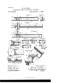
- FIG. 1 is a side view of a portion of a metallic railway-tie embodying my improvements.
- Fig. 2 is a top plan view of the same, showing one of the rail-holding clamps in position with reference to the base portion of a rail.
- Fig. 3 is a side view of the same, showing the rail as secured to the tie.
- Fig. l is a transverse section upon the line 0 O of Fig. 1.
- Fig. 5 is a perspective view of the end of the tie with the washer in place thereon.
- FIGS. 6, and 6 are top and side views, respectively, upon an enlarged scale, of one of the railclainps in position for securing the rail.
- Figs. 7,8, 9, 10, and 11 are detailed views of the clamps and washers; and
- Fig. 12 is an enlarged detail in perspective of one of the clamps shown in connection with the rail-base and with its arms or projecting lugs in engagement with the notches provided for their reception in the upper flange of the tie.
- A designates the tie, which is provided with a broad and flattened base portion A, and at points at which the rails are to be secured suitable braces B B are provided to stiffen the web of the tie and transfer the strain to the bed or base portion.
- Theupper face of the tie which forms the bearing for the rail-base, is slightly wider than the thickness of the web of the tie, as is clearly shown in Fig. 2 of the drawings,being designated as O.
- This upper portion 0 presents a perfectly level upper face throughout the entire length of the tie, excepting that at the extreme ends of the tie integral lugs A are provided for a purpose which will be presently explained.
- the top portion 0 is cut away, as shown at E, and at points adjacent to the ends of the tie this top portion 0 is provided with notches c 0, there being preferably several of these notches in each set, as shown.
- the washers and clamping devices which I employ in securing the rail to the tie are constructed of metal and are each provided with a central opening corresponding in size and form with the cross-section of the upper portion 0 of the tie, and each of the said securing devices is also provided upon its under side with an opening I) of a width which will permit of its being readily passed over the web of the tie at the central point E, where the top portion of the tie is cut away.
- the washer D which may be of any thickness required, is first placed over the web at the opening E at the center of the tie, and the said washer is then moved along the tie until it is brought into engagement with the lug A
- the railclamp G which at one of its ends is provided with an extension G and at its other end with an extension G having its under face beveled so as to conform to the bevel of the upper face of the rail-base, is then passed over the web of the tie at the opening E and is moved into contact with the washer D, the end of the arm or extension G contacting with the Washer.
- the rail I is then placed upon the face of the tie and is forced laterally against the clamp G until the outer edge of the base portion of the rail is forced beneath the beveled extension G2 of the clamp.
- the clamp F is next placed upon the tie and is forced into contact with the inner edge of the base of the rail, the said clamp F being provided with an extension F which engages the base portion of the rail while the opposite end of said clamp F is furnished with lugs or arms F, which lugs or arms are, when the clamp has been forced into contact with the rail-base, bent inward and thus caused to engage the notches c in the top portion of the tie.
- an assortment of washers of different widths may be provided, so that a washer of such thickness as to afford the proper adjustment may be used.
- a metallic railway tie the weband upper portion of which are together substantially T shaped in cross section, the combination, with the base portion, the Web, and the top portion provided at its ends with lugs, and recessed at a point intermediate of its ends to receive the rail securing devices and provided at points adjacent to its ends with notches c, substantially as shown and described.
- the washer adapted to be moved into engagement with the inner end of said lug, and the clamp C also movable on the tie and having an extension C adapted to pass over the upper face of the lug upon the tie, and havinga beveled extension 0 to engage the beveled base portion of the rail, substantially as shown and described.
- said clamping device being pro ided at one of its ends with an extension l beveled as described to engage the beveled portion of the rail base, and at its opposite end provided with arms or extensions F adapted to be forced into engagement with notches upon the tie and when so engaged to hold the clamp in a locked position relative to the rail base, substantially as shown and described.
- a washer for use upon T shaped railway ties of the character described consisting of a body portion having an opening therein corresponding with the form of the upper portion of the tie in cross section and having one of its sides cut away to adapt it to pass over the web of the tie, substantially as shown and described.
Landscapes
- Engineering & Computer Science (AREA)
- Architecture (AREA)
- Civil Engineering (AREA)
- Structural Engineering (AREA)
- Machines For Laying And Maintaining Railways (AREA)
Description
(N6 Model.) R. G. KING.
METALLIO RAILWAY TIE AND RAIL FASTENING; No. 547,267. Patented Oct. 1, 1895.
RUSSEL G. KING, OF LAFAYETTE, NEW YORK.
METALLIC RAILWAY-TIE AND RAIL-FASTENING.
SPECIFICATION forming part of Letters Patent No. 547,267, dated October 1, 1895.
Application filed August 23, 1895- Serial No. 560,245. (No model.)
T0 at whom it may concern.-
Be it known that I, RUssEL G. KING, acitizen of the United States, residing at Lafayette, in the county of Onondaga and State of New York, have invented certain new and useful Improvements in Metallic Railway-Ties and Rail-Fastenings; and I do declare the following to be a full, clear, and exact description of the invention, such as will enable others skilled in the art to which it appertains to make and use the same, reference being had to the accompanying drawings, and to the letters of reference marked thereon, which form a part of this specification.
This invention relates to certain new and useful improvements in metallic railway-ties and rail-fastenings; and it has for its objects, among others, the provision of a simple, strong, and durable metallic tie and in providing in connection therewith a simple and efficient means whereby the railway-rail may be quickly and easilysecured to the tie without necessitating the use of bolts, screws, or, in fact, of any of the various devices which are commonly used for this purpose.
The invention has for a further object the provision of means whereby the rail may be readily adjusted to the required gage width.
A further and essential object of the invention consists in the provision of a metallic tie having a uniform and level upper face devoid entirely of projections or depressions, thereby rendering the tie suitable for use in connection with switches, as the movable switch-rails when resting upon a series of ties placed in close proximity may be freely moved laterally, the only change required in the form of the ties when the same are designed for use in connection with switches consisting in simply lengthening the tie, as when used in this connection longer ties are required than upon the roadway proper.
To these ends and to such others as the invention may pertain the same consists in the accompanying drawings, which, with the let ters of reference marked thereon, form a part of this specification, and in which drawings Figure 1 is a side view of a portion of a metallic railway-tie embodying my improvements. Fig. 2 is a top plan view of the same, showing one of the rail-holding clamps in position with reference to the base portion of a rail. Fig. 3 is a side view of the same, showing the rail as secured to the tie. Fig. l is a transverse section upon the line 0 O of Fig. 1. Fig. 5 is a perspective view of the end of the tie with the washer in place thereon. Figs. 6 and 6 are top and side views, respectively, upon an enlarged scale, of one of the railclainps in position for securing the rail. Figs. 7,8, 9, 10, and 11 are detailed views of the clamps and washers; and Fig. 12 is an enlarged detail in perspective of one of the clamps shown in connection with the rail-base and with its arms or projecting lugs in engagement with the notches provided for their reception in the upper flange of the tie.
Reference now being had to the details of the drawings by letter, A designates the tie, which is provided with a broad and flattened base portion A, and at points at which the rails are to be secured suitable braces B B are provided to stiffen the web of the tie and transfer the strain to the bed or base portion.
Theupper face of the tie, which forms the bearing for the rail-base, is slightly wider than the thickness of the web of the tie, as is clearly shown in Fig. 2 of the drawings,being designated as O. This upper portion 0 presents a perfectly level upper face throughout the entire length of the tie, excepting that at the extreme ends of the tie integral lugs A are provided for a purpose which will be presently explained.
At the longitudinal center of the tie the top portion 0 is cut away, as shown at E, and at points adjacent to the ends of the tie this top portion 0 is provided with notches c 0, there being preferably several of these notches in each set, as shown.
The washers and clamping devices which I employ in securing the rail to the tie, and which devices are shown in detail in Figs. 7 to 11, inclusive, of the drawings, are constructed of metal and are each provided with a central opening corresponding in size and form with the cross-section of the upper portion 0 of the tie, and each of the said securing devices is also provided upon its under side with an opening I) of a width which will permit of its being readily passed over the web of the tie at the central point E, where the top portion of the tie is cut away.
In securing the rail to the tie the washer D, which may be of any thickness required, is first placed over the web at the opening E at the center of the tie, and the said washer is then moved along the tie until it is brought into engagement with the lug A The railclamp G, which at one of its ends is provided with an extension G and at its other end with an extension G having its under face beveled so as to conform to the bevel of the upper face of the rail-base, is then passed over the web of the tie at the opening E and is moved into contact with the washer D, the end of the arm or extension G contacting with the Washer. The rail I is then placed upon the face of the tie and is forced laterally against the clamp G until the outer edge of the base portion of the rail is forced beneath the beveled extension G2 of the clamp. The clamp F is next placed upon the tie and is forced into contact with the inner edge of the base of the rail, the said clamp F being provided with an extension F which engages the base portion of the rail while the opposite end of said clamp F is furnished with lugs or arms F, which lugs or arms are, when the clamp has been forced into contact with the rail-base, bent inward and thus caused to engage the notches c in the top portion of the tie.
It will be seen that by the construction above described the use of bolts is entirely avoided and that the rails will at all times be held securely against the possibility of accidental displacement by the engagement of the lugs F with the notches c.
In order to provide for possible variations in the width of the bases of rails, an assortment of washers of different widths may be provided, so that a washer of such thickness as to afford the proper adjustment may be used.
That I claim to be new, and desire to secure by Letters Patent, is
1. In a metallic railway tie the weband upper portion of which are together substantially T shaped in cross section, the combination, with the base portion, the Web, and the top portion provided at its ends with lugs, and recessed at a point intermediate of its ends to receive the rail securing devices and provided at points adjacent to its ends with notches c, substantially as shown and described.
2. In combination with a metallic railway tie T shaped in cross section and provided with notches as described, of rail clamps adapted to move longitudinally upon the upper portion of the tie, and lugs or projections extending rearwardly from the side walls of the clamp adapted when forced into engagement with the notches upon the tie to hold the clamp into engagement with the base portion of the rail, substantially as shown, and described. v
3. In combination with a metallic railway tie of a rail clamping device longitudinally movable thereon and provided with lugs or projections extending rearwardly from the side walls of the clamp adapted to be forced into engagement with notches or shoulders upon the tie, and when thus engaged to hold the clamp in a locked position relative to the rail base, substantially as shown and described.
at. In combination with a railway tie substantially T shaped in cross section and provided at its ends with lugs as described, the washer adapted to be moved into engagement with the inner end of said lug, and the clamp C also movable on the tie and having an extension C adapted to pass over the upper face of the lug upon the tie, and havinga beveled extension 0 to engage the beveled base portion of the rail, substantially as shown and described.
5. In combination with the upper portion of a metallic railway tie of the rail clamping device F movable thereon said clamping device, being pro ided at one of its ends with an extension l beveled as described to engage the beveled portion of the rail base, and at its opposite end provided with arms or extensions F adapted to be forced into engagement with notches upon the tie and when so engaged to hold the clamp in a locked position relative to the rail base, substantially as shown and described.
6. A washer for use upon T shaped railway ties of the character described, the same consisting of a body portion having an opening therein corresponding with the form of the upper portion of the tie in cross section and having one of its sides cut away to adapt it to pass over the web of the tie, substantially as shown and described.
.In testimony whereof I affix my signature in presence of two Witnesses.
- RUSSEL G. KING. Witnesses:
I. N. AMES, EUNICE WI-IITMORE.
Publications (1)
| Publication Number | Publication Date |
|---|---|
| US547267A true US547267A (en) | 1895-10-01 |
Family
ID=2616010
Family Applications (1)
| Application Number | Title | Priority Date | Filing Date |
|---|---|---|---|
| US547267D Expired - Lifetime US547267A (en) | Ietallic railway-tie and rail-fastening |
Country Status (1)
| Country | Link |
|---|---|
| US (1) | US547267A (en) |
-
0
- US US547267D patent/US547267A/en not_active Expired - Lifetime
Similar Documents
| Publication | Publication Date | Title |
|---|---|---|
| US626233A (en) | Metallic railway tie | |
| US803864A (en) | Metal railway-tie. | |
| US21007A (en) | Improvement in compound rails for railroads | |
| US697480A (en) | Railway-tie. | |
| US885377A (en) | Metal railway-tie. | |
| US779269A (en) | Metallic tie. | |
| US1218425A (en) | Rail-brace. | |
| US1392398A (en) | William a | |
| US1124773A (en) | Rail-fastening means. | |
| US1067127A (en) | Rail-tie and rail-fastening. | |
| US1392562A (en) | Railway-tie and rail-fastener | |
| US365350A (en) | Railroad-rail tie and fastening | |
| US631618A (en) | Railway-tie. | |
| US1055956A (en) | Railway-rail fastener. | |
| US1482676A (en) | Antispreading device | |
| US728026A (en) | Metallic railway-tie. | |
| US842752A (en) | Railway-tie. | |
| US514243A (en) | Rail-chair | |
| US1048606A (en) | Rail-joint. | |
| US1779326A (en) | Metallic tie | |
| US849946A (en) | Means for preventing rails from spreading. | |
| US1148852A (en) | Rail-fastening device. | |
| US994589A (en) | Metallic tie and rail-fastener. | |
| US813611A (en) | Metallic railway-tie. | |
| US1108776A (en) | Rail-fastener. |