US5454401A - Method of lining a branch pipe - Google Patents
Method of lining a branch pipe Download PDFInfo
- Publication number
- US5454401A US5454401A US08/275,106 US27510694A US5454401A US 5454401 A US5454401 A US 5454401A US 27510694 A US27510694 A US 27510694A US 5454401 A US5454401 A US 5454401A
- Authority
- US
- United States
- Prior art keywords
- branch pipe
- liner bag
- bag
- pipe liner
- fluid pressure
- Prior art date
- Legal status (The legal status is an assumption and is not a legal conclusion. Google has not performed a legal analysis and makes no representation as to the accuracy of the status listed.)
- Expired - Fee Related
Links
Images


Classifications
-
- B—PERFORMING OPERATIONS; TRANSPORTING
- B29—WORKING OF PLASTICS; WORKING OF SUBSTANCES IN A PLASTIC STATE IN GENERAL
- B29C—SHAPING OR JOINING OF PLASTICS; SHAPING OF MATERIAL IN A PLASTIC STATE, NOT OTHERWISE PROVIDED FOR; AFTER-TREATMENT OF THE SHAPED PRODUCTS, e.g. REPAIRING
- B29C63/00—Lining or sheathing, i.e. applying preformed layers or sheathings of plastics; Apparatus therefor
- B29C63/26—Lining or sheathing of internal surfaces
- B29C63/34—Lining or sheathing of internal surfaces using tubular layers or sheathings
- B29C63/36—Lining or sheathing of internal surfaces using tubular layers or sheathings being turned inside out
-
- B—PERFORMING OPERATIONS; TRANSPORTING
- B29—WORKING OF PLASTICS; WORKING OF SUBSTANCES IN A PLASTIC STATE IN GENERAL
- B29C—SHAPING OR JOINING OF PLASTICS; SHAPING OF MATERIAL IN A PLASTIC STATE, NOT OTHERWISE PROVIDED FOR; AFTER-TREATMENT OF THE SHAPED PRODUCTS, e.g. REPAIRING
- B29C63/00—Lining or sheathing, i.e. applying preformed layers or sheathings of plastics; Apparatus therefor
- B29C63/26—Lining or sheathing of internal surfaces
- B29C63/34—Lining or sheathing of internal surfaces using tubular layers or sheathings
- B29C63/346—Fixing the end of the lining
-
- F—MECHANICAL ENGINEERING; LIGHTING; HEATING; WEAPONS; BLASTING
- F16—ENGINEERING ELEMENTS AND UNITS; GENERAL MEASURES FOR PRODUCING AND MAINTAINING EFFECTIVE FUNCTIONING OF MACHINES OR INSTALLATIONS; THERMAL INSULATION IN GENERAL
- F16L—PIPES; JOINTS OR FITTINGS FOR PIPES; SUPPORTS FOR PIPES, CABLES OR PROTECTIVE TUBING; MEANS FOR THERMAL INSULATION IN GENERAL
- F16L55/00—Devices or appurtenances for use in, or in connection with, pipes or pipe systems
- F16L55/16—Devices for covering leaks in pipes or hoses, e.g. hose-menders
- F16L55/162—Devices for covering leaks in pipes or hoses, e.g. hose-menders from inside the pipe
- F16L55/165—Devices for covering leaks in pipes or hoses, e.g. hose-menders from inside the pipe a pipe or flexible liner being inserted in the damaged section
- F16L55/1651—Devices for covering leaks in pipes or hoses, e.g. hose-menders from inside the pipe a pipe or flexible liner being inserted in the damaged section the flexible liner being everted
-
- F—MECHANICAL ENGINEERING; LIGHTING; HEATING; WEAPONS; BLASTING
- F16—ENGINEERING ELEMENTS AND UNITS; GENERAL MEASURES FOR PRODUCING AND MAINTAINING EFFECTIVE FUNCTIONING OF MACHINES OR INSTALLATIONS; THERMAL INSULATION IN GENERAL
- F16L—PIPES; JOINTS OR FITTINGS FOR PIPES; SUPPORTS FOR PIPES, CABLES OR PROTECTIVE TUBING; MEANS FOR THERMAL INSULATION IN GENERAL
- F16L55/00—Devices or appurtenances for use in, or in connection with, pipes or pipe systems
- F16L55/16—Devices for covering leaks in pipes or hoses, e.g. hose-menders
- F16L55/179—Devices for covering leaks in pipes or hoses, e.g. hose-menders specially adapted for bends, branch units, branching pipes or the like
-
- F—MECHANICAL ENGINEERING; LIGHTING; HEATING; WEAPONS; BLASTING
- F16—ENGINEERING ELEMENTS AND UNITS; GENERAL MEASURES FOR PRODUCING AND MAINTAINING EFFECTIVE FUNCTIONING OF MACHINES OR INSTALLATIONS; THERMAL INSULATION IN GENERAL
- F16L—PIPES; JOINTS OR FITTINGS FOR PIPES; SUPPORTS FOR PIPES, CABLES OR PROTECTIVE TUBING; MEANS FOR THERMAL INSULATION IN GENERAL
- F16L58/00—Protection of pipes or pipe fittings against corrosion or incrustation
- F16L58/02—Protection of pipes or pipe fittings against corrosion or incrustation by means of internal or external coatings
Definitions
- the present invention relates to lining techniques, and more particularly to a method of lining inner walls of aged or defective branch pipes.
- the pipe repair method comprises inserting a sufficiently long tubular flexible liner bag into the pipe to be repaired by means of a pressurized fluid, like air and water.
- the tubular liner bag is made of a flexible resin-absorbent material impregnated with a thermosetting resin, and has the outer surface covered with an impermeable plastic film.
- the tubular flexible liner bag is closed at one end and open at the other; the tubular flexible liner bag is first flattened, then, the closed end of the tubular liner bag is tied to a control rope; the open end of the tubular liner bag is made to gape wide and hooked (anchored) at the end of the defective or old pipe in a manner such that the wide-opened end of the liner completely and fixedly covers and closes the pipe end; a portion of the liner is pushed into the pipe; then, the pressurized fluid is applied to the portion of the tubular liner such that the fluid presses the tubular liner to enter the pipe.
- the everted tubular liner is pressed against the inner wall of the pipe by the pressurized fluid, and the tubular flexible liner is hardened as the thermosetting resin impregnated in the liner is heated, which is effected by heating the fluid filling the tubular lines bag by means of a hot steam, etc. It is thus possible to line the inside wall of the defective or old pipe with a rigid liner without digging the ground and disassembling the pipe sections.
- the above-mentioned method may also be applied to the lining of a branch pipe which is branched from a main pipe, an example of which is illustrated in FIG. 10.
- FIG. 10 is a cross-sectional view showing a conventional method of lining a branch pipe.
- a pressure bag 112 for everting a branch pipe liner bag 104 is inserted into a main pipe 101.
- a branch pipe 102 to be repaired is branched from the main pipe 101 as illustrated. Since this pressure bag 112 must be separated from the branch pipe liner bag 104, a sealing tube 140 should be connected to the pressure bag 112 in order to apply a pressure to the branch pipe liner bag 104.
- the pressure bag 112 is supplied with compressed air to evert both the sealing tube 140 and the branch pipe liner bag 104 into the branch pipe 102.
- the branch pipe liner bag 104 is, for example, heated to harden a hardenable resin impregnated therein.
- the sealing tube 140 is pulled out from the branch pipe 102 (branch pipe liner bag 104)
- the branch pipe 102 is reinforced by the hardened branch pipe liner bag 104 which has been lined on the inner wall of the branch pipe 102.
- the above-mentioned method must prepare the sealing tube 140 of an appropriate length in accordance with variations in length of the branch pipe 102 each time it is to be repaired. Therefore, the sealing tube 140 must be exchanged for each branch pipe according to its length.
- FIGS. 11 and 12 are cross-sectional views used for explaining a conventional branch pipe lining method which does not need a sealing tube as that indicated by 140 in FIG. 10.
- This method utilizes a separator tube 240 to realize an air-tight connection between a pressure bag 212 for eversion and a branch pipe liner bag 204.
- One end of the separator tube 240 is temporarily connected to the branch pipe liner bag 204.
- reference numeral 241 designates a guide tube; 242 an air mat for pressing a flange 204a of the branch pipe liner bag 204 against the inner wall of a main pipe 201; and 203 a robot introduced into the main pipe 201 for the lining operations.
- the pressure bag 212 is moved in the direction indicated by arrows. Since the pressure bag 212 is coupled with the robot 203 through the guide tube 241, the robot 203 is also moved in the same direction. Further, the separator tube 240 temporarily connected to the branch pipe liner bag 204 is torn off from the temporarily connected area so that it is separated from the branch pipe liner bag 204.
- this conventional method utilizes the separator tube 240 to realize an air-tight connection between the pressure bag 212 and the branch pipe liner bag 204, the same separator tube 240 can be used irrespective of the length of a branch pipe to be repaired, so that the exchange of the sealing tube 140, which would be required by the method shown in FIG. 10, is made unnecessary.
- the proposed method however has a drawback that the separator tube 240 may not be completely torn off so that part thereof remains on the inner wall of the branch pipe liner bag, wherein the remaining part acts as burr to cause an unfavorable condition of the inner wall. Specifically, flowing substances within the branch pipe may attach to the burr.
- the present invention has been made in view of the above-mentioned problem, and it is an object of the present invention to provide a branch pipe lining method which is capable of maintaining the inner wall of a branch pipe in a favorable condition after repair operations.
- the present invention provides a method of lining a branch pipe using a branch pipe liner bag impregnated with a hardenable resin and having a flange at one end thereof, comprising the steps of: folding out the flange to mount the same to a fluid pressure sealing nozzle; everting the branch pipe liner bag and inserting the same from a main pipe into a branch pipe toward the ground, pulling up an upper end of the branch pipe liner bag with the flange thereof secured on the inner wall of the main pipe; removing the fluid pressure sealing nozzle from the branch pipe liner bag; expanding a sealing pressure bag introduced into the main pipe to seal a lower opening of the branch pipe liner bag with the sealing pressure bag; closing the upper end of the branch pipe liner bag, and pressing the branch pipe liner bag against the inner wall of the branch pipe with a fluid pressure; and hardening the hardenable resin impregnated in the branch pipe liner bag while the branch pipe liner bag is continuously being pressed against the inner wall of the branch pipe.
- an air-tight connection between the pressure bag for eversion and the branch pipe liner bag is acheved without using a conventional separator tube, and the lower opening of the branch pipe liner bag is sealed by the sealing pressure bag during hardening the branch pipe liner bag, so that any defective residue remains on the inner wall of the branch pipe and accordingly its surface is maintained in a favorable condition.
- FIGS. 1-3 are cross-sectional views showing a branch pipe lining method according to the present invention in the order of its processes
- FIGS. 4(a)-4(d) show exemplary sealing structures for realizing an air-tight connection between a fluid pressure sealing nozzle and a branch pipe liner bag;
- FIG. 5 is a cross-sectional view showing another embodiment of a structure for sealing an upper end of a branch pipe liner bag
- FIG. 6 is a cross-sectional view showing a sealing pressure bag which is arranged behind a pressure bag for eversion;
- FIG. 7 is a cross-sectional view showing another embodiment for simultaneously sealing lower openings of a plurality of branch pipe liner bags
- FIGS. 8 and 9 show other embodiments of the present invention in cross-sectional form.
- FIGS. 10-12 are cross-sectional views showing a conventional branch pipe lining method.
- FIGS. 1-3 are cross-sectional views showing one embodiment of a method according to the present invention in the order of lining a branch pipe.
- a main pipe 1 has a branch pipe 2 having a smaller diameter and branched therefrom.
- a robot 3, a branch pipe liner bag 4 and so on are arranged in the main pipe 1, while a TV camera 5 for monitoring the inside of the branch pipe 21 is suspended from the above to be placed in the branch pipe 2, as illustrated.
- the robot 3 is a hydraulically driven type and has a head 6 arranged for bi-directional movements along an arrow a as well as for rotation in the direction indicated by an arrow b.
- the head 6 also supports a fluid pressure sealing nozzle 7.
- the robot 3 is tied with pull ropes 8, 9 and further is equipped on the top surface thereof with a TV camera 10 for monitoring the inside of the main pipe and a lamp 11 for illumination.
- the branch pipe liner bag 4 is mounted to the fluid pressure sealing nozzle 7, the branch pipe liner bag 4 is mounted. More specifically, the branch pipe liner bag 11 is formed of a tubular unwoven fabric member impregnated with an unhardened thermosetting resin and having the outer surface covered with a highly sealable plastic film. One end of the branch pipe liner bag 4 is folded back to form a flange 4a, as illustrated, which is sandwiched between the nozzle 7 and the inner wall of the main pipe 1.
- the thermosetting resin impregnated in the flange 4a has previously been hardened such that the flange 4a can maintain its predetermined shape (i.e., flange 4a has an arcuate surface in conformity to the shape of the inner wall of the main pipe 1).
- the plastic film covering the tubular unwoven fabric member may comprise a film made of polyethylene, vinyl chloride vinylon polyurethane, nylon, polypropylene, polyethylene/nylon co-polymer or the like. Materials suitable to the tubular unwoven fabric member may include polyester, nylon, acrylic resin, and vinylon. Also, the thermosetting resin may be unsaturated polyester, epoxy resin or the like.
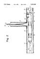
- the branch pipe liner bag 4 with its flange 4a mounted to the fluid pressure sealing nozzle 7 has the remaining uneverted portion extending through the nozzle 7 into a pressure bag 12 for everting the branch pipe liner bag 4, as shown in FIG. 1.
- the pressure bag 12 has one end thereof mounted to the fluid pressure sealing nozzle 7 and the other end closed by a cap 13.
- the pressure bag 12 is also connected to a compressor 15 through an air hose 14.
- the pressure bag 12 is further provided over the outer surface thereof with an expandable and contractible tubular sealing pressure bag 16 which is connected to a compressor 18 through an air hose 17.
- the cap 13 is tied to one end of a pull rope 19.
- Pulling the pull ropes 8, 9 causes the robot 3 as well as the branch pipe liner bag 4, the pressure bag 12 and so on supported by the robot 3 to integrally move in the main pipe 1.
- the flange 4a of the branch pipe liner bag 4 is positioned at an opening communicating with the branch pipe 2, as shown in FIG. 1.
- the head 6 of the robot 3 is moved upward to press the flange 4a of the branch pipe liner bag 4 against the inner wall of the main pipe 1 such that the flange 4a is closely contacted to the inner wall of the main pipe 1.
- the compressor 15 is next driven to supply compressed air to the pressure bag 12, 216 through the air hose 14, so that the branch pipe liner bag 4 is rolled inside out by the pressure of the compressed air and is successively inserted from the main pipe 1 into the branch pipe 2 toward the ground (upward direction).
- FIG. 4(a) shows a sealing structure employed in this embodiment, wherein the fluid pressure sealing nozzle 207 is formed with a tapered protrusion 207a which is used to maintain an air-tight connection between the fluid pressure sealing nozzle 207 and the branch pipe liner bag 204.
- FIG. 4(b) shows a sealing structure for maintaining an air-tight connection between the fluid pressure sealing nozzle 207 and the branch pipe liner bag 204 by means of an O-ring 230 provided in the fluid pressure sealing nozzle 207
- FIG. 4(c) shows another sealing structure for the same purpose by means of a valve 231 provided on the fluid pressure sealing nozzle 207.
- FIG. 4(d) shows a sealing structure for maintaining an air-tight connection between the fluid pressure sealing nozzle 207 and the branch pipe liner bag 4 by means of a magnetic plate 232 embedded in the flange 204a of the branch pipe liner bag 204 and a magnet 233 arranged on the nozzle 207 at a location opposing to the magnetic plate 232 such that the magnetic plate 232 and the magnet 233 attract to each other.
- a cap 25 is mounted on the upper end of the branch pipe liner bag 4, as shown in FIG. 3, through which compressed air is supplied to the branch pipe liner bag 4 through an air hose 27 by driving a compressor 26.
- This causes the branch pipe liner bag 4 to be expanded by the pressure of the compressed air and accordingly pressed against the inner wall of the branch pipe 2.
- the cap 25 may be equipped with a pressure gauge 28 and a safety valve 29, as illustrated.
- thermosetting resin impregnated in the branch pipe liner bag 4 is heated and therefore hardened, whereby the inner wall of the branch pipe 2 is lined by the hardened branch pipe liner bag 4, thus repairing the branch pipe 2.
- the upper end of the branch pipe liner bag 4 may be closed without using the cap 25, and the hot water supply hose 30, the hot water discharge hose 31 and the pressure gauge 28 may be directly inserted into the branch pipe liner bag 4, as shown in FIG. 5.
- an air-tight connection between the pressure bag 12 and the branch pipe liner bag 4 is achieved without a conventional separator tube such as that indicated by 240 in FIG. 11.
- the sealing pressure bag 16 is used to Seal the lower opening of the branch pipe liner bag 4, which is required when the branch pipe liner bag 4 is to be hardened. Since the sealing pressure bag 16 can be easily removed from the branch pipe liner bag 4 after it has been hardened, any fragment of the sealing pressure bag 16 will not remain on the inner wall of the branch pipe 2 (or the branch pipe liner bag 4 lined thereon), after the branch pipe 2 has been lined, so that the inner wall surface of the branch pipe 2 is maintained in a favorable condition.
- the sealing pressure 16 is arranged outside the pressure bag 12 for eversion
- the sealing pressure bag 16 may be placed behind the pressure bag 12 for eversion as shown in FIG. 6.
- a TV camera 32 is connected to the sealing pressure bag 16 on the rear side thereof, as illustrated.
- FIGS. 8 and 9 show another embodiment wherein a filler injecting tube 33 is fixed on the inner wall of a branch pipe liner bag 4 before everted by means of a plurality of tubular fixtures 34. When the branch pipe liner bag 4 is everted, the filler injecting tube 33 appears outside of the branch pipe liner bag 4.
- a pump 35 is driven to fill a gap between the branch pipe 2 and the branch pipe liner bag 4 and the juncture of the main pipe 1 and the branch pipe 2 with a filler 37 such as cement milk, thermosetting resin or the like contained in a tank 36 is supplied through the filler injecting tube 33, with the lower opening of the branch pipe liner bag 4 being still sealed by the sealing pressure bag 16.
- the filler injecting tube 33 may be made of plastic, polyurethane, nylon, vinyl chloride or the like, while the fixtures 34 may be made of tubular plstic fabric, unwoven fabric or film.
- the branch pipe lining method of the present invention utilizes a branch pipe liner bag impregnated with a hardenable resin and having a flange at one end thereof, wherein the flange is folded out and mounted to a fluid pressure sealing nozzle; the branch pipe liner bag is everted and inserted from a main pipe into a branch pipe toward the ground, an upper end of the branch pipe liner bag is pulled up by a rope or the like with the flange thereof secured on the inner wall of the main pipe; the fluid pressure sealing nozzle is removed from the branch pipe liner bag; a sealing pressure bag introduced into the main pipe is expanded to seal a lower opening of the branch pipe liner bag with the sealing pressure bag; the upper end of the branch pipe liner bag is closed, and the branch pipe liner bag is pressed against the inner wall of the branch pipe with a fluid pressure; and the hardenable resin impregnated in the branch pipe liner bag is hardened while the branch pipe liner bag is continuously being pressed against the inner wall of the branch
- sealing pressure bag can be easily removed from the branch pipe liner bag after it has been hardened, any fragment of the sealing pressure bag will not remain on the inner wall of the branch pipe (or the branch pipe liner bag lined thereon), after the branch pipe has been lined, so that the inner wall surface of the branch pipe can be maintained in a favorable condition.
Applications Claiming Priority (2)
| Application Number | Priority Date | Filing Date | Title |
|---|---|---|---|
| JP5-216322 | 1993-08-31 | ||
| JP5216322A JP2528429B2 (ja) | 1993-08-31 | 1993-08-31 | 枝管ライニング工法 |
Publications (1)
| Publication Number | Publication Date |
|---|---|
| US5454401A true US5454401A (en) | 1995-10-03 |
Family
ID=16686717
Family Applications (1)
| Application Number | Title | Priority Date | Filing Date |
|---|---|---|---|
| US08/275,106 Expired - Fee Related US5454401A (en) | 1993-08-31 | 1994-07-14 | Method of lining a branch pipe |
Country Status (7)
| Country | Link |
|---|---|
| US (1) | US5454401A (ja) |
| EP (1) | EP0640787B1 (ja) |
| JP (1) | JP2528429B2 (ja) |
| KR (1) | KR0178144B1 (ja) |
| DE (1) | DE69414496T2 (ja) |
| DK (1) | DK0640787T3 (ja) |
| MY (1) | MY111281A (ja) |
Cited By (39)
| Publication number | Priority date | Publication date | Assignee | Title |
|---|---|---|---|---|
| US5597353A (en) * | 1994-10-07 | 1997-01-28 | Insituform (Netherlands) B.V. | Compact apparatus for everting a liner and method |
| US5624629A (en) * | 1990-04-23 | 1997-04-29 | Insituform (Netherlands) B.V. | Installation of lateral linings with sealing collar from the main pipeline out |
| WO1997035707A1 (en) * | 1996-03-25 | 1997-10-02 | Ina Acquisition Corp. | Method for lining of lateral pipelines with flow-through apparatus |
| US5700110A (en) * | 1995-07-07 | 1997-12-23 | Shonan Gosei-Jushi Seisakusho K.K. | Method for lining a bent pipe |
| US5927341A (en) * | 1993-09-25 | 1999-07-27 | Insituform (Netherlands) B.V. | Lining of "Tees" and "Wyes" in pipelines or passageways |
| US5944058A (en) * | 1997-02-04 | 1999-08-31 | Shonan Gosei-Jushi Seisakusho K.K. | Branch pipe liner assembly and a pipe lining method |
| US5950682A (en) * | 1994-08-19 | 1999-09-14 | Lmk Enterprises, Inc. | Apparatus and method for repairing the junction of a sewer main line and lateral |
| US5971031A (en) * | 1997-10-06 | 1999-10-26 | Shona Gosei-Jushi Seiksakusho K.K. | Branch pipe liner bag and pipe lining method |
| US6006787A (en) * | 1998-02-12 | 1999-12-28 | Shonan Gosei-Jushi Seisakusho K.K. | Branch pipe liner bag and branch pipe lining method |
| US6039079A (en) * | 1998-07-17 | 2000-03-21 | Lmk Enterprises, Inc. | Apparatus and method for repairing the junction of a sewer main line and lateral pipe |
| US6056017A (en) * | 1998-01-27 | 2000-05-02 | Shonan Gosei-Jushi Seisakusho K.K. | Pipe lining method |
| US6085794A (en) * | 1998-10-26 | 2000-07-11 | Shonan Gosei-Jushi Seisakusho K.K. | Pipe lining method |
| US6123109A (en) * | 1997-02-04 | 2000-09-26 | Shonan Gosei-Jushi Seisakusho K.K. | Branch pipe lining bag and pipe lining method |
| US6152184A (en) * | 1998-02-27 | 2000-11-28 | Shonan Gosei-Jushi Seisakusho K.K. | Branch pipe liner bag and branch pipe lining method |
| US6158473A (en) * | 1998-08-06 | 2000-12-12 | Shonan Gosei-Jushi Seisakusho K.K. | Branch pipe liner bag and pipe lining method |
| US6337114B1 (en) | 1992-09-10 | 2002-01-08 | Insituform (Netherlands) B.V. | Flexible lining with flexible collar for lining lateral pipelines |
| US20020052591A1 (en) * | 2000-10-27 | 2002-05-02 | Zehner Georgia Lynn | Absorbent article with captured leg elastics |
| US6484757B1 (en) | 2002-03-19 | 2002-11-26 | Liqui-Force Sewer Services Inc. | Method and device for lining a lateral sewer pipe |
| US20030116211A1 (en) * | 2001-12-19 | 2003-06-26 | Ward Robert M. | Apparatus and method for the robotic repairing of an underground pipe junction with a flexible patch mechanism |
| US20040020544A1 (en) * | 2002-04-05 | 2004-02-05 | Takao Kamiyama | Pressure bag and method of lining branch pipe |
| US6701966B1 (en) * | 2003-04-22 | 2004-03-09 | Infrastructure Repair Systems, Inc. | Apparatus for lateral line repair |
| US20040045617A1 (en) * | 2000-05-18 | 2004-03-11 | Takao Kamiyama | Pipe liner bag everting nozzle and pipe lining method |
| US20040161301A1 (en) * | 2003-02-14 | 2004-08-19 | Olaleke Osibamowo | Sealing the junction region where a lateral pipe and a main pipe meet |
| US20050133105A1 (en) * | 2003-11-12 | 2005-06-23 | In.Tec S.R.L. | Device and a process for non-destructive repair of a side inlet pipe of a main sewer of a draining pipe |
| US20060130922A1 (en) * | 2004-10-27 | 2006-06-22 | Shonan Gosei-Jushi Seisakusho K.K. | Lateral pipe lining material and lateral pipe lining method |
| US20080169036A1 (en) * | 2007-01-12 | 2008-07-17 | Takao Kamiyama | Lateral pipe lining material and lateral pipe lining method using same |
| US20080236692A1 (en) * | 2007-03-30 | 2008-10-02 | Lmk Enterprises, Inc. | Bladderless pipeliner and method for using same |
| US20080245433A1 (en) * | 2007-04-03 | 2008-10-09 | Darcy Warren | Lateral liner with seal |
| US20100139799A1 (en) * | 2008-12-04 | 2010-06-10 | Shonan Gosei-Jushi Seisakusho K.K. | Method for rehabilitating existing pipes, and rehabilitation pipe segment used in said method |
| US20100276202A1 (en) * | 2007-11-21 | 2010-11-04 | Petrus Cornelis Kriesels | Method of drilling a wellbore |
| US20100331959A1 (en) * | 2007-10-29 | 2010-12-30 | Petrus Cornelis Kriesels | Method of radially expanding a tubular element |
| US20120060346A1 (en) * | 2010-09-10 | 2012-03-15 | Shonan Gosei-Jushi Seisakusho K.K. | Lateral pipe lining method and lateral pipe lining apparatus |
| US20130233428A1 (en) * | 2008-02-01 | 2013-09-12 | Wpw, Llc | Systems and methods for locating and restoring service lines in pipeline rehabilitation |
| US20140048151A1 (en) * | 2011-05-06 | 2014-02-20 | Andreas Bichler | Calibration hose |
| US20150328857A1 (en) * | 2012-12-07 | 2015-11-19 | Ashimori Industry Co., Ltd. | Lining material for conduit and lining method for conduit |
| US9933105B1 (en) | 2017-04-12 | 2018-04-03 | InnerCure Technologies, LLC | Underground pipe repair device with radial stepped annular spacer and related systems and methods |
| US10309575B2 (en) | 2017-04-12 | 2019-06-04 | Inner Cure Technologies | Underground pipe repair device with radial annular spacers and related systems and methods |
| US10514125B1 (en) | 2017-04-12 | 2019-12-24 | InnerCure Technologies, LLC | Underground pipe repair device with retention device and related systems and methods |
| US11326732B2 (en) | 2017-04-12 | 2022-05-10 | improved Infrastructure Solutions, LLC | Underground pipe repair device with detectable annular body and related systems and methods |
Families Citing this family (5)
| Publication number | Priority date | Publication date | Assignee | Title |
|---|---|---|---|---|
| AUPO695497A0 (en) * | 1997-05-26 | 1997-06-12 | Barry, Kevin Francis | End of line pipeliner |
| AUPP065297A0 (en) * | 1997-12-02 | 1998-01-08 | Harrington, David Richard | System for formed-in-situ localised repair of pipes and conduits |
| DE102010030074A1 (de) | 2010-06-15 | 2011-12-15 | Evonik Degussa Gmbh | Kunststoff-Photovoltaik-Modul und Verfahren zu seiner Herstellung |
| KR102076780B1 (ko) * | 2019-04-22 | 2020-02-12 | 최장환 | 가지관에서의 공기가압을 통한 가지관 보수방법 및 보수장치 |
| DE102020125355A1 (de) * | 2020-09-29 | 2022-03-31 | Brandenburger Liner Gmbh & Co. Kg | Vorrichtung zum radialen aufweiten der endabschnitte eines auskleidungsschlauchs zum auskleiden von defekten rohrleitungen sowie auskleidungsschlauch und verfahren zum einbringen eines solchen in eine defekte rohrleitung |
Citations (4)
| Publication number | Priority date | Publication date | Assignee | Title |
|---|---|---|---|---|
| US4368091A (en) * | 1978-12-29 | 1983-01-11 | Tokyo Gas Co. Ltd. | Method for providing the inner surface of a pipe with a flexible tubular lining material through a liquid resin under pressure |
| US4758454A (en) * | 1985-01-21 | 1988-07-19 | Insituform Group Ltd | Lining of passageways |
| US4836715A (en) * | 1987-02-11 | 1989-06-06 | Insituform International N.V. | Passageway lining material |
| US5329063A (en) * | 1991-05-31 | 1994-07-12 | Get, Inc. | Liner assembly for lining branch pipes and a method for manufacturing the liner assembly |
Family Cites Families (3)
| Publication number | Priority date | Publication date | Assignee | Title |
|---|---|---|---|---|
| CY1392A (en) * | 1981-02-18 | 1987-12-18 | Insituform Pipes & Structures | Lining of side connections |
| GB9009073D0 (en) * | 1990-04-23 | 1990-06-20 | Insituform Group Ltd | Improvements relating to the lining of pipelines or passageways |
| DE9105888U1 (ja) * | 1991-05-13 | 1991-10-24 | Linck, Hans-Peter, 4300 Essen, De |
-
1993
- 1993-08-31 JP JP5216322A patent/JP2528429B2/ja not_active Expired - Fee Related
-
1994
- 1994-03-14 KR KR1019940005001A patent/KR0178144B1/ko not_active IP Right Cessation
- 1994-07-14 US US08/275,106 patent/US5454401A/en not_active Expired - Fee Related
- 1994-07-19 DK DK94305283T patent/DK0640787T3/da active
- 1994-07-19 MY MYPI94001876A patent/MY111281A/en unknown
- 1994-07-19 DE DE69414496T patent/DE69414496T2/de not_active Expired - Fee Related
- 1994-07-19 EP EP94305283A patent/EP0640787B1/en not_active Expired - Lifetime
Patent Citations (4)
| Publication number | Priority date | Publication date | Assignee | Title |
|---|---|---|---|---|
| US4368091A (en) * | 1978-12-29 | 1983-01-11 | Tokyo Gas Co. Ltd. | Method for providing the inner surface of a pipe with a flexible tubular lining material through a liquid resin under pressure |
| US4758454A (en) * | 1985-01-21 | 1988-07-19 | Insituform Group Ltd | Lining of passageways |
| US4836715A (en) * | 1987-02-11 | 1989-06-06 | Insituform International N.V. | Passageway lining material |
| US5329063A (en) * | 1991-05-31 | 1994-07-12 | Get, Inc. | Liner assembly for lining branch pipes and a method for manufacturing the liner assembly |
Cited By (62)
| Publication number | Priority date | Publication date | Assignee | Title |
|---|---|---|---|---|
| US20050211372A1 (en) * | 1990-04-23 | 2005-09-29 | Eric Wood | Installation of flexible lining with flexible collar for lining lateral pipelines |
| US5624629A (en) * | 1990-04-23 | 1997-04-29 | Insituform (Netherlands) B.V. | Installation of lateral linings with sealing collar from the main pipeline out |
| US6899832B2 (en) | 1990-04-23 | 2005-05-31 | Insituform (Netherlands) B.V. | Installation of flexible lining with flexible collar for lining lateral pipelines |
| US5975878A (en) * | 1990-04-23 | 1999-11-02 | Insituform (Netherlands) B.V. | Apparatus for installation of lining with sealing collar |
| US20030168161A1 (en) * | 1990-04-23 | 2003-09-11 | Insituform (Netherlands) B.V. | Installation of flexible lining with flexible collar for lining lateral pipelines |
| US6337114B1 (en) | 1992-09-10 | 2002-01-08 | Insituform (Netherlands) B.V. | Flexible lining with flexible collar for lining lateral pipelines |
| US5927341A (en) * | 1993-09-25 | 1999-07-27 | Insituform (Netherlands) B.V. | Lining of "Tees" and "Wyes" in pipelines or passageways |
| US5950682A (en) * | 1994-08-19 | 1999-09-14 | Lmk Enterprises, Inc. | Apparatus and method for repairing the junction of a sewer main line and lateral |
| US5597353A (en) * | 1994-10-07 | 1997-01-28 | Insituform (Netherlands) B.V. | Compact apparatus for everting a liner and method |
| US5942183A (en) * | 1994-10-07 | 1999-08-24 | Insituform (Netherlands) B.V. | Method for everting a liner using a compact apparatus |
| US5700110A (en) * | 1995-07-07 | 1997-12-23 | Shonan Gosei-Jushi Seisakusho K.K. | Method for lining a bent pipe |
| US6001212A (en) * | 1996-03-25 | 1999-12-14 | Insituform (Netherlands) B.V. | Method for lining of lateral pipelines with flow-through apparatus |
| WO1997035707A1 (en) * | 1996-03-25 | 1997-10-02 | Ina Acquisition Corp. | Method for lining of lateral pipelines with flow-through apparatus |
| US6123109A (en) * | 1997-02-04 | 2000-09-26 | Shonan Gosei-Jushi Seisakusho K.K. | Branch pipe lining bag and pipe lining method |
| US5944058A (en) * | 1997-02-04 | 1999-08-31 | Shonan Gosei-Jushi Seisakusho K.K. | Branch pipe liner assembly and a pipe lining method |
| AU733557B2 (en) * | 1997-10-06 | 2001-05-17 | Get Inc. | Branch pipe liner bag and pipe lining method |
| US5971031A (en) * | 1997-10-06 | 1999-10-26 | Shona Gosei-Jushi Seiksakusho K.K. | Branch pipe liner bag and pipe lining method |
| US6056017A (en) * | 1998-01-27 | 2000-05-02 | Shonan Gosei-Jushi Seisakusho K.K. | Pipe lining method |
| US6006787A (en) * | 1998-02-12 | 1999-12-28 | Shonan Gosei-Jushi Seisakusho K.K. | Branch pipe liner bag and branch pipe lining method |
| US6152184A (en) * | 1998-02-27 | 2000-11-28 | Shonan Gosei-Jushi Seisakusho K.K. | Branch pipe liner bag and branch pipe lining method |
| US6039079A (en) * | 1998-07-17 | 2000-03-21 | Lmk Enterprises, Inc. | Apparatus and method for repairing the junction of a sewer main line and lateral pipe |
| US6158473A (en) * | 1998-08-06 | 2000-12-12 | Shonan Gosei-Jushi Seisakusho K.K. | Branch pipe liner bag and pipe lining method |
| US6085794A (en) * | 1998-10-26 | 2000-07-11 | Shonan Gosei-Jushi Seisakusho K.K. | Pipe lining method |
| US7051766B2 (en) * | 2000-05-18 | 2006-05-30 | Takao Kamiyama | Pipe liner bag everting nozzle and pipe lining method |
| US20040045617A1 (en) * | 2000-05-18 | 2004-03-11 | Takao Kamiyama | Pipe liner bag everting nozzle and pipe lining method |
| US20020052591A1 (en) * | 2000-10-27 | 2002-05-02 | Zehner Georgia Lynn | Absorbent article with captured leg elastics |
| US20030116211A1 (en) * | 2001-12-19 | 2003-06-26 | Ward Robert M. | Apparatus and method for the robotic repairing of an underground pipe junction with a flexible patch mechanism |
| US6688337B2 (en) * | 2001-12-19 | 2004-02-10 | Robert M. Ward | Apparatus and method for the robotic repairing of an underground pipe junction with a flexible patch mechanism |
| US6695013B2 (en) | 2002-03-19 | 2004-02-24 | Liqui-Force Sewer Services, Inc. | Method and device for lining a lateral sewer pipe |
| US6484757B1 (en) | 2002-03-19 | 2002-11-26 | Liqui-Force Sewer Services Inc. | Method and device for lining a lateral sewer pipe |
| US20040020544A1 (en) * | 2002-04-05 | 2004-02-05 | Takao Kamiyama | Pressure bag and method of lining branch pipe |
| US20040161301A1 (en) * | 2003-02-14 | 2004-08-19 | Olaleke Osibamowo | Sealing the junction region where a lateral pipe and a main pipe meet |
| US6948883B2 (en) * | 2003-02-14 | 2005-09-27 | Project Building Co. Limited | Sealing the junction region where a lateral pipe and a main pipe meet |
| US6701966B1 (en) * | 2003-04-22 | 2004-03-09 | Infrastructure Repair Systems, Inc. | Apparatus for lateral line repair |
| US20050133105A1 (en) * | 2003-11-12 | 2005-06-23 | In.Tec S.R.L. | Device and a process for non-destructive repair of a side inlet pipe of a main sewer of a draining pipe |
| US20060130922A1 (en) * | 2004-10-27 | 2006-06-22 | Shonan Gosei-Jushi Seisakusho K.K. | Lateral pipe lining material and lateral pipe lining method |
| US7311121B2 (en) | 2004-10-27 | 2007-12-25 | Shonan Gosei-Jushi Seisakusho K.K. | Lateral pipe lining material and lateral pipe lining method |
| US7503349B2 (en) * | 2007-01-12 | 2009-03-17 | Shonan Gosei-Jushi Seisakusho K.K. | Lateral pipe lining material and lateral pipe lining method using same |
| US20080169036A1 (en) * | 2007-01-12 | 2008-07-17 | Takao Kamiyama | Lateral pipe lining material and lateral pipe lining method using same |
| US20080236692A1 (en) * | 2007-03-30 | 2008-10-02 | Lmk Enterprises, Inc. | Bladderless pipeliner and method for using same |
| US7845372B2 (en) | 2007-03-30 | 2010-12-07 | Lmk Enterprises, Inc. | Bladderless pipeliner and method for using same |
| US20080245433A1 (en) * | 2007-04-03 | 2008-10-09 | Darcy Warren | Lateral liner with seal |
| US8316892B2 (en) | 2007-04-03 | 2012-11-27 | Liqui-Force Sewer Services Inc. | Lateral liner with seal |
| US8056642B2 (en) * | 2007-10-29 | 2011-11-15 | Shell Oil Company | Method of radially expanding a tubular element |
| US20100331959A1 (en) * | 2007-10-29 | 2010-12-30 | Petrus Cornelis Kriesels | Method of radially expanding a tubular element |
| US8196669B2 (en) * | 2007-11-21 | 2012-06-12 | Shell Oil Company | Method of drilling a wellbore |
| US20100276202A1 (en) * | 2007-11-21 | 2010-11-04 | Petrus Cornelis Kriesels | Method of drilling a wellbore |
| US9494270B2 (en) * | 2008-02-01 | 2016-11-15 | Wpw, Llc | Systems and methods for locating and restoring service lines in pipeline rehabilitation |
| US20130233428A1 (en) * | 2008-02-01 | 2013-09-12 | Wpw, Llc | Systems and methods for locating and restoring service lines in pipeline rehabilitation |
| US20100139799A1 (en) * | 2008-12-04 | 2010-06-10 | Shonan Gosei-Jushi Seisakusho K.K. | Method for rehabilitating existing pipes, and rehabilitation pipe segment used in said method |
| US8360108B2 (en) * | 2008-12-04 | 2013-01-29 | Shonan Gosei-Jushi Seisakusho K.K. | Method for rehabilitating existing pipes, and rehabilitation pipe segment used in the rehabilitating method |
| US20120060346A1 (en) * | 2010-09-10 | 2012-03-15 | Shonan Gosei-Jushi Seisakusho K.K. | Lateral pipe lining method and lateral pipe lining apparatus |
| US8635753B2 (en) * | 2010-09-10 | 2014-01-28 | Shonan Gosei-Jushi Seisakusho K.K. | Lateral pipe lining method and lateral pipe lining apparatus |
| US20140048151A1 (en) * | 2011-05-06 | 2014-02-20 | Andreas Bichler | Calibration hose |
| US9182065B2 (en) * | 2011-05-06 | 2015-11-10 | Trelleborg Pipe Seals Duisburg Gmbh | Calibration hose |
| US20150328857A1 (en) * | 2012-12-07 | 2015-11-19 | Ashimori Industry Co., Ltd. | Lining material for conduit and lining method for conduit |
| US9962900B2 (en) * | 2012-12-07 | 2018-05-08 | Ashimori Industry Co., Ltd. | Lining material for conduit and lining method for conduit |
| US9933105B1 (en) | 2017-04-12 | 2018-04-03 | InnerCure Technologies, LLC | Underground pipe repair device with radial stepped annular spacer and related systems and methods |
| US10309575B2 (en) | 2017-04-12 | 2019-06-04 | Inner Cure Technologies | Underground pipe repair device with radial annular spacers and related systems and methods |
| US10514125B1 (en) | 2017-04-12 | 2019-12-24 | InnerCure Technologies, LLC | Underground pipe repair device with retention device and related systems and methods |
| US11035514B1 (en) | 2017-04-12 | 2021-06-15 | improved Infrastructure Solutions, LLC | Underground pipe repair device with annular spacer and related systems and methods |
| US11326732B2 (en) | 2017-04-12 | 2022-05-10 | improved Infrastructure Solutions, LLC | Underground pipe repair device with detectable annular body and related systems and methods |
Also Published As
| Publication number | Publication date |
|---|---|
| EP0640787B1 (en) | 1998-11-11 |
| MY111281A (en) | 1999-10-30 |
| DK0640787T3 (da) | 1999-07-19 |
| DE69414496D1 (de) | 1998-12-17 |
| JP2528429B2 (ja) | 1996-08-28 |
| DE69414496T2 (de) | 1999-05-20 |
| KR950005509A (ko) | 1995-03-20 |
| EP0640787A1 (en) | 1995-03-01 |
| JPH0760839A (ja) | 1995-03-07 |
| KR0178144B1 (ko) | 1999-05-15 |
Similar Documents
| Publication | Publication Date | Title |
|---|---|---|
| US5454401A (en) | Method of lining a branch pipe | |
| EP0650006B1 (en) | Method of lining a branch pipe | |
| US5598873A (en) | Branch pipe lining method and liner | |
| US7311121B2 (en) | Lateral pipe lining material and lateral pipe lining method | |
| EP0691507B1 (en) | A method for lining a branch pipe of an underground pipe | |
| EP0938964B1 (en) | Branch pipe liner bag and branch pipe lining method | |
| US5700110A (en) | Method for lining a bent pipe | |
| US5490964A (en) | Method and device for repairing a tubular conduit | |
| US6085794A (en) | Pipe lining method | |
| US7311122B2 (en) | Lining material for rehabilitating an existing pipe and a manhole, and barrier liner and method for rehabilitating a pipe and a manhole | |
| US6682668B1 (en) | Installation of cured in place liners with an endless reusable inflation bladder and installation apparatus | |
| EP0620100B1 (en) | A method for everting a tubular liner bag | |
| EP0610620B1 (en) | A method for lining a branch pipe | |
| EP0620101B1 (en) | Method and apparatus for lining a branch pipe | |
| EP0797042B1 (en) | An apparatus and a method for lining an underground pipe | |
| EP0640464B1 (en) | Method of manufacturing a branch pipe liner bag | |
| US20040020544A1 (en) | Pressure bag and method of lining branch pipe | |
| JPH0924546A (ja) | 管部分補修用器材及び管部分補修工法 | |
| JPH1120020A (ja) | 枝管ライニング材とこれを用いた枝管ライニング工法 |
Legal Events
| Date | Code | Title | Description |
|---|---|---|---|
| AS | Assignment |
Owner name: GET INC. Free format text: ASSIGNMENT OF ASSIGNORS INTEREST;ASSIGNORS:KAMIYAMA, TAKAO;YOKOSHIMA, YASUHIRO;ENDOH, SHIGERU;REEL/FRAME:007081/0288;SIGNING DATES FROM 19940628 TO 19940703 Owner name: SHONAN GOSEI-JUSHI SEISAKUSHO K.K. Free format text: ASSIGNMENT OF ASSIGNORS INTEREST;ASSIGNORS:KAMIYAMA, TAKAO;YOKOSHIMA, YASUHIRO;ENDOH, SHIGERU;REEL/FRAME:007081/0288;SIGNING DATES FROM 19940628 TO 19940703 Owner name: YOKOSHIMA & COMPANY Free format text: ASSIGNMENT OF ASSIGNORS INTEREST;ASSIGNORS:KAMIYAMA, TAKAO;YOKOSHIMA, YASUHIRO;ENDOH, SHIGERU;REEL/FRAME:007081/0288;SIGNING DATES FROM 19940628 TO 19940703 |
|
| REMI | Maintenance fee reminder mailed | ||
| FPAY | Fee payment |
Year of fee payment: 4 |
|
| SULP | Surcharge for late payment | ||
| FEPP | Fee payment procedure |
Free format text: PAYOR NUMBER ASSIGNED (ORIGINAL EVENT CODE: ASPN); ENTITY STATUS OF PATENT OWNER: LARGE ENTITY |
|
| LAPS | Lapse for failure to pay maintenance fees | ||
| LAPS | Lapse for failure to pay maintenance fees |
Free format text: PATENT EXPIRED FOR FAILURE TO PAY MAINTENANCE FEES (ORIGINAL EVENT CODE: EXP.); ENTITY STATUS OF PATENT OWNER: LARGE ENTITY |
|
| STCH | Information on status: patent discontinuation |
Free format text: PATENT EXPIRED DUE TO NONPAYMENT OF MAINTENANCE FEES UNDER 37 CFR 1.362 |
|
| FP | Lapsed due to failure to pay maintenance fee |
Effective date: 20031003 |