US5445003A - Engine crank pin rolling equipment, rolling tool and method of rolling adjacent and offset crank pins - Google Patents
Engine crank pin rolling equipment, rolling tool and method of rolling adjacent and offset crank pins Download PDFInfo
- Publication number
- US5445003A US5445003A US08/176,792 US17679294A US5445003A US 5445003 A US5445003 A US 5445003A US 17679294 A US17679294 A US 17679294A US 5445003 A US5445003 A US 5445003A
- Authority
- US
- United States
- Prior art keywords
- fillets
- rolling
- crankshaft
- fillet
- housings
- Prior art date
- Legal status (The legal status is an assumption and is not a legal conclusion. Google has not performed a legal analysis and makes no representation as to the accuracy of the status listed.)
- Expired - Lifetime
Links
Images


Classifications
-
- B—PERFORMING OPERATIONS; TRANSPORTING
- B21—MECHANICAL METAL-WORKING WITHOUT ESSENTIALLY REMOVING MATERIAL; PUNCHING METAL
- B21H—MAKING PARTICULAR METAL OBJECTS BY ROLLING, e.g. SCREWS, WHEELS, RINGS, BARRELS, BALLS
- B21H7/00—Making articles not provided for in the preceding groups, e.g. agricultural tools, dinner forks, knives, spoons
- B21H7/18—Making articles not provided for in the preceding groups, e.g. agricultural tools, dinner forks, knives, spoons grooved pins; Rolling grooves, e.g. oil grooves, in articles
- B21H7/182—Rolling annular grooves
- B21H7/185—Filet rolling, e.g. of crankshafts
-
- B—PERFORMING OPERATIONS; TRANSPORTING
- B24—GRINDING; POLISHING
- B24B—MACHINES, DEVICES, OR PROCESSES FOR GRINDING OR POLISHING; DRESSING OR CONDITIONING OF ABRADING SURFACES; FEEDING OF GRINDING, POLISHING, OR LAPPING AGENTS
- B24B39/00—Burnishing machines or devices, i.e. requiring pressure members for compacting the surface zone; Accessories therefor
- B24B39/04—Burnishing machines or devices, i.e. requiring pressure members for compacting the surface zone; Accessories therefor designed for working external surfaces of revolution
-
- B—PERFORMING OPERATIONS; TRANSPORTING
- B24—GRINDING; POLISHING
- B24B—MACHINES, DEVICES, OR PROCESSES FOR GRINDING OR POLISHING; DRESSING OR CONDITIONING OF ABRADING SURFACES; FEEDING OF GRINDING, POLISHING, OR LAPPING AGENTS
- B24B5/00—Machines or devices designed for grinding surfaces of revolution on work, including those which also grind adjacent plane surfaces; Accessories therefor
- B24B5/36—Single-purpose machines or devices
- B24B5/42—Single-purpose machines or devices for grinding crankshafts or crankpins
Definitions
- This invention relates to deep rolling of fillets of engine crankshafts or other annular areas of metallic work pieces subject to operating high stress loads, and more particularly, to a new and improved machine, rolling tool and method to simultaneously deep roll the fillets of arcuately offset, juxtapositioned crank pin journals to increase their fatigue strength and surface layer hardness.
- crankshaft may be operationally stressed at the crank pin journal fillet areas to such an extent that fillet cracking and crankshaft bending may occur during engine operation to materially decrease crankshaft service life.
- the crankshaft may be strengthened by increasing crank pin journal diameter and by heat-treating (quenched and tempered) the crankshaft to increase yield and fatigue strength. Fatigue strength and durability of crank pins and main bearing journals can importantly be increased by deep rolling compressive stresses into the metal of the annular fillets between the pin journals and adjacent counterweights or bearing collars.
- the present invention is drawn to new and improved fillet rolling methods, tooling and machinery for the tooling that provides for the new and improved simultaneous deep rolling and fatigue strengthening of the fillets of contiguous arcuately offset crank pin journals and other annuluses.
- the upper tooling of this invention comprises side-by-side main housings in which back up rollers are mounted. Secured to the lower or work end of each housing is a cage which carries an angulated or inclined work roller that has rolling contact with a peripheral surface of the back up roller so that loads applied to the housings will be transmitted by the back up roller to the inclined metal working roller and then to the grain structure of metallic fillets of crankshaft pins being deep rolled for fatigue strengthening.
- crankshaft whose pin fillets are being rolled is mounted in a chuck or other work piece holder and driven about its rotational axis by a motor drivingly connected to the chuck so that the work rollers pressure roll the annular fillets of the crank pins.
- a caged annular thrust bearing unit operatively mounted between the tool housings maintains their orientation in parallel planes while they are being relatively rotated and turned about the axis of an engine crankshaft.
- This thrust bearing unit importantly provides structure to accommodate and neutralize the opposing resulting lateral thrust loads generated by the opposing and outwardly inclined rollers during deep rolling operation. With opposing lateral thrust loads being cancelled, the tooling remains on center even though the journal portions of each pin are arcuately offset from one another.
- a pair of lower support tools is provided, each having two back up rollers that support the pin journals as the work rollers of the upper tooling deep roll the fillets of the crank pins.
- These back up rollers are strategically located beneath the pin journals to receive rolling loads transmitted through the pin journals so that no appreciable bending loads will be applied to the crankshaft when being rolled.
- the upper and lower pairs of tools are respectively supported in parts of upper and lower jaws of "floating" clamping structures, each comprising a pair of levers which are pivotally connected together by an intermediate pivot. Hydraulic power cylinders interconnecting end portions of the clamping levers are operable to generate the working force transmitted through the jaws for the fillet rollers by the powered expansion of the cylinders.
- the clamping structure is pivotally mounted for "floating operation” by supporting swing arms that swing back and forth or oscillate pendulum fashion during deep rolling operation.
- a new and improved method of fillet rolling of a metallic component such as a pin journal of a crankshaft, is provided in which arcuately offset annular fillets of side-by-side pin journal portions are simultaneously deep rolled to compressively stress the metal of the fillets and thereby increase the fatigue strength of the component.
- It is another feature, object and advantage of this invention to provide a new and improved metal rolling machine comprising pairs of pivotally connected levers with metal working rollers in tooling mounted in clamping jaws of the levers which float around axis of an internal combustion engine crankshaft for simultaneously deep rolling of pairs of offset annular fillets of offset pins of the crankshaft.
- Another feature, object and advantage of this invention is to provide new and improved tooling for rolling annular and arcuately offset work areas such as crankshaft pin journal fillets featuring side-by-side relatively rotatable housings each having a fillet rolling device mounted thereto so that laterally spaced and arcuately offset fillets can be simultaneously deep rolled and metal worked to improve their fatigue strengths.
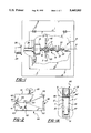
- FIG. 1 is a schematic front view of a fillet rolling machine illustrating some basic principals of fillet rolling employed in the present invention
- FIG. 1A is an enlarged view of a portion of FIG. 1 showing tooling rolling the fillets of a crank pin journal;
- FIG. 1B is a pictorial view of a portion of a crankshaft with connecting rods mounted side-by-side on juxtapositioned pin journals;
- FIG. 2 is a schematic view of a portion of the machine of FIG. 1 taken generally along sight lines 2--2 of FIG. 1;
- FIG. 3 is a pictorial view of one preferred embodiment of a fillet rolling machine according to this invention.
- FIG. 4 is a side view of the fillet rolling machine of FIG. 3;
- FIG. 4A is a pictorial view of a portion of a crankshaft for an internal combustion engine having arcuately offset and side-by-side crank pin journals;
- FIG. 4B is a diagram of the arcuately offset crank pin journals of FIG. 4A crankshaft
- FIG. 4C is a cross-sectional view taken along sight lines 4c--4c of FIG. 4.
- FIG. 5 is an end view with parts broken away of the fillet rolling machine of FIG. 4 as seen from view arrow A of FIG. 4.
- FIG. 6 is an enlarged side elevational view of tooling used in the fillet rolling machine of FIGS. 3, 4 and 5;
- FIG. 7 is a sectional view of the tooling of FIG. 5 taken along sight lines 7--7 of FIG. 6 but with a portion of the engine crank and back-up lower tooling added;
- FIG. 8 is a side elevational view of lower support tooling used for the fillet rolling machine of FIG. 4;
- FIG. 8A and 8B are cross-sectional views of the lower support tooling respectively taken along sight lines 8A--8A and 8B--8B of FIG. 8;
- FIG. 9 is a diagram illustrating the rolling of arcuately offset pin fillets according to this invention.
- FIGS. 1 and 2 diagrammatically show portions of a metal working machine 10 illustrating some principals of deep roll strengthening of the fillets of crank pins 12 of a crankshaft 14 for an internal combustion engine.
- the crankshaft has a nose end 16 mounted in a chuck 18 and a flange end 20 supported by a dead point center 22 of the machine.
- the crankshaft can be selectively and rotatably driven about horizontal axis B by a drive motor 24 supported by a mounting collar 26 on the machine housing and drivingly connected to the chuck by drive shaft 28.
- Each of the crank pins 12 have side-by-side and coaxial journal portions 30 and 32 (FIG. 1A) providing cylindrical bearings for the connecting rods 34, 36 (FIG. 1B) of opposing pistons in the left and right cylinders of V-block engines.
- pin journal portions 30, 32 experience high stress loads during engine operation, they are strengthened in various ways such as by increasing pin journal diameters and by deep roll hardening their laterally spaced annular fillets F, F' in which high and concentrated rolling forces are directed to annular fillet areas of the crankshaft.
- Such rolling produces compressive strengthening stresses in the metal of the crankshaft fillets that may, for example, extend to a depth of 4 mm.
- the upper tool 40 has a pair of floating rollers 46, 46' of hardened steel or other suitable material which generally turn on oppositely inclined axes "A and A"" to engage and roll the laterally spaced fillets F, F' providing the annular joint areas between the pins and the adjacent counter weights or bearing collars of the crankshaft.
- the lower tool 41 has arcuately spaced back-up rollers 47 that provide the bearing and support for the crank pins as the crankshaft 14 is being rotatably driven about its axis B and the fillets are being rolled.
- Rolling pressure is hydraulically applied by the expansion force of a hydraulic cylinder 48 operatively connected between the extending ends 49, 50 of the upper and lower jaw arms 51, 52 pivoted together by a clevis mounted pivot 53 disposed at an intermediate position along the jaw arm lengths.
- This arrangement provides the mechanical advantage that amplifies the jaw closure force exerted to the jaw assembly by the expansion force of the hydraulic power cylinder 48.
- the upper and lower jaws and their tools are supported to float around the axis of the orbiting crank pins during rolling.
- Rolling pressure exerted by the rollers 46, 46' can be increased and decreased by cylinder 48 during rotational drive of the crankshaft by motor 24 to impart concentrated annular residual stress patterns in the metal of the fillets F, F' which are among the most highly stressed cross-sectional areas of the crankshaft in engine operation.
- the amount of pressure as well as the number of over rolls of the fillets can be preselected to produce an optimized fatigue strength.
- crankshafts 54 having crank pins 55 with arcuately offset and contiguous crank pin journals 56, 58 (FIG. 4A) employed in many modern "V" block engines.
- the present invention exemplified in a first preferred embodiment in FIGS. 3 through 9, has been devised.
- the machine 60 of this invention has a pair of side-by-side uprights 62 and 64 extending upwardly from a base 66 that is adjustably mounted by tongue and groove or other rail construction to a support plate 70.
- This rail construction and connected power cylinder 72 allows the machine and its tooling to be readily moved into and out of engagement with the arcuately offset pin journals 56,58 of the crankshaft 54 when loaded into a drive chuck and dead point center as in FIG. 1.
- a pivot shaft 76 extends axially through the cylindrical support 74 and has a terminal end which fixedly supports the ends of right and left hand pairs of swing arms 78, 78' and 80, 80', which depend therefrom.
- the terminal ends of the swing arms carry support pivots 82 and 84 that respectively pivotally connect to the upper right and left hand jaw arms 88 and 90 that respectively extend between their associated pairs of swing arms.
- the upper right hand jaw arm 88 is pivotally connected to a lower right hand jaw arm 92 by an intermediate horizontally extending pivot 93. This pivot is supported by clevis 94 whose ears extend upwardly from the lower jaw arm to bracket the upper jaw arm.
- This construction provides a right hand clamping jaw set or assembly 95.
- the upper left hand jaw arm 90 is similarly connected by a clevis and pivot pin 96 to a lower left hand jaw arm 97 to provide a left hand jaw set or assembly 98.
- the right and left jaw arm clevises respectively receive downwardly extending lower portions of the upper jaw arms therebetween so that the upper and lower jaw arms of each pair are co-planar when pivotally connected by pivots 93 and 96 respectively.
- each jaw assembly is made from flat metal plate stock and have rearwardly extending portions 100, 102 and 104,106 that provide connection points for the clevises and pivot pins 108, 110, 112, 114 for right and left hydraulic power cylinders 116, 118.
- Each power cylinder has a cylinder tube in which a piston 120 or 122 is operatively mounted.
- Controls 123 controls the supply and exhaust of pressure fluid to the cylinders below and above the pistons to effect the expansion and contraction strokes of the cylinders so that the forwardly extending jaws 124, 126 and 128, 130 of the right and left hand pairs of jaw arms respectively close or open.
- the cylinders and pistons contract to turn the jaw arms on pivots 93 and 96 so that the jaws move to an open position apart from one another. This enables the tooling to be moved into working position with the crank pin journals 56, 58 or the crank removed from the tooling.
- FIG. 4C illustrates a spacing arrangement to maintain the relatively movable upper jaw arms 88, 90 in a parallel and laterally spaced relationship with respect to one another.
- This arrangement includes a cylindrically headed spacer element 111 having a cylindrical shank 111' extending axially through a corresponding close fit opening 113 in upper left hand arm 90 and through a large dimensioned opening 117 in the right hand upper arm 88. Secured by threaded fasteners to the upper arm 88 around the opening are inboard and outboard brass wear rings 121, 121'.
- An enlarged annular washer 125 secured to the outboard end of the retainer shank by a through bolt 133 has siding contact with the outer brass ring.
- the upper jaw 124, 128 of each upper jaw arm 88, 90 provides a seat for a pin fillet rolling tool assembly 134 shown best in FIGS. 6 and 7.
- the fillet rolling tool assembly 134 comprises a pair of tool housings 136 and 138 mounted in a side-by-side and relatively rotatable relationship with respect to one another. Retention clamps such as 131 and 132 secure the housings to the respective upper jaws 124 and 126.
- the housing 136 comprises an outboard rectangular main body 140 that has been milled or otherwise formed to provide an annular recess 142 that receives a back up roller 144 rotatably mounted therein by needle bearings 146 fitted on an inner cylindrical race 148, race 148 is supported on a large axially extending diameter hub 150 shouldered at 152 to fit into an annular opening in the outboard side of the main body 140.
- the housing 136 is closed at its inboard side by a annular cover plate 154 which is secured to the housing by threaded fasteners 156.
- the cover plate 154 has an enlarged annular recess 158 to receive the inboard end of the cylindrical hub 150.
- An annular cage of needle thrust bearings 160 supported on an internal shoulder of the cover plate concentric with the hub journal 150 is disposed between the back up roller and the cover plate and is adapted to transmit side loads resulting from the rolling of the fillets to an annular ball bearing unit 162 operatively disposed between the tool housings 136 and 138.
- the spherical balls 163 of this ball bearing unit are supported for rotation in cages in a support plate 164 operatively mounted on a centralized hub 166 extending axially from the cover plate 168 of adjacent tool housing 138.
- the spherical balls 163 roll in annular dished out bearing surfaces 170, 172 in the interfacing cover plates 154 and 168.
- Each housing 136, 138 has a pair of L-shaped work roller retainers 176, 178 and 180, 182 adjustably secured to the lower end thereof by threaded fasteners 184,184'. These retainers have inboard ends which are recessed to provide cages 186, 188. When the retainers are secured to their housings the cages support the hardened working rollers 190, 192 for floating rotation generally about upwardly and outwardly inclined axes 194, 196 so that the working circumference of the rollers extend to the fillets F and F' of the crank pin journals 56,58 being rolled.
- the work rollers 190, 192 are contacted by the annular stepped shoulders 197, 198 of backup rollers 144, 199 of housings 136, 138 respectively so that jaws when clamped will transmit a rolling force to the fillets F, F' as shown in FIG. 7.
- first and second steady rest units 200 and 202 which are respectively operatively mounted to the lower jaws such as by adjustable clamps 204,206 of each lower jaw arm. Since these units have substantially the same construction only unit 200 is described in particularly detail.
- Unit 200 has a generally rectilinear main body 203 with peripheral grooves 204, 206 which receive the edges of the plate of the lower jaw arm 92. Clamps 205 and 207 secure the unit 200 in position on the lower arm.
- Tool 200 has a pair of spaced rollers 208 and 210 which are rotatably mounted by needle bearings 209, 211 on hubs 212,214 supported by laterally spaced side plates 216, 218. Threaded fasteners 219 secure the side plates to the main body 203.
- pneumatic cylinders 222, 224 secured by bracket 226 to the cylindrical support 74 are employed.
- the cylinders 222, 224 respectively have pistons with rods 228, 230 extending downwardly which are pivotally connected to the upper jaw arms by bracket 230, 231 to control operation of the jaws and to stabilize the jaw arms when the fillets are being rolled.
- Element 232 is a rotor fixed to rotatable shaft 76 which cooperating with caliper 233 provides a disc brake 234 that can be selectively applied to hold the pairs of jaws in any selected position.
- the crankshaft 54 is placed into the chuck and center pin, as shown in FIG. 1. Then the tooling of FIGS. 3 through 8 is moved into position so that the working rollers contact the fillets F, F' of the offset pin journals 56, 58 as shown in FIG. 7. The jaws are closed under load by the expanding cylinders so that the work rollers 190, 192 engage the fillets F, F' with a selected rolling force.
- the drive motor 24 is then energized so that the chuck will rotatably drive the crankshaft about its rotational axis such as axis B.
- This rotation causes the offset pin journals 56, 58 to move in a circular path or orbit clockwise about the axis B of the crankshaft as the shaft is being turned (see FIG. 9).
- the clamping jaws, being clamped to the offset pins follow the rotational path of the pins. Accordingly, when the pins rotate around the axis B of the crankshaft, each jaw assembly will float and the support arms 78, 78', 80, 80' swing backwards and forward as a pendulum allowing this movement.
- the rolling pressure of the jaws translated to the working rollers can be increased or otherwise varied to effect the simultaneous deep rolling of the fillets and the deep metal working of the fillet areas to effect the improved fatigue strength of fillets and of the crankshaft. Since the crank pins are offset from one another, each set of arms follows its associated crank pin so that the fillets of the crank pin are simultaneously rolled even though they are arcuately offset. During rolling, suitable lubricants are applied to the fillet areas to reduce friction and enhance rolling.
- the power cylinders can be contracted to open the jaws so that the finished crankshaft can be removed from the machine.
Landscapes
- Engineering & Computer Science (AREA)
- Mechanical Engineering (AREA)
- Life Sciences & Earth Sciences (AREA)
- Agronomy & Crop Science (AREA)
- Finish Polishing, Edge Sharpening, And Grinding By Specific Grinding Devices (AREA)
- Shafts, Cranks, Connecting Bars, And Related Bearings (AREA)
Priority Applications (6)
| Application Number | Priority Date | Filing Date | Title |
|---|---|---|---|
| US08/176,792 US5445003A (en) | 1994-01-03 | 1994-01-03 | Engine crank pin rolling equipment, rolling tool and method of rolling adjacent and offset crank pins |
| CA002138899A CA2138899C (en) | 1994-01-03 | 1994-12-22 | Engine crank pin rolling equipment, rolling tool and method of rolling adjacent and offset crank pins |
| MX9500043A MX9500043A (es) | 1994-01-03 | 1995-01-02 | Equipo de forjado giratorio para pasador de cigüeñal de motor, herramienta de forjado giratorio y metodo de forjado giratorio de pasadores de cigüeñal adyacentes y desplazados. |
| DE59502019T DE59502019D1 (de) | 1994-01-03 | 1995-01-03 | Gerät zum Walzen von Motorenkurbelzapfen, Walzwerkzeug und Verfahren zum Walzen von aneinanderliegenden und versetzten Kurbelzapfen |
| EP95100047A EP0661137B1 (de) | 1994-01-03 | 1995-01-03 | Gerät zum Walzen von Motorenkurbelzapfen, Walzwerkzeug und Verfahren zum Walzen von aneinanderliegenden und versetzten Kurbelzapfen |
| US08/374,029 US5575167A (en) | 1994-01-03 | 1995-01-18 | Deep rolling split-pin fillets of crankshafts |
Applications Claiming Priority (1)
| Application Number | Priority Date | Filing Date | Title |
|---|---|---|---|
| US08/176,792 US5445003A (en) | 1994-01-03 | 1994-01-03 | Engine crank pin rolling equipment, rolling tool and method of rolling adjacent and offset crank pins |
Related Child Applications (1)
| Application Number | Title | Priority Date | Filing Date |
|---|---|---|---|
| US08/374,029 Continuation-In-Part US5575167A (en) | 1994-01-03 | 1995-01-18 | Deep rolling split-pin fillets of crankshafts |
Publications (1)
| Publication Number | Publication Date |
|---|---|
| US5445003A true US5445003A (en) | 1995-08-29 |
Family
ID=22645843
Family Applications (1)
| Application Number | Title | Priority Date | Filing Date |
|---|---|---|---|
| US08/176,792 Expired - Lifetime US5445003A (en) | 1994-01-03 | 1994-01-03 | Engine crank pin rolling equipment, rolling tool and method of rolling adjacent and offset crank pins |
Country Status (5)
| Country | Link |
|---|---|
| US (1) | US5445003A (de) |
| EP (1) | EP0661137B1 (de) |
| CA (1) | CA2138899C (de) |
| DE (1) | DE59502019D1 (de) |
| MX (1) | MX9500043A (de) |
Cited By (23)
| Publication number | Priority date | Publication date | Assignee | Title |
|---|---|---|---|---|
| US5575167A (en) * | 1994-01-03 | 1996-11-19 | Hegenscheidt Corporation | Deep rolling split-pin fillets of crankshafts |
| US5577401A (en) * | 1995-11-15 | 1996-11-26 | Monarch Knitting Machinery Corp. | Knitting machine cylinder having a hardened top insert ring and method of making same |
| US5699692A (en) * | 1996-10-30 | 1997-12-23 | Lonero Engineering Co., Inc. | Tool mechanisms for deep rolling machines |
| US5806184A (en) * | 1996-08-21 | 1998-09-15 | Lonero Engineering Company, Inc. | Process to manufacture upper work roll products |
| WO1998051432A1 (en) * | 1997-05-16 | 1998-11-19 | Hegenscheidt-Mfd Corporation | Support tool for deep rolling crankshaft fillets |
| US5943893A (en) * | 1997-05-28 | 1999-08-31 | Hegenscheidt-Mfd Gmbh | Roll-hardening machine for crankshafts |
| US6272896B1 (en) | 1999-12-23 | 2001-08-14 | Daimlerchrysler Corporation | Secondary (back-up) roller design for the fillet rolling of the crankshaft |
| US6389861B1 (en) * | 2000-08-28 | 2002-05-21 | Hegenscheidt-Mfd Gm H & Co. Kg | Roller cage |
| US6393885B1 (en) | 2000-11-07 | 2002-05-28 | Hegenscheidt Mfd Corporation | Tooling for deep rolling fillets of crankshaft journals |
| US6393887B1 (en) * | 1999-06-11 | 2002-05-28 | Hegenscheidt-Mfd Gmbh & Co., Kg | Roll-hardening device pertaining to a roll-hardening machine for crankshafts |
| WO2002042018A1 (en) * | 2000-11-22 | 2002-05-30 | Ingersoll Cm Systems, Inc. | Apparatus and method for rolling workpieces |
| US6666061B2 (en) | 2001-05-28 | 2003-12-23 | Hegenscheidt-Mfd Gmbh & Co. Kg | Apparatus for deep rolling of recesses and radii of crankshaft journal bearings |
| EP1468786A1 (de) * | 2003-04-18 | 2004-10-20 | Vincent J. Lonero | Zweiteiliges oberes Walzwerkzeug |
| US20050086988A1 (en) * | 2002-07-05 | 2005-04-28 | Derichs Heinrich W. | Deep rolling head |
| US20060000254A1 (en) * | 2004-06-01 | 2006-01-05 | Ingersoll Cm Systems Llc | Apparatus and method of rolling split pin crankshafts |
| WO2006058557A1 (de) * | 2004-12-04 | 2006-06-08 | Hegenscheidt-Mfd Gmbh & Co. Kg | Festwalzrollenkopf |
| US20060225478A1 (en) * | 2005-04-07 | 2006-10-12 | Mella Ramon A | Method for straightening an eccentric shaft |
| US20070048098A1 (en) * | 2005-08-31 | 2007-03-01 | Ingersoll Cm Systems Llc | Method and apparatus for machining crankshafts or camshafts |
| JP2007152536A (ja) * | 2005-12-08 | 2007-06-21 | Fuji Heavy Ind Ltd | フィレットロール加工機 |
| US7493788B2 (en) | 2003-12-09 | 2009-02-24 | Hegenscheidt-Mfd Gmbh & Co. Kg | Deep rolling roller head for split-pin crankshafts |
| US20120096696A1 (en) * | 2005-04-01 | 2012-04-26 | Hegenscheidt-Mfd Gmbh & Co. Kg | Roller Burnishing Machine For Crankshafts |
| US20140041433A1 (en) * | 2012-08-09 | 2014-02-13 | Ingersoll CM Systems | Rolling tool assemblies for crankshaft rolling machines |
| CN104148878A (zh) * | 2014-08-08 | 2014-11-19 | 滨州海得曲轴有限责任公司 | 一种曲轴摆动滚压装置 |
Families Citing this family (7)
| Publication number | Priority date | Publication date | Assignee | Title |
|---|---|---|---|---|
| DE10060218A1 (de) * | 2000-12-04 | 2002-06-13 | Hegenscheidt Mfd Gmbh & Co Kg | Festwalzmaschine für Kurbelwellen |
| DE10141119B4 (de) * | 2001-08-22 | 2005-01-27 | Hegenscheidt-Mfd Gmbh & Co. Kg | Festwalzwerkzeug |
| DE10209301C1 (de) * | 2002-03-02 | 2003-03-27 | Hegenscheidt Mfd Gmbh & Co Kg | Vorrichtung zum Einstellen von Festwalzrollen |
| US7168278B2 (en) * | 2002-04-26 | 2007-01-30 | Hegenscheidt-Mfd Gmbh | Deep rolling roller head of a deep rolling tool |
| DE102005021793B4 (de) * | 2005-05-11 | 2007-03-29 | Maschinenfabrik Alfing Kessler Gmbh | Verfahren und Anlage zum Härten von Übergangsradien einer Welle |
| DE202016001445U1 (de) | 2016-03-02 | 2017-06-06 | Hegenscheidt-Mfd Gmbh | Festwalzrollenkopf zum Festwalzen von Hubzapfen einer Split-Pin-Kurbelwelle |
| CN118268452B (zh) * | 2024-06-03 | 2024-08-30 | 四川明泰微电子科技股份有限公司 | 一种翻转式切筋模具及切筋装置 |
Citations (6)
| Publication number | Priority date | Publication date | Assignee | Title |
|---|---|---|---|---|
| US4485537A (en) * | 1982-06-28 | 1984-12-04 | Wilhelm Hegenscheidt Gmbh | Machine for the machining of crankshafts |
| US4554811A (en) * | 1983-08-04 | 1985-11-26 | Toyoda Koki Kabushiki Kaisha | Crankpin rolling apparatus |
| US4559798A (en) * | 1984-07-09 | 1985-12-24 | Toyoda Koki Kabushiki Kaisha | Fillet rolling machine |
| US4766753A (en) * | 1985-08-30 | 1988-08-30 | W. Hegenscheidt Gmbh | Rolling apparatus for surface hardening or smoothing |
| US5138859A (en) * | 1990-06-15 | 1992-08-18 | Firma Wilhelm Hegenscheidt Gesellschaft Mbh | Method and apparatus for smooth-rolling and deep-rolling multi-stroke crankshafts |
| US5235838A (en) * | 1987-07-13 | 1993-08-17 | W. Hegenscheidt Gesellschaft Mbh | Method and apparatus for truing or straightening out of true work pieces |
Family Cites Families (1)
| Publication number | Priority date | Publication date | Assignee | Title |
|---|---|---|---|---|
| DE3728013A1 (de) * | 1987-08-22 | 1989-03-02 | Daimler Benz Ag | Kurbeltrieb einer brennkraftmaschine der v-bauart |
-
1994
- 1994-01-03 US US08/176,792 patent/US5445003A/en not_active Expired - Lifetime
- 1994-12-22 CA CA002138899A patent/CA2138899C/en not_active Expired - Fee Related
-
1995
- 1995-01-02 MX MX9500043A patent/MX9500043A/es unknown
- 1995-01-03 DE DE59502019T patent/DE59502019D1/de not_active Expired - Fee Related
- 1995-01-03 EP EP95100047A patent/EP0661137B1/de not_active Expired - Lifetime
Patent Citations (6)
| Publication number | Priority date | Publication date | Assignee | Title |
|---|---|---|---|---|
| US4485537A (en) * | 1982-06-28 | 1984-12-04 | Wilhelm Hegenscheidt Gmbh | Machine for the machining of crankshafts |
| US4554811A (en) * | 1983-08-04 | 1985-11-26 | Toyoda Koki Kabushiki Kaisha | Crankpin rolling apparatus |
| US4559798A (en) * | 1984-07-09 | 1985-12-24 | Toyoda Koki Kabushiki Kaisha | Fillet rolling machine |
| US4766753A (en) * | 1985-08-30 | 1988-08-30 | W. Hegenscheidt Gmbh | Rolling apparatus for surface hardening or smoothing |
| US5235838A (en) * | 1987-07-13 | 1993-08-17 | W. Hegenscheidt Gesellschaft Mbh | Method and apparatus for truing or straightening out of true work pieces |
| US5138859A (en) * | 1990-06-15 | 1992-08-18 | Firma Wilhelm Hegenscheidt Gesellschaft Mbh | Method and apparatus for smooth-rolling and deep-rolling multi-stroke crankshafts |
Cited By (35)
| Publication number | Priority date | Publication date | Assignee | Title |
|---|---|---|---|---|
| US5575167A (en) * | 1994-01-03 | 1996-11-19 | Hegenscheidt Corporation | Deep rolling split-pin fillets of crankshafts |
| US5577401A (en) * | 1995-11-15 | 1996-11-26 | Monarch Knitting Machinery Corp. | Knitting machine cylinder having a hardened top insert ring and method of making same |
| US6159135A (en) * | 1996-08-21 | 2000-12-12 | Lonero Engineering, Inc. | Work roller for use in deep rolling process of crankshafts or like products |
| US5806184A (en) * | 1996-08-21 | 1998-09-15 | Lonero Engineering Company, Inc. | Process to manufacture upper work roll products |
| EP0839607A1 (de) * | 1996-10-30 | 1998-05-06 | Lonero engineering Co., Inc | Werkzeugvorrichtung für Teifwalzmaschinen |
| US5699692A (en) * | 1996-10-30 | 1997-12-23 | Lonero Engineering Co., Inc. | Tool mechanisms for deep rolling machines |
| WO1998051432A1 (en) * | 1997-05-16 | 1998-11-19 | Hegenscheidt-Mfd Corporation | Support tool for deep rolling crankshaft fillets |
| US6094956A (en) * | 1997-05-16 | 2000-08-01 | Hegenschiedt-Mfd Corporation | Support tool for deep rolling crankshaft fillets |
| US5943893A (en) * | 1997-05-28 | 1999-08-31 | Hegenscheidt-Mfd Gmbh | Roll-hardening machine for crankshafts |
| US6393887B1 (en) * | 1999-06-11 | 2002-05-28 | Hegenscheidt-Mfd Gmbh & Co., Kg | Roll-hardening device pertaining to a roll-hardening machine for crankshafts |
| US6272896B1 (en) | 1999-12-23 | 2001-08-14 | Daimlerchrysler Corporation | Secondary (back-up) roller design for the fillet rolling of the crankshaft |
| US6389861B1 (en) * | 2000-08-28 | 2002-05-21 | Hegenscheidt-Mfd Gm H & Co. Kg | Roller cage |
| US6393885B1 (en) | 2000-11-07 | 2002-05-28 | Hegenscheidt Mfd Corporation | Tooling for deep rolling fillets of crankshaft journals |
| WO2002042018A1 (en) * | 2000-11-22 | 2002-05-30 | Ingersoll Cm Systems, Inc. | Apparatus and method for rolling workpieces |
| US7387008B2 (en) | 2000-11-22 | 2008-06-17 | Ingersoll Cm Systems, Inc. | Apparatus and method for rolling workpieces |
| US20050145000A1 (en) * | 2000-11-22 | 2005-07-07 | Heffron Allan J. | Apparatus and method for rolling workpieces |
| US6666061B2 (en) | 2001-05-28 | 2003-12-23 | Hegenscheidt-Mfd Gmbh & Co. Kg | Apparatus for deep rolling of recesses and radii of crankshaft journal bearings |
| US20050086988A1 (en) * | 2002-07-05 | 2005-04-28 | Derichs Heinrich W. | Deep rolling head |
| US7100413B2 (en) | 2002-07-05 | 2006-09-05 | Hegenscheidt-Mfd Gmbh & Co. Kg | Deep-rolling roller head |
| EP1468786A1 (de) * | 2003-04-18 | 2004-10-20 | Vincent J. Lonero | Zweiteiliges oberes Walzwerkzeug |
| US7493788B2 (en) | 2003-12-09 | 2009-02-24 | Hegenscheidt-Mfd Gmbh & Co. Kg | Deep rolling roller head for split-pin crankshafts |
| US20060000254A1 (en) * | 2004-06-01 | 2006-01-05 | Ingersoll Cm Systems Llc | Apparatus and method of rolling split pin crankshafts |
| US7188500B2 (en) | 2004-06-01 | 2007-03-13 | Ingersoll Cm Systems Llc | Apparatus and method of rolling split pin crankshafts |
| WO2006058557A1 (de) * | 2004-12-04 | 2006-06-08 | Hegenscheidt-Mfd Gmbh & Co. Kg | Festwalzrollenkopf |
| US20080209969A1 (en) * | 2004-12-04 | 2008-09-04 | Hegenscheidt-Mfd Gmbh & Co. Kg | Deep Rolling Head |
| US20120096696A1 (en) * | 2005-04-01 | 2012-04-26 | Hegenscheidt-Mfd Gmbh & Co. Kg | Roller Burnishing Machine For Crankshafts |
| US8245374B2 (en) * | 2005-04-01 | 2012-08-21 | Hegenscheidt-Mfd Gmbh & Co. Kg | Roller burnishing machine for crankshafts |
| US20060225478A1 (en) * | 2005-04-07 | 2006-10-12 | Mella Ramon A | Method for straightening an eccentric shaft |
| US7188497B2 (en) | 2005-04-07 | 2007-03-13 | International Engine Intellectual Property Company, Llc | Method for straightening an eccentric shaft |
| US20070048098A1 (en) * | 2005-08-31 | 2007-03-01 | Ingersoll Cm Systems Llc | Method and apparatus for machining crankshafts or camshafts |
| US7588397B2 (en) | 2005-08-31 | 2009-09-15 | Ingersoll Cm Systems Llc | Method and apparatus for machining crankshafts or camshafts |
| JP4658789B2 (ja) * | 2005-12-08 | 2011-03-23 | 富士重工業株式会社 | フィレットロール加工機 |
| JP2007152536A (ja) * | 2005-12-08 | 2007-06-21 | Fuji Heavy Ind Ltd | フィレットロール加工機 |
| US20140041433A1 (en) * | 2012-08-09 | 2014-02-13 | Ingersoll CM Systems | Rolling tool assemblies for crankshaft rolling machines |
| CN104148878A (zh) * | 2014-08-08 | 2014-11-19 | 滨州海得曲轴有限责任公司 | 一种曲轴摆动滚压装置 |
Also Published As
| Publication number | Publication date |
|---|---|
| EP0661137B1 (de) | 1998-04-29 |
| CA2138899A1 (en) | 1995-07-04 |
| MX9500043A (es) | 1997-06-28 |
| CA2138899C (en) | 1999-01-05 |
| DE59502019D1 (de) | 1998-06-04 |
| EP0661137A1 (de) | 1995-07-05 |
Similar Documents
| Publication | Publication Date | Title |
|---|---|---|
| US5445003A (en) | Engine crank pin rolling equipment, rolling tool and method of rolling adjacent and offset crank pins | |
| US6393885B1 (en) | Tooling for deep rolling fillets of crankshaft journals | |
| US5575167A (en) | Deep rolling split-pin fillets of crankshafts | |
| US20100147044A1 (en) | Method and device for reinforcing crankshafts | |
| CA2149182C (en) | Metal rolling machine with opposing banks of jaw units for working a centered workpiece and method of rolling annular fillets of workpieces | |
| CN103447778A (zh) | 一种重卡发动机曲轴的加工工艺 | |
| CN101198441A (zh) | 用于加工曲轴的方法和装置以及用于曲轴的抛光辊 | |
| EP1126951B1 (de) | Verfahren und vorrichtung zum prägepolieren zum herstellen einer restdruckspannung über eine werkstückfläche | |
| US6094956A (en) | Support tool for deep rolling crankshaft fillets | |
| US20090307886A1 (en) | Method and Device for Processing Crankshaft and Burnishing Roller for Crankshaft | |
| CN100519052C (zh) | 在曲轴支承轴颈和凸缘之间的过渡区进行深度轧制的方法 | |
| US7150173B2 (en) | Upper and lower tools for deep rolling | |
| US3823588A (en) | Method and system for straightening large diameter shafts by selective cold rolling | |
| SU878510A1 (ru) | Устройство дл обработки абразивным инструментом | |
| EP1426139B1 (de) | Vorrichtung zum Prägepolieren zum Herstellen einer Restdruckspannung über einer Werkstückfläche | |
| US6434992B1 (en) | Fillet rolling support roller | |
| CN210498779U (zh) | 一种焊接修复装置 | |
| CN209969855U (zh) | 一种熔覆修复装置 | |
| CN202763384U (zh) | 单缸曲轴滚压机床 | |
| US6354920B1 (en) | Centerless camshaft microfinishing machine | |
| CN209974845U (zh) | 一种去应力装置 | |
| CN209974894U (zh) | 一种熔覆预定型装置 | |
| JP5256327B2 (ja) | クランク軸の疲労強度改善加工方法とその加工装置 | |
| CN209977204U (zh) | 一种传动装置 | |
| JP2729949B2 (ja) | バニシ加工工具 |
Legal Events
| Date | Code | Title | Description |
|---|---|---|---|
| AS | Assignment |
Owner name: HEGEN SCHEIDT CORPORATION, MICHIGAN Free format text: ASSIGNMENT OF ASSIGNORS INTEREST;ASSIGNORS:GOTTSCHALK, WILLIAM P.;LAUTEN, HANS T.;REEL/FRAME:006846/0530 Effective date: 19940103 |
|
| STCF | Information on status: patent grant |
Free format text: PATENTED CASE |
|
| FPAY | Fee payment |
Year of fee payment: 4 |
|
| FPAY | Fee payment |
Year of fee payment: 8 |
|
| FPAY | Fee payment |
Year of fee payment: 12 |