US5444317A - Braking mechanism for a shaded-pole motor - Google Patents
Braking mechanism for a shaded-pole motor Download PDFInfo
- Publication number
- US5444317A US5444317A US08/151,928 US15192893A US5444317A US 5444317 A US5444317 A US 5444317A US 15192893 A US15192893 A US 15192893A US 5444317 A US5444317 A US 5444317A
- Authority
- US
- United States
- Prior art keywords
- rotor
- pawl
- pole piece
- motor
- arm
- Prior art date
- Legal status (The legal status is an assumption and is not a legal conclusion. Google has not performed a legal analysis and makes no representation as to the accuracy of the status listed.)
- Expired - Fee Related
Links
- 230000007246 mechanism Effects 0.000 title abstract description 18
- 230000004907 flux Effects 0.000 claims description 9
- 230000000694 effects Effects 0.000 claims 2
- 239000002184 metal Substances 0.000 claims 2
- 238000010276 construction Methods 0.000 description 5
- 210000005069 ears Anatomy 0.000 description 2
- 238000004519 manufacturing process Methods 0.000 description 2
- 230000004048 modification Effects 0.000 description 2
- 238000012986 modification Methods 0.000 description 2
- 230000035939 shock Effects 0.000 description 2
- 229910000831 Steel Inorganic materials 0.000 description 1
- 238000004026 adhesive bonding Methods 0.000 description 1
- 230000002411 adverse Effects 0.000 description 1
- 230000000295 complement effect Effects 0.000 description 1
- 238000002347 injection Methods 0.000 description 1
- 239000007924 injection Substances 0.000 description 1
- 238000003475 lamination Methods 0.000 description 1
- 239000000696 magnetic material Substances 0.000 description 1
- 239000000463 material Substances 0.000 description 1
- 230000002093 peripheral effect Effects 0.000 description 1
- 239000010959 steel Substances 0.000 description 1
Images


Classifications
-
- H—ELECTRICITY
- H02—GENERATION; CONVERSION OR DISTRIBUTION OF ELECTRIC POWER
- H02K—DYNAMO-ELECTRIC MACHINES
- H02K7/00—Arrangements for handling mechanical energy structurally associated with dynamo-electric machines, e.g. structural association with mechanical driving motors or auxiliary dynamo-electric machines
- H02K7/10—Structural association with clutches, brakes, gears, pulleys or mechanical starters
- H02K7/102—Structural association with clutches, brakes, gears, pulleys or mechanical starters with friction brakes
- H02K7/1021—Magnetically influenced friction brakes
- H02K7/1026—Magnetically influenced friction brakes using stray fields
Definitions
- This invention relates to a shaded-pole motor and, more particularly, to a shaded-pole motor having a mechanical brake for stopping the rotor of the motor when the motor is de-energized.
- the assignee of the present invention has sold shaded-pole motors with brakes for automatically stopping the rotor upon de-energization of the motor.
- the prior brake comprises a pivotally mounted pawl and a separately pivotally mounted pole piece.
- the pole piece When the motor is energized, the pole piece is magnetically attracted to the laminated core of the stator of the motor and, upon being so attracted, swings about its pivot and forces the pawl to swing about its pivot to a released position in which the pawl clears a stop lug on the rotor so as to permit rotation of the rotor.
- a spring Upon de-energization of the motor, a spring swings the pole piece reversely about its pivot so as to cause the pawl to swing reversely around its pivot to a braking position in which the pawl engages the stop lug on the rotor in order to apply a braking force to the rotor.
- the prior brake requires several components and thus is relatively expensive to manufacture and assemble. Moreover, the prior brake requires one set of components if the rotor is rotated in a clockwise direction and a different set of components if the rotor is rotated in a counterclockwise direction. Accordingly, tooling costs and inventory requirements are comparatively high.
- the general aim of the present invention is to provide a new and improved shaded-pole motor brake which, when compared to prior brakes of the same general type, may be manufactured and assembled on a more economical basis.
- a related object of the invention is to provide a brake whose components may be used universally with motors having rotors which rotate either clockwise or counterclockwise.
- a more detailed object is to achieve the foregoing by providing a brake in which the pawl and the pole piece are essentially a single unit mounted to swing about a single pivot and in which the unit may be reversed for mounting on either side of the rotor depending upon the direction of rotation of the rotor.
- the invention also resides in the provision of a pole piece which reduces shunting of magnetic flux from the rotor when the pole piece is attracted to the laminated stator core.
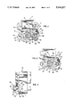
- FIG. 1 is a front elevational view of a typical shaded-pole motor with a clockwise rotatable rotor and equipped with a new and improved brake incorporating the unique features of the present invention, certain parts of the motor being broken away and the brake being shown in a released position.
- FIG. 2 is a view similar to FIG. 1 but shows the brake in an active braking position.
- FIG. 3 is a fragmentary side elevational view of the motor shown in FIG. 1.
- FIG. 4 is an exploded perspective view of certain components of the motor.
- FIG. 5 is an exploded perspective view of certain other components of the motor.
- FIG. 6 is a view similar to FIG. 1 but shows a motor having a counterclockwise rotatable rotor and a brake for stopping rotation of that rotor.
- FIGS. 7 and 8 are views similar to FIGS. 4 and 5, respectively, but show the components of the motor and brake of FIG. 6.
- the motor includes a stator 11 with a generally rectangular laminated core 12, a rotor 13 rotatable in a cylindrical recess in the core, and a field coil 14 mounted on one leg of the core and adapted to be energized by a.c. voltage to produce magnetic flux creating a magnetic field in the core.
- two sets of shading rings or coils 15 and 16 are supported by the core 12 on the pole thereof to shade or suppress a component of the field in order to cause the latter to revolve around the rotor and produce starting torque.
- the coils 15 and 16 are short-circuited and cause the rotor of the motor of FIGS. 1-5 to rotate in a clockwise direction by virtue of the field moving from the main pole area to the shaded area.
- the core 12 is notched as indicated at 18 in FIG. 1 to reduce the lamination area in the vicinity of the notch and cause rapid saturation to force the majority of the flux through the rotor.
- the rotor 13 comprises a cylindrical core carrying a plurality of conducting bars 19 that are fitted in peripheral slots equally spaced around the core and are connected by conducting discs at their ends.
- the rotor includes a central shaft 20 which is tightly received with a press fit or by adhesive bonding in a tubular hub 21 (FIG. 5) having a flange 22 at the outer end thereof.
- the shaft extends through the hub and is journaled in a bearing bracket 23 having two apertured ears 24 and 25 at its ends.
- Screws 26 and 27 extend through the ears and through holes 28 (FIG. 4) formed in the stator 11 and are threaded into a rear bearing bracket (not shown), thereby fastening the bearing bracket 23 to the stator.
- the motor 10 Upon de-energization of the field coil 14, the rotor tends to coast to a stop. In many applications, however, there is a need to brake the rotor to a stop when the field coil is de-energized.
- the motor 10 is equipped with a braking mechanism 30.
- the present invention contemplates a new and improved braking mechanism 30 which includes a relatively small number of components so as to enable economical manufacture and assembly of the braking mechanism. Moreover, the components of the braking mechanism are constructed such that the same mechanism may be used either with a motor with a clockwise rotatable rotor 13 or with a motor in which the rotor rotates in a counterclockwise direction.
- the braking mechanism 30 includes a braking member 31 (FIG. 5) which herein is in the form of a hard plastic ring telescoped rotatably over the hub 21.
- a stop lug 32 formed with an angled stop surface 33 which faces in a circumferential direction.
- the rotor 13 of the motor 10 shown in FIGS. 1-5 rotates in a clockwise direction and, in that motor, the stop surface 33 also faces in a clockwise direction.
- Two resiliently yieldable wave washers 34 are telescoped onto the hub 21 adjacent the inner end of the braking ring 31 and are sandwiched between the braking ring and a plain washer 35 which is fixed to the inner end portion of the hub by swaging the inner end of the hub.
- the wave washers press the ring 31 against a plain washer 36 which, in turn, is pressed against the flange 22 of the hub.
- the braking ring is frictionally coupled to the hub so as to normally rotate in unison with the hub.
- a pawl 40 for selectively engaging the stop surface 33 of the lug 32 in order to stop the rotor 13.
- the pawl is injection molded from a relatively hard plastic material and is formed integrally with and projects radially from a central tubular hub 41 (FIG. 4).
- the pawl is pivotally mounted on the stator 11 and, when the pawl is in an active braking position shown in FIG. 2, a tooth 42 on the pawl engages the stop surface 33 of the lug 32 to bring the rotor to a stop.
- the free end of the tooth is angled in accordance with the angle of the stop surface 33.
- the pawl is adapted to be pivoted clockwise from the braking position of FIG. 2 to a released position shown in FIG. 1. When the pawl is in the latter position, the tooth 42 clears the lug 32 to permit free rotation of the rotor.
- the pawl 40 is mounted on the stator 11 on the right hand side of the rotor 13.
- a bushing 45 (FIG. 4) with a radially extending flange 46 is supported by the screw 26 and is telescoped rotatably into the hub 41, the latter being sandwiched between the ear 24 and the flange 46.
- a contractile spring 47 biases the pawl 40 counterclockwise about the bushing 45 to its active braking position.
- One end of the spring is hooked into an apertured ear 48 molded integrally with the hub 21 and spaced angularly from the pawl.
- the other end of the spring is hooked into an outwardly extending and apertured ear 49 of a spring retaining element 50 having an upright plate 51 supported on the bushing 45 and sandwiched between the stator 11 and the flange 46.
- An anti-rotation pin 52 extends rearwardly from the plate 51 and projects into a hole 53 in the stator 11 to prevent turning of the spring retaining element 50.
- a pole piece 60 made of magnetic material is connected rigidly with the pawl 40 and coacts with the stator 11 to cause the pawl to swing to its released position when the field coil 14 is energized.
- the pole piece is flat and generally L-shaped and is stamped from steel.
- a mounting arm 61 is molded integrally with and projects radially from the hub 41 in angularly spaced relation with the pawl 40 and the ear 48.
- the lower end of the arm is formed with a recess which receives the short leg 63 of the pole piece 60.
- a plastic protrusion 64 projects downwardly from the lower end of the arm and through a hole (not visible) in the short leg of the pole piece.
- the lower end of the protrusion is staked over against the underside of the pole piece and serves to clamp the latter against the lower end of the arm.
- Other means may be used to fasten the pole piece to the arm.
- the long leg 65 of the pole piece 60 underlies the core 12 of the stator 11.
- the spring 47 biases the pole piece to an inactive position (FIG. 2) in which the pole piece is spaced from the lower side of the core.
- magnetic flux attracts the pole piece into engagement with the core as shown in FIG. 1.
- the pawl 40 is pivoted clockwise to its released position of FIG. 1.
- the length of the long leg 65 of the pole pieces 60 is such that the free end of the long leg is located short of the notch 18 in the core 12 when the pole piece is in its active position.
- the spring 47 biases the one-piece unit consisting of the pawl 40, the hub 41, the ear 48 and the arm 61 in a counterclockwise direction when the field coil 14 is de-energized.
- the free end of the tooth 42 of the pawl engages the stop surface 33 of the lug 32 to prevent rotation of the rotor 13, the long leg 65 of the pole piece 60 being spaced below the core 12 of the stator 11.
- the pawl is pivoted clockwise to a released position in which the pawl tooth 42 clears the lug 32 to permit free rotation of the rotor 13.
- the pawl tooth Upon de-energization of the field coil and counterclockwise pivoting of the pawl, the pawl tooth engages the lug to stop rotation of the braking ring 31 and cause friction between the ring 31, the washers 34-36, the hub flange 22 to bring the rotor to a stop without shock loads. If the rotor should happen to bounce counterclockwise after the lug hits the pawl tooth, the clockwise facing edge of the pawl tooth engages the counterclockwise facing surface of the lug to limit counterclockwise bouncing to less than one revolution.
- the aforementioned edge and surface are formed at complementary angles.
- the present invention brings to the art a braking mechanism 30 which is of relatively simple and inexpensive construction by virtue of the pawl 40, the hub 41 and the pole piece mounting arm 61 being formed as a single integral unit.
- This construction enables the braking mechanism to operate quieter (e.g., four db quieter) than prior braking mechanisms and enables the rotor to be stopped after one or two revolutions rather than two or more revolutions as is the case with prior mechanisms.
- FIGS. 6-8 show the braking mechanism installed on a motor having shading rings 15 and 16 which cause the rotor to rotate in a counterclockwise direction.
- the braking ring 31 is turned end-for-end through 180 degrees on the hub 21 so that the angled stop surface 33 of the stop lug 32 faces in a counterclockwise direction.
- the one-piece unit consisting of the pawl 40, the hub 41, the ear 48 and the arm 61 is turned end-for-end through 180 degrees and, along with the spring 47 and the spring retaining element 50, is attached to the stator 11 on the left side of the rotor 13 by the screw 27 and by virtue of the anti-rotation pin 52 of the retaining element projecting into a hole 70 (FIG. 1) in the left side of the stator.
- the spring retaining element does not require any reorientation when switched from the right side of the stator to the left side thereof.
- the pole piece 60 When the braking mechanism 30 is installed on the left side of the rotor 13, the pole piece 60 is both turned end-for-end and is inverted prior to being attached to the arm 61 by the protrusion 64. Thus, the long leg 65 of the pole piece 60 may remain positioned inwardly of the arm 61 but extends left-to-right from the arm rather than from right-to-left.
- the key to the universal applicability of the components of the braking mechanism 30 resides in the fact that the unit consisting of the pawl 40, the hub 41, the ear 48 and the arm 61 is symmetrical with respect to a radial plane extending midway between the ends of the hub. Also, the braking ring 31 and the stop lug 32 are symmetrical with respect to such plane. Thus, the components may be turned end-for-end for either clockwise or counterclockwise rotation of the rotor 13 without affecting the positions of the components relative to one another and without adversely affecting the positions of the components relative to the other parts of the motor 10.
- the components of the braking mechanism 30 may be used universally with motors 10 of either direction, the cost of tooling the components is reduced significantly when compared to "handed" braking mechanisms. Also, a fewer number of different components need be kept in inventory.
Landscapes
- Engineering & Computer Science (AREA)
- Power Engineering (AREA)
- Connection Of Motors, Electrical Generators, Mechanical Devices, And The Like (AREA)
Abstract
Description
Claims (11)
Priority Applications (1)
| Application Number | Priority Date | Filing Date | Title |
|---|---|---|---|
| US08/151,928 US5444317A (en) | 1993-11-15 | 1993-11-15 | Braking mechanism for a shaded-pole motor |
Applications Claiming Priority (1)
| Application Number | Priority Date | Filing Date | Title |
|---|---|---|---|
| US08/151,928 US5444317A (en) | 1993-11-15 | 1993-11-15 | Braking mechanism for a shaded-pole motor |
Publications (1)
| Publication Number | Publication Date |
|---|---|
| US5444317A true US5444317A (en) | 1995-08-22 |
Family
ID=22540847
Family Applications (1)
| Application Number | Title | Priority Date | Filing Date |
|---|---|---|---|
| US08/151,928 Expired - Fee Related US5444317A (en) | 1993-11-15 | 1993-11-15 | Braking mechanism for a shaded-pole motor |
Country Status (1)
| Country | Link |
|---|---|
| US (1) | US5444317A (en) |
Cited By (10)
| Publication number | Priority date | Publication date | Assignee | Title |
|---|---|---|---|---|
| US5847522A (en) * | 1995-11-13 | 1998-12-08 | Gec-Marconi Aerospace Inc. | Locking devices and control circuitry for permanent magnet electric motors |
| GB2344478A (en) * | 1995-11-13 | 2000-06-07 | Gec Marconi Aerospace Inc | Locking devices for electric motors |
| WO2000060722A1 (en) * | 1999-04-05 | 2000-10-12 | Fasco Industries, Inc. | Pawl brake assembly |
| US6573670B2 (en) | 2001-07-10 | 2003-06-03 | Merkle-Korff Industries, Inc. | Gearmotor with feedback control apparatus and method |
| US6731034B1 (en) * | 1998-12-28 | 2004-05-04 | Robert Bosch Gmbh | Electric motor with electromagnetic brake |
| US20040104239A1 (en) * | 2002-10-04 | 2004-06-03 | Black Talbert James | Vending machine dispensing system |
| US20050179330A1 (en) * | 2003-04-01 | 2005-08-18 | Michael Habele | Brake device for an electric motor |
| US7248008B1 (en) * | 2005-10-17 | 2007-07-24 | Cummins Michael D | Shaded-pole A.C. motor with dynamic brake |
| USD649983S1 (en) | 2008-11-14 | 2011-12-06 | Merkle-Korff Industries, Inc. | Gear motor assembly |
| US20180013332A1 (en) * | 2016-07-08 | 2018-01-11 | Akebono Brake Industry Co., Ltd | Motor with a motor brake |
Citations (9)
| Publication number | Priority date | Publication date | Assignee | Title |
|---|---|---|---|---|
| US2539836A (en) * | 1948-07-06 | 1951-01-30 | Raymond T Moloney | Electric motor brake |
| DE826010C (en) * | 1948-10-19 | 1951-12-27 | Mix & Genest A G | Electromotive drive device, especially for dialers in telecommunications systems |
| GB752328A (en) * | 1954-12-17 | 1956-07-11 | Lucien Charles Alexis Marie Bi | Improvements in or relating to electric motors for windscreen wipers |
| US3219858A (en) * | 1961-06-19 | 1965-11-23 | Nat Rejectors Gmbh | Money-actuated devices |
| US3344292A (en) * | 1964-03-30 | 1967-09-26 | Hurst Mfg Corp | Electric motor clutch and brake |
| US3379907A (en) * | 1966-03-15 | 1968-04-23 | Endicott Coil Company Inc | Brake mechanism for small induction motors |
| US3478238A (en) * | 1967-11-17 | 1969-11-11 | Coffee Mat Corp | Indexed motor control device |
| US3510704A (en) * | 1967-12-08 | 1970-05-05 | Ite Imperial Corp | Automatic electric brake for electric motor |
| DE2263475A1 (en) * | 1972-12-27 | 1974-07-11 | Heidolph Elektro Kg | ELECTRIC MOTOR |
-
1993
- 1993-11-15 US US08/151,928 patent/US5444317A/en not_active Expired - Fee Related
Patent Citations (9)
| Publication number | Priority date | Publication date | Assignee | Title |
|---|---|---|---|---|
| US2539836A (en) * | 1948-07-06 | 1951-01-30 | Raymond T Moloney | Electric motor brake |
| DE826010C (en) * | 1948-10-19 | 1951-12-27 | Mix & Genest A G | Electromotive drive device, especially for dialers in telecommunications systems |
| GB752328A (en) * | 1954-12-17 | 1956-07-11 | Lucien Charles Alexis Marie Bi | Improvements in or relating to electric motors for windscreen wipers |
| US3219858A (en) * | 1961-06-19 | 1965-11-23 | Nat Rejectors Gmbh | Money-actuated devices |
| US3344292A (en) * | 1964-03-30 | 1967-09-26 | Hurst Mfg Corp | Electric motor clutch and brake |
| US3379907A (en) * | 1966-03-15 | 1968-04-23 | Endicott Coil Company Inc | Brake mechanism for small induction motors |
| US3478238A (en) * | 1967-11-17 | 1969-11-11 | Coffee Mat Corp | Indexed motor control device |
| US3510704A (en) * | 1967-12-08 | 1970-05-05 | Ite Imperial Corp | Automatic electric brake for electric motor |
| DE2263475A1 (en) * | 1972-12-27 | 1974-07-11 | Heidolph Elektro Kg | ELECTRIC MOTOR |
Non-Patent Citations (4)
| Title |
|---|
| Barber Colman Company Drawings Nos. 3411 5639, dated Jan. 22, 1990. * |
| Barber Colman Company Drawings Nos. 3411 5655, dated Feb. 16, 1990. * |
| Barber-Colman Company Drawings Nos. 3411-5639, dated Jan. 22, 1990. |
| Barber-Colman Company Drawings Nos. 3411-5655, dated Feb. 16, 1990. |
Cited By (19)
| Publication number | Priority date | Publication date | Assignee | Title |
|---|---|---|---|---|
| GB2344478A (en) * | 1995-11-13 | 2000-06-07 | Gec Marconi Aerospace Inc | Locking devices for electric motors |
| GB2307118B (en) * | 1995-11-13 | 2000-06-21 | Gec Marconi Aerospace Inc | Permanent magnet electric motors |
| GB2344478B (en) * | 1995-11-13 | 2000-07-26 | Gec Marconi Aerospace Inc | Locking devices for magnet electric motors |
| US5847522A (en) * | 1995-11-13 | 1998-12-08 | Gec-Marconi Aerospace Inc. | Locking devices and control circuitry for permanent magnet electric motors |
| US6731034B1 (en) * | 1998-12-28 | 2004-05-04 | Robert Bosch Gmbh | Electric motor with electromagnetic brake |
| WO2000060722A1 (en) * | 1999-04-05 | 2000-10-12 | Fasco Industries, Inc. | Pawl brake assembly |
| EP1175721A4 (en) * | 1999-04-05 | 2002-07-10 | Fasco Industries | Pawl brake assembly |
| US6501202B1 (en) * | 1999-04-05 | 2002-12-31 | Fasco Industries, Inc. | Pawl brake assembly for an electric motor |
| US6573670B2 (en) | 2001-07-10 | 2003-06-03 | Merkle-Korff Industries, Inc. | Gearmotor with feedback control apparatus and method |
| US8132691B2 (en) | 2002-10-04 | 2012-03-13 | Crane Merchandising Systems, Inc. | Vending machine dispensing system |
| US20040104239A1 (en) * | 2002-10-04 | 2004-06-03 | Black Talbert James | Vending machine dispensing system |
| US7401710B2 (en) | 2002-10-04 | 2008-07-22 | Dixie-Narco, Inc. | Vending machine dispensing system |
| US20090037019A1 (en) * | 2002-10-04 | 2009-02-05 | Black Jr Talbert James | Vending machine dispensing system |
| US20050179330A1 (en) * | 2003-04-01 | 2005-08-18 | Michael Habele | Brake device for an electric motor |
| US7138737B2 (en) * | 2003-04-01 | 2006-11-21 | Robert Bosch Gmbh | Brake device for an electric motor |
| US7248008B1 (en) * | 2005-10-17 | 2007-07-24 | Cummins Michael D | Shaded-pole A.C. motor with dynamic brake |
| USD649983S1 (en) | 2008-11-14 | 2011-12-06 | Merkle-Korff Industries, Inc. | Gear motor assembly |
| US20180013332A1 (en) * | 2016-07-08 | 2018-01-11 | Akebono Brake Industry Co., Ltd | Motor with a motor brake |
| US10644566B2 (en) * | 2016-07-08 | 2020-05-05 | Akebono Brake Industry Co., Ltd | Motor with a motor brake |
Similar Documents
| Publication | Publication Date | Title |
|---|---|---|
| US5444317A (en) | Braking mechanism for a shaded-pole motor | |
| US6462441B1 (en) | Rotor assembly of brushless direct current motor | |
| EP0604190B1 (en) | Clutch with spacer for supporting a bearing | |
| JPH03125034A (en) | Electromagnetic control spring clutch mechanism | |
| JP4001306B2 (en) | DC brushless motor | |
| JP3487066B2 (en) | Brush holder | |
| JP2001178098A (en) | Dc brushless motor | |
| JP2785034B2 (en) | Disc type brushless motor | |
| JPH05103442A (en) | Hysteresis brake and electric motor with brake | |
| JPH0662546A (en) | Mechanism for restricting rotational direction of small motor | |
| JPH10148224A (en) | Electromagnetic clutch and electromagnetic brake | |
| JP2562031Y2 (en) | Non-excitation operated electromagnetic brake | |
| JP4187185B2 (en) | Non-excitation brake | |
| JP3303656B2 (en) | Rubber damper type permanent magnet type electromagnetic brake | |
| JPH0991814A (en) | Magnetic disk driver chucking mechanism | |
| JPH0542271Y2 (en) | ||
| US3743988A (en) | Rotary electromagnetic actuator of cylindrical form | |
| JP3384230B2 (en) | Non-excitation type electromagnetic brake | |
| JPH0750865Y2 (en) | motor | |
| JPH0376766B2 (en) | ||
| JP2562030Y2 (en) | Electromagnetic brake | |
| JP2542379Y2 (en) | Stepping motor | |
| JPH0619866Y2 (en) | Brake device for motor | |
| JPH076687Y2 (en) | Brake device for motor | |
| JPH01278248A (en) | Fan motor |
Legal Events
| Date | Code | Title | Description |
|---|---|---|---|
| AS | Assignment |
Owner name: BARBER-COLMAN COMPANY, ILLINOIS Free format text: ASSIGNMENT OF ASSIGNORS INTEREST;ASSIGNORS:ANDERSON, LEON J.;LARKIN, SCOTT R.;REISETTER, JEFFREY D.;AND OTHERS;REEL/FRAME:006823/0591 Effective date: 19931108 |
|
| AS | Assignment |
Owner name: COLMAN OEM, INC., ILLINOIS Free format text: ASSIGNMENT OF ASSIGNORS INTEREST;ASSIGNOR:BARBER-COLMAN COMPANY;REEL/FRAME:007869/0192 Effective date: 19960308 Owner name: BCM HOLDINGS, INC., ILLINOIS Free format text: ASSIGNMENT OF ASSIGNORS INTEREST;ASSIGNOR:COLMAN OEM, INC.;REEL/FRAME:007869/0186 Effective date: 19960308 |
|
| AS | Assignment |
Owner name: BANKERS TRUST COMPANY, NEW YORK Free format text: ASSIGNMENT OF SECURITY INTEREST;ASSIGNOR:BCM HOLDINGS, INC.;REEL/FRAME:007888/0971 Effective date: 19960307 |
|
| AS | Assignment |
Owner name: BANKERS TRUST COMPANY, NEW YORK Free format text: SECURITY & SECURITY INTEREST;ASSIGNOR:BCM HOLDINGS INC.;REEL/FRAME:008307/0234 Effective date: 19961107 |
|
| AS | Assignment |
Owner name: MERKLE-KORFF INDUSTRIES, INC., ILLINOIS Free format text: MERGER;ASSIGNORS:BCM HOLDINGS, INC.;MERKLE-KORFF INDUSTRIES, INC.;REEL/FRAME:008639/0800 Effective date: 19961231 |
|
| FEPP | Fee payment procedure |
Free format text: PAYER NUMBER DE-ASSIGNED (ORIGINAL EVENT CODE: RMPN); ENTITY STATUS OF PATENT OWNER: LARGE ENTITY Free format text: PAYOR NUMBER ASSIGNED (ORIGINAL EVENT CODE: ASPN); ENTITY STATUS OF PATENT OWNER: LARGE ENTITY |
|
| REMI | Maintenance fee reminder mailed | ||
| FPAY | Fee payment |
Year of fee payment: 4 |
|
| SULP | Surcharge for late payment | ||
| AS | Assignment |
Owner name: FLEET CAPITAL CORPORATION, AS AGENT, ILLINOIS Free format text: SECURITY AGREEMENT;ASSIGNOR:MERKLE-KORFF INDUSTRIES, INC.;REEL/FRAME:012513/0218 Effective date: 20011218 |
|
| AS | Assignment |
Owner name: U.S. BANK NATIONAL ASSOCIATION, MINNESOTA Free format text: COPYRIGHT, PATENT, TRADEMARK AND LICENSE MORTGAGE;ASSIGNOR:MERKLE-KORFF INDUSTRIES, INC.;REEL/FRAME:012581/0158 Effective date: 20020411 |
|
| LAPS | Lapse for failure to pay maintenance fees | ||
| STCH | Information on status: patent discontinuation |
Free format text: PATENT EXPIRED DUE TO NONPAYMENT OF MAINTENANCE FEES UNDER 37 CFR 1.362 |
|
| FP | Lapsed due to failure to pay maintenance fee |
Effective date: 20030822 |
|
| AS | Assignment |
Owner name: MERKLE-KORFF INDUSTRIES, ILLINOIS Free format text: PATENT RELEASE;ASSIGNOR:DEUTSCHE BANK TRUST COMPANY AMERICAS (F.K.A. BANKERS TRUST COMPANY);REEL/FRAME:014699/0682 Effective date: 20031117 |