US5435139A - Removable combustor liner for gas turbine engine combustor - Google Patents
Removable combustor liner for gas turbine engine combustor Download PDFInfo
- Publication number
- US5435139A US5435139A US08/369,297 US36929795A US5435139A US 5435139 A US5435139 A US 5435139A US 36929795 A US36929795 A US 36929795A US 5435139 A US5435139 A US 5435139A
- Authority
- US
- United States
- Prior art keywords
- wall
- wall elements
- gas turbine
- turbine engine
- combustor
- Prior art date
- Legal status (The legal status is an assumption and is not a legal conclusion. Google has not performed a legal analysis and makes no representation as to the accuracy of the status listed.)
- Expired - Lifetime
Links
Images


Classifications
-
- F—MECHANICAL ENGINEERING; LIGHTING; HEATING; WEAPONS; BLASTING
- F23—COMBUSTION APPARATUS; COMBUSTION PROCESSES
- F23R—GENERATING COMBUSTION PRODUCTS OF HIGH PRESSURE OR HIGH VELOCITY, e.g. GAS-TURBINE COMBUSTION CHAMBERS
- F23R3/00—Continuous combustion chambers using liquid or gaseous fuel
- F23R3/002—Wall structures
-
- F—MECHANICAL ENGINEERING; LIGHTING; HEATING; WEAPONS; BLASTING
- F05—INDEXING SCHEMES RELATING TO ENGINES OR PUMPS IN VARIOUS SUBCLASSES OF CLASSES F01-F04
- F05B—INDEXING SCHEME RELATING TO WIND, SPRING, WEIGHT, INERTIA OR LIKE MOTORS, TO MACHINES OR ENGINES FOR LIQUIDS COVERED BY SUBCLASSES F03B, F03D AND F03G
- F05B2260/00—Function
- F05B2260/20—Heat transfer, e.g. cooling
- F05B2260/201—Heat transfer, e.g. cooling by impingement of a fluid
-
- F—MECHANICAL ENGINEERING; LIGHTING; HEATING; WEAPONS; BLASTING
- F05—INDEXING SCHEMES RELATING TO ENGINES OR PUMPS IN VARIOUS SUBCLASSES OF CLASSES F01-F04
- F05B—INDEXING SCHEME RELATING TO WIND, SPRING, WEIGHT, INERTIA OR LIKE MOTORS, TO MACHINES OR ENGINES FOR LIQUIDS COVERED BY SUBCLASSES F03B, F03D AND F03G
- F05B2260/00—Function
- F05B2260/20—Heat transfer, e.g. cooling
- F05B2260/202—Heat transfer, e.g. cooling by film cooling
-
- F—MECHANICAL ENGINEERING; LIGHTING; HEATING; WEAPONS; BLASTING
- F23—COMBUSTION APPARATUS; COMBUSTION PROCESSES
- F23R—GENERATING COMBUSTION PRODUCTS OF HIGH PRESSURE OR HIGH VELOCITY, e.g. GAS-TURBINE COMBUSTION CHAMBERS
- F23R2900/00—Special features of, or arrangements for continuous combustion chambers; Combustion processes therefor
- F23R2900/03044—Impingement cooled combustion chamber walls or subassemblies
Definitions
- This invention relates to a gas turbine engine combustor and in particular to the construction of the wall of such a combustor.
- the combustion process which takes place within the combustor of a gas turbine engine results in the combustor walls being exposed to extremely high temperatures.
- the alloys used in combustor wall construction are normally unable to withstand these temperatures without some form of cooling.
- Various combustor wall designs have been employed in the past which make use of pressurised air derived from the engine compressor for cooling purposes.
- the wall is made up of two parts: a continuous outer wall and an inner wall made up of a number of partially overlapping inner wall elements.
- the outer wall and inner wall elements are maintained in spaced apart relationship and cooling air is directed through holes in the outer wall into the space defined between them..
- the cooling air flows through the space to be exhausted through gaps defined between the overlapping portions of the inner wall elements.
- the cooling air thereby provides convection cooling as it flows between the inner wall elements and outer wall and film cooling of the inner wall elements after it has been exhausted from the gaps between inner wall elements.
- a gas turbine engine annular combustor has a radially inner wall structure and a radially outer wall structure, each wall structure comprising a radially outer wall and a radially inner wall, said radially inner wall being constituted by a plurality of discreet wall elements, means being provided to maintain said wall elements and said radially outer wall in spaced apart relationship, said radially outer wall being apertured to permit the flow of cooling fluid into the spaces defined between said radially outer wall and said wall elements, each of said wall elements being apertured to facilitate the exhaustion of said cooling fluid from said spaces, means being provided to interconnect the periphery of each wall element and said outer wall said interconnection means defining a continuous wall around each wall element periphery which is integral with that periphery so that a discreet chamber is thereby defined between each of said wall elements and said radially outer wall for the flow therethrough of said cooling fluid.
- FIG. 1 is a sectional side view of the upper half of a ducted fan gas turbine engine which incorporates a combustor in accordance with the present invention
- FIG. 2 is a sectional side view of a portion of the wall of the combustor of the gas turbine engine shown in FIG. 1;
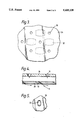
- FIG. 3 is a view on arrow A of FIG. 2;
- FIG. 4 is a view on an enlarged scale of a portion of the combustor wall shown in FIG. 2;
- FIG. 5 is a view on arrow B of FIG. 4.
- FIG. 6 is a view similar to FIG. 2 showing a modified form of combustor in accordance with the present invention.
- a ducted fan gas turbine engine generally indicated at 10 comprises, in axial flow series, an air intake 11, a propulsive fan 12, an intermediate pressure compressor 13, a high pressure compressor 14, combustion equipment 15, a high pressure turbine 16, an intermediate pressure turbine 17, a low pressure turbine 18 and an exhaust nozzle 19.
- the gas turbine engine 10 works in the conventional manner so that air entering the intake 11 is accelerated by the fan 12 to produce two air flows: a first air flow into the intermediate pressure compressor 13 and a second airflow which provides propulsive thrust.
- the intermediate pressure compressor 13 compresses the air flow directed into it before delivering that air to the high pressure compressor 14 where further compression takes place.
- the compressed air exhausted from the high pressure compressor 14 is directed into the combustion equipment 15 where it is mixed with fuel and the mixture combusted.
- the resultant hot combustion products then expand through, and thereby drive, the high, intermediate and low pressure turbines 16,17 and 18 before being exhausted through the nozzle 19 to provide additional propulsive thrust.
- the high, intermediate and low pressure turbines 16,17 and 18 respectively drive the high and intermediate pressure compressors 14 and 13 and the fan 12 by suitable interconnecting shafts.
- the combustion equipment 15 is constituted by an annular combustor 20 having radially inner and outer wall structures 21 and 22 respectively. Fuel is directed into the combustor 20 through a number of fuel nozzles (not shown) located at the upstream end 23 of the combustor 20. The fuel nozzles are circumferentially spaced around the engine 10 and serve to spray fuel into air derived from the high pressure compressor 14. The resultant fuel/air mixture is them combusted within the combustor 20.
- the radially outer wall structure 22 can be seen more clearly if reference is now made to FIG. 2. It will be appreciated, however, that the radially inner wall structure 21 is of the same general configuration as the radially outer wall structure 22.
- the radially outer wall structure 22 comprises an outer wall 24 and an inner wall 25.
- the inner wall 25 is made up of a plurality of discreet wall elements 26 which are all of the same general rectangular configuration and are positioned adjacent each other. The majority of each wall element 26 is arranged to be equi-distant from the outer wall 24. However, the periphery of each wall element 26 is provided with a continuous flange 27 to facilitate the spacing apart of the wall element 26 and the outer wall 24. It will be seen therefore that a chamber 28 is thereby defined between each wall element 26 and the outer wall 24.
- Each wall element 26 is of cast construction and is provided with integral bolts 29 which facilitate its attachment to the outer wall 24.
- the angled effusion holes 32 which can be seen more clearly in FIGS. 4 and 5, are not of circular cross-sectional shape. Instead they are all of the so-called race-track configuration, that is, they have two parallel sides interconnected by semi-circular cross-section portions. This shape, together with the inclination of the hole 32, ensures that air exhausted from them forms a film of cooling air over the inward surface of each wall element 26, that is, the surface which confronts the combustion process which takes place within the combustor 20. This film of cooling air assists in protecting the wall elements 26 from the effects of the high temperature gases within the combustor 20.
- each of the wall elements 26 is provided with two highly effective forms of cooling: impingement cooling and film cooling. They are therefore fully protected from the effects of the high temperatures within the combustor 20.
- a further feature of the present invention is that none of the wall elements 26 presents exposed edges to the combustion process within the combustor 20. Consequently the overheating problems which may be experienced with wall elements having such exposed edges are avoided.
- pedestals 33 are integral with the wall elements 26 and engage or terminate very close to the outer wall 24.
- the provision of the pedestals 33, which tend to be located in the central region of each wall element 26, results in a reduction in the number of the angled effusion holes 32 in each wall element 26. Consequently, the angled effusion holes 32 tend to be concentrated in the edge regions of the wall elements 26.
Landscapes
- Engineering & Computer Science (AREA)
- Chemical & Material Sciences (AREA)
- Combustion & Propulsion (AREA)
- Mechanical Engineering (AREA)
- General Engineering & Computer Science (AREA)
- Turbine Rotor Nozzle Sealing (AREA)
Abstract
A gas turbine engine combustor 20 has a wall structure 22 including an outer wall 24 having a plurality of wall elements 26 attached thereto. Each wall element 26 has a flange 27 around its periphery which defines a chamber 28 between each wall element and the outer wall 24. Holes 30 in the outer wall 24 permit the flow of cooing air into each chamber 28 to provide impingement cooling of the wall elements 26. Holes 30 in the wall elements 26 permit the exhaustion of cooling air from the chambers to provide film cooling of the wall elements 26.
Description
This is a continuation of application Ser. No. 119,141, filed as PCT/GB92/00201, Feb. 3, 1992, which was abandoned upon the filing hereof.
This invention relates to a gas turbine engine combustor and in particular to the construction of the wall of such a combustor.
The combustion process which takes place within the combustor of a gas turbine engine results in the combustor walls being exposed to extremely high temperatures. The alloys used in combustor wall construction are normally unable to withstand these temperatures without some form of cooling. Various combustor wall designs have been employed in the past which make use of pressurised air derived from the engine compressor for cooling purposes. In one particular wall design described in Great Britain Patent Application No 2,087,065A, the wall is made up of two parts: a continuous outer wall and an inner wall made up of a number of partially overlapping inner wall elements. The outer wall and inner wall elements are maintained in spaced apart relationship and cooling air is directed through holes in the outer wall into the space defined between them.. The cooling air flows through the space to be exhausted through gaps defined between the overlapping portions of the inner wall elements. The cooling air thereby provides convection cooling as it flows between the inner wall elements and outer wall and film cooling of the inner wall elements after it has been exhausted from the gaps between inner wall elements.
It has been found with combustion chamber walls of this type that the film cooling of the inner wall elements is not as effective as would normally be desired. This can lead to overheating of and possible damage to the exposed edges of the overlapping portions of the inner wall elements.
It is an object of the present invention to provide a gas turbine engine combustor wall construction in which such film cooling is of improved effectiveness.
According to the present invention, a gas turbine engine annular combustor has a radially inner wall structure and a radially outer wall structure, each wall structure comprising a radially outer wall and a radially inner wall, said radially inner wall being constituted by a plurality of discreet wall elements, means being provided to maintain said wall elements and said radially outer wall in spaced apart relationship, said radially outer wall being apertured to permit the flow of cooling fluid into the spaces defined between said radially outer wall and said wall elements, each of said wall elements being apertured to facilitate the exhaustion of said cooling fluid from said spaces, means being provided to interconnect the periphery of each wall element and said outer wall said interconnection means defining a continuous wall around each wall element periphery which is integral with that periphery so that a discreet chamber is thereby defined between each of said wall elements and said radially outer wall for the flow therethrough of said cooling fluid.
The present invention will now be described, by way of example, with reference to the accompanying drawings:
FIG. 1 is a sectional side view of the upper half of a ducted fan gas turbine engine which incorporates a combustor in accordance with the present invention;
FIG. 2 is a sectional side view of a portion of the wall of the combustor of the gas turbine engine shown in FIG. 1;
FIG. 3 is a view on arrow A of FIG. 2;
FIG. 4 is a view on an enlarged scale of a portion of the combustor wall shown in FIG. 2;
FIG. 5 is a view on arrow B of FIG. 4.
FIG. 6 is a view similar to FIG. 2 showing a modified form of combustor in accordance with the present invention.
With reference to FIG. 1 a ducted fan gas turbine engine generally indicated at 10 comprises, in axial flow series, an air intake 11, a propulsive fan 12, an intermediate pressure compressor 13, a high pressure compressor 14, combustion equipment 15, a high pressure turbine 16, an intermediate pressure turbine 17, a low pressure turbine 18 and an exhaust nozzle 19.
The gas turbine engine 10 works in the conventional manner so that air entering the intake 11 is accelerated by the fan 12 to produce two air flows: a first air flow into the intermediate pressure compressor 13 and a second airflow which provides propulsive thrust. The intermediate pressure compressor 13 compresses the air flow directed into it before delivering that air to the high pressure compressor 14 where further compression takes place.
The compressed air exhausted from the high pressure compressor 14 is directed into the combustion equipment 15 where it is mixed with fuel and the mixture combusted. The resultant hot combustion products then expand through, and thereby drive, the high, intermediate and low pressure turbines 16,17 and 18 before being exhausted through the nozzle 19 to provide additional propulsive thrust. The high, intermediate and low pressure turbines 16,17 and 18 respectively drive the high and intermediate pressure compressors 14 and 13 and the fan 12 by suitable interconnecting shafts.
The combustion equipment 15 is constituted by an annular combustor 20 having radially inner and outer wall structures 21 and 22 respectively. Fuel is directed into the combustor 20 through a number of fuel nozzles (not shown) located at the upstream end 23 of the combustor 20. The fuel nozzles are circumferentially spaced around the engine 10 and serve to spray fuel into air derived from the high pressure compressor 14. The resultant fuel/air mixture is them combusted within the combustor 20.
The combustion process which takes place within the combustion 20 naturally generates a large amount of heat. It is necessary therefore to arrange that the inner and outer wall structures 21 and 22 are capable of withstanding this heat while functioning in a normal manner.
The radially outer wall structure 22 can be seen more clearly if reference is now made to FIG. 2. It will be appreciated, however, that the radially inner wall structure 21 is of the same general configuration as the radially outer wall structure 22.
Referring to FIG. 2, the radially outer wall structure 22 comprises an outer wall 24 and an inner wall 25. The inner wall 25 is made up of a plurality of discreet wall elements 26 which are all of the same general rectangular configuration and are positioned adjacent each other. The majority of each wall element 26 is arranged to be equi-distant from the outer wall 24. However, the periphery of each wall element 26 is provided with a continuous flange 27 to facilitate the spacing apart of the wall element 26 and the outer wall 24. It will be seen therefore that a chamber 28 is thereby defined between each wall element 26 and the outer wall 24.
Each wall element 26 is of cast construction and is provided with integral bolts 29 which facilitate its attachment to the outer wall 24.
During engine operation, some of the air exhausted from the high pressure compressor 14 is permitted to flow over the exterior surfaces of the combustor 20. The air provides combustor 20 cooling and some of it is directed into the interior of the combustor 20 to assist in the combustion process. A large number of holes 30 are provided in the outer wall 24, which can also be seen in FIG. 3, to permit the flow of some of this air into the chambers 28. The air passing through the holes 30 impinges upon the radially outward surfaces of the wall elements 26 as indicated by the air flow indicating arrows 31. This ensures that each of the wall elements 26 is cooled in a highly effective manner. That air is then exhausted from the chambers 28 through a plurality of angled effusion holes 32 provided in each wall element 26. The effusion holes 32 are are so angled as to be aligned in a generally downstream direction with regard to the general fluid flow through the combustor 20.
The angled effusion holes 32, which can be seen more clearly in FIGS. 4 and 5, are not of circular cross-sectional shape. Instead they are all of the so-called race-track configuration, that is, they have two parallel sides interconnected by semi-circular cross-section portions. This shape, together with the inclination of the hole 32, ensures that air exhausted from them forms a film of cooling air over the inward surface of each wall element 26, that is, the surface which confronts the combustion process which takes place within the combustor 20. This film of cooling air assists in protecting the wall elements 26 from the effects of the high temperature gases within the combustor 20.
It will be appreciated that although the present invention has been described with reference to effusion holes 32 which are of race-track cross-sectional configuration, other alternative configurations may also be effective in providing satisfactory wall element 26 cooling.
It will be seen therefore that each of the wall elements 26 is provided with two highly effective forms of cooling: impingement cooling and film cooling. They are therefore fully protected from the effects of the high temperatures within the combustor 20.
A further feature of the present invention is that none of the wall elements 26 presents exposed edges to the combustion process within the combustor 20. Consequently the overheating problems which may be experienced with wall elements having such exposed edges are avoided.
It may be desirable in certain circumstances to enhance the heat exchange relationship between the cooling air passing through the chambers 28 and the wall elements 26. One way of readily achieving this would be to provide pedestals 33 or other suitable devices to increase surface area on the surfaces of the wall elements 26 which confront the outer wall 24 as can be seen in FIG. 6. The pedestals 33 are integral with the wall elements 26 and engage or terminate very close to the outer wall 24. The provision of the pedestals 33, which tend to be located in the central region of each wall element 26, results in a reduction in the number of the angled effusion holes 32 in each wall element 26. Consequently, the angled effusion holes 32 tend to be concentrated in the edge regions of the wall elements 26.
Claims (9)
1. A gas turbine engine annular combustor having an inner wall structure and an outer wall structure, each of said wall structures comprising an outer wall and an inner wall, said inner wall comprising a plurality or discreet wall elements covering at least portions of said inner wall, said discreet wall elements cooperating with removable bolts provided to removably maintain a majority of said wall elements and said outer wall in spaced apart relationship, each wall element being formed from a single piece of material and having a main portion and a periphery extending from said main portion, said periphery being in engagement with said outer wall to define with said outer wall a discreet chamber for the flow therethrough of a cooling fluid, said outer wall being apertured to permit the flow of a cooling fluid into the discreet chambers defined between said outer wall and said wall elements, each of said wall elements being apertured to facilitate the exhaustion of the cooling fluid from said chambers.
2. A gas turbine engine combustor as claimed in claim 1 characterised in that said apertures (30) in said outer wall (24) are so arranged as to direct cooling fluid on to said wall elements (26) to provide impingement cooling thereof.
3. A gas turbine engine combustor as claimed in claim 1 or claim 2 characterised in that said apertures (32) in each of said wall elements (25) are so arranged as to exhaust cooling fluid from said discreet chambers (28) to provide film cooling of said wall elements (25).
4. A gas turbine engine combustor as claimed in claim 3 wherein said combustor is arranged to have a general direction of fluid flow therethrough and said apertures in said wall elements are inclined in said general direction of fluid flow to facilitate said film cooling of said wall elements.
5. A gas turbine engine combustor as claimed in claim 4 characterised in that said apertures (32) in said wall elements (25) are of race-track cross-sectional configuration.
6. A gas turbine engine combustor as claimed in claim 1 characterised in that said wall elements (25) are positioned on said outer wall (24) so as to be generally adjacent each other.
7. A gas turbine engine combustor as claimed in claim 1 characterised in that each of said wall elements (25) is provided with integral bolts (29) to facilitate its attachment to said outer wall (24).
8. A gas turbine engine combustor as claimed in claim 1 characterised in that each of said wall elements (25) is provided with a plurality of pedestals (33) to enhance the heat exchange relationship between said wall elements (25) and said cooling fluid flow through said spaces (28) between said wall elements (25) and said outer wall (24).
9. A gas turbine engine combustor as claimed in claim 8 characterised in that each of said pedestals (33) engages said outer wall (24).
Priority Applications (1)
| Application Number | Priority Date | Filing Date | Title |
|---|---|---|---|
| US08/369,297 US5435139A (en) | 1991-03-22 | 1995-01-06 | Removable combustor liner for gas turbine engine combustor |
Applications Claiming Priority (4)
| Application Number | Priority Date | Filing Date | Title |
|---|---|---|---|
| GB919106085A GB9106085D0 (en) | 1991-03-22 | 1991-03-22 | Gas turbine engine combustor |
| GB9106085 | 1991-03-22 | ||
| US11914193A | 1993-09-20 | 1993-09-20 | |
| US08/369,297 US5435139A (en) | 1991-03-22 | 1995-01-06 | Removable combustor liner for gas turbine engine combustor |
Related Parent Applications (1)
| Application Number | Title | Priority Date | Filing Date |
|---|---|---|---|
| US11914193A Continuation | 1991-03-22 | 1993-09-20 |
Publications (1)
| Publication Number | Publication Date |
|---|---|
| US5435139A true US5435139A (en) | 1995-07-25 |
Family
ID=26298620
Family Applications (1)
| Application Number | Title | Priority Date | Filing Date |
|---|---|---|---|
| US08/369,297 Expired - Lifetime US5435139A (en) | 1991-03-22 | 1995-01-06 | Removable combustor liner for gas turbine engine combustor |
Country Status (1)
| Country | Link |
|---|---|
| US (1) | US5435139A (en) |
Cited By (89)
| Publication number | Priority date | Publication date | Assignee | Title |
|---|---|---|---|---|
| US5560197A (en) * | 1993-12-22 | 1996-10-01 | Societe Nationale D'etude Et De Construction De Moteurs D'aviation "Snecma" | Fixing arrangement for a thermal protection tile in a combustion chamber |
| US5647202A (en) * | 1994-12-09 | 1997-07-15 | Asea Brown Boveri Ag | Cooled wall part |
| US5651662A (en) * | 1992-10-29 | 1997-07-29 | General Electric Company | Film cooled wall |
| US5758503A (en) * | 1995-05-03 | 1998-06-02 | United Technologies Corporation | Gas turbine combustor |
| US5758504A (en) * | 1996-08-05 | 1998-06-02 | Solar Turbines Incorporated | Impingement/effusion cooled combustor liner |
| US5782294A (en) * | 1995-12-18 | 1998-07-21 | United Technologies Corporation | Cooled liner apparatus |
| US5829341A (en) * | 1998-03-24 | 1998-11-03 | Lin; Jenny | Automatic cooker having a card-type controller for controlling cooking conditions according to cooking data stored in a removable control card |
| US6041590A (en) * | 1996-11-13 | 2000-03-28 | Rolls-Royce, Plc | Jet pipe liner |
| US6079199A (en) * | 1998-06-03 | 2000-06-27 | Pratt & Whitney Canada Inc. | Double pass air impingement and air film cooling for gas turbine combustor walls |
| US6497105B1 (en) | 2001-06-04 | 2002-12-24 | Pratt & Whitney Canada Corp. | Low cost combustor burner collar |
| US6546731B2 (en) | 1999-12-01 | 2003-04-15 | Abb Alstom Power Uk Ltd. | Combustion chamber for a gas turbine engine |
| DE10154285A1 (en) * | 2001-11-05 | 2003-05-15 | Rolls Royce Deutschland | Heat shield device with plates fixed to wall by bolt through wall has collar-form recess in edge region |
| EP1351021A2 (en) | 2002-04-02 | 2003-10-08 | Rolls-Royce Deutschland Ltd & Co KG | Turbine combustor with starting film cooling |
| RU2215241C2 (en) * | 2002-01-23 | 2003-10-27 | Открытое акционерное общество "Авиадвигатель" | Gas-turbine engine combustion chamber |
| US20030213250A1 (en) * | 2002-05-16 | 2003-11-20 | Monica Pacheco-Tougas | Heat shield panels for use in a combustor for a gas turbine engine |
| US6701714B2 (en) * | 2001-12-05 | 2004-03-09 | United Technologies Corporation | Gas turbine combustor |
| US20040045298A1 (en) * | 2001-03-12 | 2004-03-11 | Rolls-Royce Plc | Combustion apparatus |
| US6711900B1 (en) * | 2003-02-04 | 2004-03-30 | Pratt & Whitney Canada Corp. | Combustor liner V-band design |
| US20040211188A1 (en) * | 2003-04-28 | 2004-10-28 | Hisham Alkabie | Noise reducing combustor |
| US20040255597A1 (en) * | 2003-05-12 | 2004-12-23 | Siemens Westinghouse Power Corporation | Attachment system for coupling combustor liners to a carrier of a turbine combustor |
| EP1503144A1 (en) * | 2003-07-31 | 2005-02-02 | United Technologies Corporation | Combustor |
| US20050044856A1 (en) * | 2003-08-28 | 2005-03-03 | Siemens Westinghouse Power Corporation | Turbine component with enhanced stagnation prevention and corner heat distribution |
| US20050086940A1 (en) * | 2003-10-23 | 2005-04-28 | Coughlan Joseph D.Iii | Combustor |
| US20050097890A1 (en) * | 2003-08-29 | 2005-05-12 | Mitsubishi Heavy Industries, Ltd. | Gas turbine combustor |
| US20050097891A1 (en) * | 2003-09-04 | 2005-05-12 | Karl Schreiber | Arrangement for the cooling of thermally highly loaded components |
| US20050188678A1 (en) * | 2001-12-18 | 2005-09-01 | Volvo Aero Corporation | Component for being subjected to high thermal load during operation and a method for manufacturing such a component |
| US20060005543A1 (en) * | 2004-07-12 | 2006-01-12 | Burd Steven W | Heatshielded article |
| US20060037322A1 (en) * | 2003-10-09 | 2006-02-23 | Burd Steven W | Gas turbine annular combustor having a first converging volume and a second converging volume, converging less gradually than the first converging volume |
| US20060042268A1 (en) * | 2004-08-24 | 2006-03-02 | Pratt & Whitney Canada Corp. | Gas turbine floating collar arrangement |
| US20060042269A1 (en) * | 2004-08-24 | 2006-03-02 | Pratt & Whitney Canada Corp. | Gas turbine floating collar |
| US20060053798A1 (en) * | 2004-09-10 | 2006-03-16 | Honeywell International Inc. | Waffled impingement effusion method |
| US20060059916A1 (en) * | 2004-09-09 | 2006-03-23 | Cheung Albert K | Cooled turbine engine components |
| FR2889732A1 (en) * | 2005-08-12 | 2007-02-16 | Snecma | Combustion chamber for turbomachine, has annular inner and outer walls including perforations emerging relative to tabs and constituted of holes whose axis forms, with longitudinal axis, angle comprised between preset values |
| US20070125093A1 (en) * | 2005-12-06 | 2007-06-07 | United Technologies Corporation | Gas turbine combustor |
| US20070144177A1 (en) * | 2005-12-22 | 2007-06-28 | Burd Steven W | Combustor turbine interface |
| US20070209366A1 (en) * | 2006-03-10 | 2007-09-13 | Miklos Gerendas | Gas turbine combustion chamber wall with dampening effect on combustion chamber vibrations |
| US20070245742A1 (en) * | 2004-10-25 | 2007-10-25 | Stefan Dahlke | Method of Optimum Controlled Outlet, Impingement Cooling and Sealing of a Heat Shield and a Heat Shield Element |
| US20070271925A1 (en) * | 2006-05-26 | 2007-11-29 | Pratt & Whitney Canada Corp. | Combustor with improved swirl |
| US20070271926A1 (en) * | 2006-05-26 | 2007-11-29 | Pratt & Whitney Canada Corp. | Noise reducing combustor |
| US20070283700A1 (en) * | 2006-06-09 | 2007-12-13 | Miklos Gerendas | Gas-turbine combustion chamber wall for a lean-burning gas-turbine combustion chamber |
| US20080282703A1 (en) * | 2007-05-16 | 2008-11-20 | Oleg Morenko | Interface between a combustor and fuel nozzle |
| US20080292457A1 (en) * | 2004-01-09 | 2008-11-27 | Mtu Aero Engines Gmbh | Device for Suspending Guide Blades |
| EP1998115A1 (en) * | 2007-05-29 | 2008-12-03 | Siemens Aktiengesellschaft | Cooling channel for cooling a component carrying a hot gas |
| US20090077974A1 (en) * | 2003-08-13 | 2009-03-26 | Stefan Dahlke | Heat Shield Arrangement for a Component Guiding a Hot Gas in Particular for a Combustion Chamber in a Gas Turbine |
| EP2071240A1 (en) * | 2007-12-14 | 2009-06-17 | Snecma | Turboengine combustion chamber |
| US20090151360A1 (en) * | 2007-12-18 | 2009-06-18 | United Technologies Corporation | Combustor |
| JP2010091258A (en) * | 2008-10-03 | 2010-04-22 | General Electric Co <Ge> | Premixed direct injection nozzle |
| US20100095680A1 (en) * | 2008-10-22 | 2010-04-22 | Honeywell International Inc. | Dual wall structure for use in a combustor of a gas turbine engine |
| US20100095678A1 (en) * | 2008-10-22 | 2010-04-22 | Eduardo Hawie | Heat Shield Sealing for Gas Turbine Engine Combustor |
| US20100095679A1 (en) * | 2008-10-22 | 2010-04-22 | Honeywell International Inc. | Dual wall structure for use in a combustor of a gas turbine engine |
| US20100242483A1 (en) * | 2009-03-30 | 2010-09-30 | United Technologies Corporation | Combustor for gas turbine engine |
| US20100263386A1 (en) * | 2009-04-16 | 2010-10-21 | General Electric Company | Turbine engine having a liner |
| US20100272953A1 (en) * | 2009-04-28 | 2010-10-28 | Honeywell International Inc. | Cooled hybrid structure for gas turbine engine and method for the fabrication thereof |
| EP2275743A2 (en) | 2009-07-17 | 2011-01-19 | Rolls-Royce Deutschland Ltd & Co KG | Gas turbine combustion chamber with starter film for cooling the combustion chamber wall |
| US20110011095A1 (en) * | 2009-07-17 | 2011-01-20 | Ladd Scott A | Washer with cooling passage for a turbine engine combustor |
| US20110048024A1 (en) * | 2009-08-31 | 2011-03-03 | United Technologies Corporation | Gas turbine combustor with quench wake control |
| US20110126543A1 (en) * | 2009-11-30 | 2011-06-02 | United Technologies Corporation | Combustor panel arrangement |
| US20110185735A1 (en) * | 2010-01-29 | 2011-08-04 | United Technologies Corporation | Gas turbine combustor with staged combustion |
| US20120047908A1 (en) * | 2010-08-27 | 2012-03-01 | Alstom Technology Ltd | Method for operating a burner arrangement and burner arrangement for implementing the method |
| EP2505787A1 (en) * | 2011-03-28 | 2012-10-03 | Rolls-Royce plc | Component of a gas turbine engine and corresponding gas turbine engine |
| US20120255308A1 (en) * | 2011-04-06 | 2012-10-11 | Rolls-Royce Plc | Cooled double walled article |
| US20130019603A1 (en) * | 2011-07-21 | 2013-01-24 | Dierberger James A | Insert for gas turbine engine combustor |
| US8443610B2 (en) | 2009-11-25 | 2013-05-21 | United Technologies Corporation | Low emission gas turbine combustor |
| US8479521B2 (en) | 2011-01-24 | 2013-07-09 | United Technologies Corporation | Gas turbine combustor with liner air admission holes associated with interspersed main and pilot swirler assemblies |
| WO2014018963A1 (en) * | 2012-07-27 | 2014-01-30 | United Technologies Corporation | Turbine engine combustor and stator vane assembly |
| US8667682B2 (en) | 2011-04-27 | 2014-03-11 | Siemens Energy, Inc. | Method of fabricating a nearwall nozzle impingement cooled component for an internal combustion engine |
| WO2014052966A1 (en) | 2012-09-28 | 2014-04-03 | United Technologies Corporation | Combustor section of a gas turbine engine |
| EP2743585A1 (en) | 2012-12-12 | 2014-06-18 | Rolls-Royce plc | A combustion chamber |
| US8966877B2 (en) | 2010-01-29 | 2015-03-03 | United Technologies Corporation | Gas turbine combustor with variable airflow |
| WO2015077755A1 (en) * | 2013-11-25 | 2015-05-28 | United Technologies Corporation | Film cooled multi-walled structure with one or more indentations |
| US9068748B2 (en) | 2011-01-24 | 2015-06-30 | United Technologies Corporation | Axial stage combustor for gas turbine engines |
| EP2918914A1 (en) | 2014-03-11 | 2015-09-16 | Rolls-Royce Deutschland Ltd & Co KG | Combustion chamber of a gas turbine |
| EP2918913A1 (en) | 2014-03-11 | 2015-09-16 | Rolls-Royce Deutschland Ltd & Co KG | Combustion chamber of a gas turbine |
| US20160298841A1 (en) * | 2015-04-13 | 2016-10-13 | Pratt & Whitney Canada Corp. | Combustor heat shield |
| US20160305663A1 (en) * | 2015-04-17 | 2016-10-20 | Pratt & Whitney Canada Corp. | Gas turbine engine combustor |
| US9494081B2 (en) | 2013-05-09 | 2016-11-15 | Siemens Aktiengesellschaft | Turbine engine shutdown temperature control system with an elongated ejector |
| US9498848B2 (en) | 2013-01-30 | 2016-11-22 | Rolls-Royce Plc | Method of manufacturing a wall |
| US20170003026A1 (en) * | 2015-06-30 | 2017-01-05 | Rolls-Royce Corporation | Combustor tile |
| US20170108219A1 (en) * | 2015-10-16 | 2017-04-20 | Rolls-Royce Plc | Combustor for a gas turbine engine |
| US20170159936A1 (en) * | 2013-12-31 | 2017-06-08 | United Technologies Corporation | Gas turbine engine wall assembly with enhanced flow architecture |
| US20170241643A1 (en) * | 2016-02-24 | 2017-08-24 | Rolls-Royce Plc | Combustion chamber |
| US20170363296A1 (en) * | 2016-06-17 | 2017-12-21 | Pratt & Whitney Canada Corp. | Small exit duct for a reverse flow combustor with integrated fastening elements |
| US9958162B2 (en) | 2011-01-24 | 2018-05-01 | United Technologies Corporation | Combustor assembly for a turbine engine |
| US9970660B2 (en) | 2014-07-25 | 2018-05-15 | Rolls-Royce Plc | Liner element for a combustor |
| US10451277B2 (en) | 2014-10-13 | 2019-10-22 | Rolls-Royce Plc | Liner element for a combustor, and a related method |
| US10670269B2 (en) * | 2016-10-26 | 2020-06-02 | Raytheon Technologies Corporation | Cast combustor liner panel gating feature for a gas turbine engine combustor |
| US10753611B2 (en) | 2016-11-21 | 2020-08-25 | General Electric Corporation Gmbh | System and method for impingement cooling of turbine system components |
| US10823410B2 (en) * | 2016-10-26 | 2020-11-03 | Raytheon Technologies Corporation | Cast combustor liner panel radius for gas turbine engine combustor |
| US20230129962A1 (en) * | 2021-10-21 | 2023-04-27 | Raytheon Technologies Corporation | Tongue joint including mating channel for cooling |
Citations (18)
| Publication number | Priority date | Publication date | Assignee | Title |
|---|---|---|---|---|
| GB1093515A (en) * | 1966-04-06 | 1967-12-06 | Rolls Royce | Method of producing combustion chambers and similar components for gas turbine engines |
| US3422620A (en) * | 1967-05-04 | 1969-01-21 | Westinghouse Electric Corp | Combustion apparatus |
| FR2333126A1 (en) * | 1975-11-29 | 1977-06-24 | Rolls Royce | GAS TURBINE ENGINE COMBUSTION CHAMBER REFRIGERATION DEVICE |
| US4071194A (en) * | 1976-10-28 | 1978-01-31 | The United States Of America As Represented By The Secretary Of The Navy | Means for cooling exhaust nozzle sidewalls |
| GB2073399A (en) * | 1980-04-02 | 1981-10-14 | United Technologies Corp | Dual premix tube fuel nozzle |
| GB2087065A (en) * | 1980-11-08 | 1982-05-19 | Rolls Royce | Wall structure for a combustion chamber |
| JPS5872822A (en) * | 1981-10-26 | 1983-04-30 | Hitachi Ltd | Gas turbine combustor cooling structure |
| JPS58182034A (en) * | 1982-04-19 | 1983-10-24 | Hitachi Ltd | Gas turbine combustor tail cylinder |
| US4422300A (en) * | 1981-12-14 | 1983-12-27 | United Technologies Corporation | Prestressed combustor liner for gas turbine engine |
| US4695247A (en) * | 1985-04-05 | 1987-09-22 | Director-General Of The Agency Of Industrial Science & Technology | Combustor of gas turbine |
| EP0239020A2 (en) * | 1986-03-20 | 1987-09-30 | Hitachi, Ltd. | Gas turbine combustion apparatus |
| EP0269824A2 (en) * | 1986-11-25 | 1988-06-08 | General Electric Company | Premixed pilot nozzle for dry low NOx combustor |
| GB2204672A (en) * | 1987-05-06 | 1988-11-16 | Rolls Royce Plc | Combustor |
| US4901522A (en) * | 1987-12-16 | 1990-02-20 | Societe Nationale D'etude Et De Construction De Moteurs D'aviation (Snecma) | Turbojet engine combustion chamber with a double wall converging zone |
| FR2635577A1 (en) * | 1988-08-17 | 1990-02-23 | Rolls Royce Plc | COMBUSTION CHAMBER FOR GAS TURBINE ENGINE |
| US4912922A (en) * | 1972-12-19 | 1990-04-03 | General Electric Company | Combustion chamber construction |
| EP0488766A1 (en) * | 1990-11-30 | 1992-06-03 | Hitachi, Ltd. | Method and device for controlling combustors for gas-turbine |
| US5216886A (en) * | 1991-08-14 | 1993-06-08 | The United States Of America As Represented By The Secretary Of The Air Force | Segmented cell wall liner for a combustion chamber |
-
1995
- 1995-01-06 US US08/369,297 patent/US5435139A/en not_active Expired - Lifetime
Patent Citations (20)
| Publication number | Priority date | Publication date | Assignee | Title |
|---|---|---|---|---|
| GB1093515A (en) * | 1966-04-06 | 1967-12-06 | Rolls Royce | Method of producing combustion chambers and similar components for gas turbine engines |
| US3422620A (en) * | 1967-05-04 | 1969-01-21 | Westinghouse Electric Corp | Combustion apparatus |
| US4912922A (en) * | 1972-12-19 | 1990-04-03 | General Electric Company | Combustion chamber construction |
| FR2333126A1 (en) * | 1975-11-29 | 1977-06-24 | Rolls Royce | GAS TURBINE ENGINE COMBUSTION CHAMBER REFRIGERATION DEVICE |
| US4071194A (en) * | 1976-10-28 | 1978-01-31 | The United States Of America As Represented By The Secretary Of The Navy | Means for cooling exhaust nozzle sidewalls |
| GB2073399A (en) * | 1980-04-02 | 1981-10-14 | United Technologies Corp | Dual premix tube fuel nozzle |
| GB2087065A (en) * | 1980-11-08 | 1982-05-19 | Rolls Royce | Wall structure for a combustion chamber |
| JPS5872822A (en) * | 1981-10-26 | 1983-04-30 | Hitachi Ltd | Gas turbine combustor cooling structure |
| US4422300A (en) * | 1981-12-14 | 1983-12-27 | United Technologies Corporation | Prestressed combustor liner for gas turbine engine |
| JPS58182034A (en) * | 1982-04-19 | 1983-10-24 | Hitachi Ltd | Gas turbine combustor tail cylinder |
| US4695247A (en) * | 1985-04-05 | 1987-09-22 | Director-General Of The Agency Of Industrial Science & Technology | Combustor of gas turbine |
| EP0239020A2 (en) * | 1986-03-20 | 1987-09-30 | Hitachi, Ltd. | Gas turbine combustion apparatus |
| EP0269824A2 (en) * | 1986-11-25 | 1988-06-08 | General Electric Company | Premixed pilot nozzle for dry low NOx combustor |
| GB2204672A (en) * | 1987-05-06 | 1988-11-16 | Rolls Royce Plc | Combustor |
| US4864827A (en) * | 1987-05-06 | 1989-09-12 | Rolls-Royce Plc | Combustor |
| US4901522A (en) * | 1987-12-16 | 1990-02-20 | Societe Nationale D'etude Et De Construction De Moteurs D'aviation (Snecma) | Turbojet engine combustion chamber with a double wall converging zone |
| FR2635577A1 (en) * | 1988-08-17 | 1990-02-23 | Rolls Royce Plc | COMBUSTION CHAMBER FOR GAS TURBINE ENGINE |
| US5000005A (en) * | 1988-08-17 | 1991-03-19 | Rolls-Royce, Plc | Combustion chamber for a gas turbine engine |
| EP0488766A1 (en) * | 1990-11-30 | 1992-06-03 | Hitachi, Ltd. | Method and device for controlling combustors for gas-turbine |
| US5216886A (en) * | 1991-08-14 | 1993-06-08 | The United States Of America As Represented By The Secretary Of The Air Force | Segmented cell wall liner for a combustion chamber |
Cited By (164)
| Publication number | Priority date | Publication date | Assignee | Title |
|---|---|---|---|---|
| US5651662A (en) * | 1992-10-29 | 1997-07-29 | General Electric Company | Film cooled wall |
| US5560197A (en) * | 1993-12-22 | 1996-10-01 | Societe Nationale D'etude Et De Construction De Moteurs D'aviation "Snecma" | Fixing arrangement for a thermal protection tile in a combustion chamber |
| US5647202A (en) * | 1994-12-09 | 1997-07-15 | Asea Brown Boveri Ag | Cooled wall part |
| US5758503A (en) * | 1995-05-03 | 1998-06-02 | United Technologies Corporation | Gas turbine combustor |
| US5782294A (en) * | 1995-12-18 | 1998-07-21 | United Technologies Corporation | Cooled liner apparatus |
| US5758504A (en) * | 1996-08-05 | 1998-06-02 | Solar Turbines Incorporated | Impingement/effusion cooled combustor liner |
| US6041590A (en) * | 1996-11-13 | 2000-03-28 | Rolls-Royce, Plc | Jet pipe liner |
| US5829341A (en) * | 1998-03-24 | 1998-11-03 | Lin; Jenny | Automatic cooker having a card-type controller for controlling cooking conditions according to cooking data stored in a removable control card |
| US6079199A (en) * | 1998-06-03 | 2000-06-27 | Pratt & Whitney Canada Inc. | Double pass air impingement and air film cooling for gas turbine combustor walls |
| US6546731B2 (en) | 1999-12-01 | 2003-04-15 | Abb Alstom Power Uk Ltd. | Combustion chamber for a gas turbine engine |
| US20040083739A1 (en) * | 2001-03-12 | 2004-05-06 | Rolls-Royce Plc | Combustion apparatus |
| GB2373319B (en) * | 2001-03-12 | 2005-03-30 | Rolls Royce Plc | Combustion apparatus |
| US6857275B2 (en) * | 2001-03-12 | 2005-02-22 | Rolls-Royce Plc | Combustion apparatus |
| US20040045298A1 (en) * | 2001-03-12 | 2004-03-11 | Rolls-Royce Plc | Combustion apparatus |
| US6708499B2 (en) * | 2001-03-12 | 2004-03-23 | Rolls-Royce Plc | Combustion apparatus |
| US6497105B1 (en) | 2001-06-04 | 2002-12-24 | Pratt & Whitney Canada Corp. | Low cost combustor burner collar |
| DE10154285A1 (en) * | 2001-11-05 | 2003-05-15 | Rolls Royce Deutschland | Heat shield device with plates fixed to wall by bolt through wall has collar-form recess in edge region |
| US6701714B2 (en) * | 2001-12-05 | 2004-03-09 | United Technologies Corporation | Gas turbine combustor |
| US7299622B2 (en) * | 2001-12-18 | 2007-11-27 | Volvo Aero Corporation | Component for being subjected to high thermal load during operation and a method for manufacturing such a component |
| US20050188678A1 (en) * | 2001-12-18 | 2005-09-01 | Volvo Aero Corporation | Component for being subjected to high thermal load during operation and a method for manufacturing such a component |
| RU2215241C2 (en) * | 2002-01-23 | 2003-10-27 | Открытое акционерное общество "Авиадвигатель" | Gas-turbine engine combustion chamber |
| EP1351021A2 (en) | 2002-04-02 | 2003-10-08 | Rolls-Royce Deutschland Ltd & Co KG | Turbine combustor with starting film cooling |
| EP2322857A1 (en) * | 2002-05-16 | 2011-05-18 | United Technologies Corporation | Heat shield panels |
| US7093439B2 (en) * | 2002-05-16 | 2006-08-22 | United Technologies Corporation | Heat shield panels for use in a combustor for a gas turbine engine |
| EP1363075A3 (en) * | 2002-05-16 | 2005-07-13 | United Technologies Corporation | Heat shield panels for use in a combustor for a gas turbine engine |
| US20030213250A1 (en) * | 2002-05-16 | 2003-11-20 | Monica Pacheco-Tougas | Heat shield panels for use in a combustor for a gas turbine engine |
| US6711900B1 (en) * | 2003-02-04 | 2004-03-30 | Pratt & Whitney Canada Corp. | Combustor liner V-band design |
| US20040159106A1 (en) * | 2003-02-04 | 2004-08-19 | Patel Bhawan Bhal | Combustor liner V-band design |
| WO2004070275A1 (en) * | 2003-02-04 | 2004-08-19 | Pratt & Whitney Canada Corp. | Combustor liner v-band louver |
| US20040211188A1 (en) * | 2003-04-28 | 2004-10-28 | Hisham Alkabie | Noise reducing combustor |
| US6964170B2 (en) | 2003-04-28 | 2005-11-15 | Pratt & Whitney Canada Corp. | Noise reducing combustor |
| US20040255597A1 (en) * | 2003-05-12 | 2004-12-23 | Siemens Westinghouse Power Corporation | Attachment system for coupling combustor liners to a carrier of a turbine combustor |
| US6931855B2 (en) * | 2003-05-12 | 2005-08-23 | Siemens Westinghouse Power Corporation | Attachment system for coupling combustor liners to a carrier of a turbine combustor |
| US20050022531A1 (en) * | 2003-07-31 | 2005-02-03 | Burd Steven W. | Combustor |
| US7146815B2 (en) | 2003-07-31 | 2006-12-12 | United Technologies Corporation | Combustor |
| EP1503144A1 (en) * | 2003-07-31 | 2005-02-02 | United Technologies Corporation | Combustor |
| US20090077974A1 (en) * | 2003-08-13 | 2009-03-26 | Stefan Dahlke | Heat Shield Arrangement for a Component Guiding a Hot Gas in Particular for a Combustion Chamber in a Gas Turbine |
| US7849694B2 (en) * | 2003-08-13 | 2010-12-14 | Siemens Aktiengesellschaft | Heat shield arrangement for a component guiding a hot gas in particular for a combustion chamber in a gas turbine |
| US20050044856A1 (en) * | 2003-08-28 | 2005-03-03 | Siemens Westinghouse Power Corporation | Turbine component with enhanced stagnation prevention and corner heat distribution |
| US7104068B2 (en) * | 2003-08-28 | 2006-09-12 | Siemens Power Generation, Inc. | Turbine component with enhanced stagnation prevention and corner heat distribution |
| US7089741B2 (en) * | 2003-08-29 | 2006-08-15 | Mitsubishi Heavy Industries, Ltd. | Gas turbine combustor |
| US20050097890A1 (en) * | 2003-08-29 | 2005-05-12 | Mitsubishi Heavy Industries, Ltd. | Gas turbine combustor |
| US20050097891A1 (en) * | 2003-09-04 | 2005-05-12 | Karl Schreiber | Arrangement for the cooling of thermally highly loaded components |
| US7204089B2 (en) * | 2003-09-04 | 2007-04-17 | Rolls-Royce Deutschland Ltd & Co Kg | Arrangement for the cooling of thermally highly loaded components |
| US20060037322A1 (en) * | 2003-10-09 | 2006-02-23 | Burd Steven W | Gas turbine annular combustor having a first converging volume and a second converging volume, converging less gradually than the first converging volume |
| US7093441B2 (en) | 2003-10-09 | 2006-08-22 | United Technologies Corporation | Gas turbine annular combustor having a first converging volume and a second converging volume, converging less gradually than the first converging volume |
| US20090293488A1 (en) * | 2003-10-23 | 2009-12-03 | United Technologies Corporation | Combustor |
| US8015829B2 (en) | 2003-10-23 | 2011-09-13 | United Technologies Corporation | Combustor |
| US20050086940A1 (en) * | 2003-10-23 | 2005-04-28 | Coughlan Joseph D.Iii | Combustor |
| EP1528322A3 (en) * | 2003-10-23 | 2005-06-08 | United Technologies Corporation | Combustor |
| EP2034244A1 (en) | 2003-10-23 | 2009-03-11 | United Technologies Corporation | Combustor |
| US7363763B2 (en) | 2003-10-23 | 2008-04-29 | United Technologies Corporation | Combustor |
| US8591182B2 (en) * | 2004-01-09 | 2013-11-26 | Mtu Aero Engines Gmbh | Device for suspending guide blades |
| US20080292457A1 (en) * | 2004-01-09 | 2008-11-27 | Mtu Aero Engines Gmbh | Device for Suspending Guide Blades |
| US7140185B2 (en) * | 2004-07-12 | 2006-11-28 | United Technologies Corporation | Heatshielded article |
| US20060005543A1 (en) * | 2004-07-12 | 2006-01-12 | Burd Steven W | Heatshielded article |
| US7134286B2 (en) | 2004-08-24 | 2006-11-14 | Pratt & Whitney Canada Corp. | Gas turbine floating collar arrangement |
| US20070261409A1 (en) * | 2004-08-24 | 2007-11-15 | Lorin Markarian | Gas turbine floating collar |
| US20060042268A1 (en) * | 2004-08-24 | 2006-03-02 | Pratt & Whitney Canada Corp. | Gas turbine floating collar arrangement |
| US8015706B2 (en) | 2004-08-24 | 2011-09-13 | Lorin Markarian | Gas turbine floating collar |
| US7140189B2 (en) | 2004-08-24 | 2006-11-28 | Pratt & Whitney Canada Corp. | Gas turbine floating collar |
| US20060042269A1 (en) * | 2004-08-24 | 2006-03-02 | Pratt & Whitney Canada Corp. | Gas turbine floating collar |
| US20060059916A1 (en) * | 2004-09-09 | 2006-03-23 | Cheung Albert K | Cooled turbine engine components |
| US7464554B2 (en) * | 2004-09-09 | 2008-12-16 | United Technologies Corporation | Gas turbine combustor heat shield panel or exhaust panel including a cooling device |
| US7219498B2 (en) | 2004-09-10 | 2007-05-22 | Honeywell International, Inc. | Waffled impingement effusion method |
| US20060053798A1 (en) * | 2004-09-10 | 2006-03-16 | Honeywell International Inc. | Waffled impingement effusion method |
| US20070245742A1 (en) * | 2004-10-25 | 2007-10-25 | Stefan Dahlke | Method of Optimum Controlled Outlet, Impingement Cooling and Sealing of a Heat Shield and a Heat Shield Element |
| FR2889732A1 (en) * | 2005-08-12 | 2007-02-16 | Snecma | Combustion chamber for turbomachine, has annular inner and outer walls including perforations emerging relative to tabs and constituted of holes whose axis forms, with longitudinal axis, angle comprised between preset values |
| US20070125093A1 (en) * | 2005-12-06 | 2007-06-07 | United Technologies Corporation | Gas turbine combustor |
| US7954325B2 (en) | 2005-12-06 | 2011-06-07 | United Technologies Corporation | Gas turbine combustor |
| US20070144177A1 (en) * | 2005-12-22 | 2007-06-28 | Burd Steven W | Combustor turbine interface |
| US7934382B2 (en) | 2005-12-22 | 2011-05-03 | United Technologies Corporation | Combustor turbine interface |
| US7874159B2 (en) * | 2006-03-10 | 2011-01-25 | Rolls-Royce Deutschland Ltd & Co Kg | Gas turbine combustion chamber wall with dampening effect on combustion chamber vibrations |
| US20070209366A1 (en) * | 2006-03-10 | 2007-09-13 | Miklos Gerendas | Gas turbine combustion chamber wall with dampening effect on combustion chamber vibrations |
| US7628020B2 (en) | 2006-05-26 | 2009-12-08 | Pratt & Whitney Canada Cororation | Combustor with improved swirl |
| US7856830B2 (en) | 2006-05-26 | 2010-12-28 | Pratt & Whitney Canada Corp. | Noise reducing combustor |
| US20070271925A1 (en) * | 2006-05-26 | 2007-11-29 | Pratt & Whitney Canada Corp. | Combustor with improved swirl |
| US20070271926A1 (en) * | 2006-05-26 | 2007-11-29 | Pratt & Whitney Canada Corp. | Noise reducing combustor |
| US7926278B2 (en) * | 2006-06-09 | 2011-04-19 | Rolls-Royce Deutschland Ltd & Co Kg | Gas-turbine combustion chamber wall for a lean-burning gas-turbine combustion chamber |
| US20070283700A1 (en) * | 2006-06-09 | 2007-12-13 | Miklos Gerendas | Gas-turbine combustion chamber wall for a lean-burning gas-turbine combustion chamber |
| US20080282703A1 (en) * | 2007-05-16 | 2008-11-20 | Oleg Morenko | Interface between a combustor and fuel nozzle |
| US7926280B2 (en) | 2007-05-16 | 2011-04-19 | Pratt & Whitney Canada Corp. | Interface between a combustor and fuel nozzle |
| EP1998115A1 (en) * | 2007-05-29 | 2008-12-03 | Siemens Aktiengesellschaft | Cooling channel for cooling a component carrying a hot gas |
| US8091368B2 (en) | 2007-12-14 | 2012-01-10 | Snecma | Turbomachine combustion chamber |
| US20090151359A1 (en) * | 2007-12-14 | 2009-06-18 | Snecma | Turbomachine combustion chamber |
| FR2925145A1 (en) * | 2007-12-14 | 2009-06-19 | Snecma Sa | TURBOMACHINE COMBUSTION CHAMBER |
| EP2071240A1 (en) * | 2007-12-14 | 2009-06-17 | Snecma | Turboengine combustion chamber |
| US20090151360A1 (en) * | 2007-12-18 | 2009-06-18 | United Technologies Corporation | Combustor |
| US8800290B2 (en) | 2007-12-18 | 2014-08-12 | United Technologies Corporation | Combustor |
| JP2010091258A (en) * | 2008-10-03 | 2010-04-22 | General Electric Co <Ge> | Premixed direct injection nozzle |
| US8266914B2 (en) | 2008-10-22 | 2012-09-18 | Pratt & Whitney Canada Corp. | Heat shield sealing for gas turbine engine combustor |
| US20100095679A1 (en) * | 2008-10-22 | 2010-04-22 | Honeywell International Inc. | Dual wall structure for use in a combustor of a gas turbine engine |
| US20100095678A1 (en) * | 2008-10-22 | 2010-04-22 | Eduardo Hawie | Heat Shield Sealing for Gas Turbine Engine Combustor |
| US20100095680A1 (en) * | 2008-10-22 | 2010-04-22 | Honeywell International Inc. | Dual wall structure for use in a combustor of a gas turbine engine |
| US20100242483A1 (en) * | 2009-03-30 | 2010-09-30 | United Technologies Corporation | Combustor for gas turbine engine |
| EP2236930A2 (en) | 2009-03-30 | 2010-10-06 | United Technologies Corporation | Combustor for gas turbine engine |
| US20100263386A1 (en) * | 2009-04-16 | 2010-10-21 | General Electric Company | Turbine engine having a liner |
| US20100272953A1 (en) * | 2009-04-28 | 2010-10-28 | Honeywell International Inc. | Cooled hybrid structure for gas turbine engine and method for the fabrication thereof |
| US20110011095A1 (en) * | 2009-07-17 | 2011-01-20 | Ladd Scott A | Washer with cooling passage for a turbine engine combustor |
| US20110011093A1 (en) * | 2009-07-17 | 2011-01-20 | Rolls-Royce Deutschland Ltd & Co Kg | Gas-turbine combustion chamber with starter film for cooling the combustion chamber wall |
| US8938970B2 (en) | 2009-07-17 | 2015-01-27 | Rolls-Royce Deutschland Ltd & Co Kg | Gas-turbine combustion chamber with starter film for cooling the combustion chamber wall |
| DE102009033592A1 (en) | 2009-07-17 | 2011-01-20 | Rolls-Royce Deutschland Ltd & Co Kg | Gas turbine combustion chamber with starter film for cooling the combustion chamber wall |
| US8800298B2 (en) | 2009-07-17 | 2014-08-12 | United Technologies Corporation | Washer with cooling passage for a turbine engine combustor |
| EP2275743A2 (en) | 2009-07-17 | 2011-01-19 | Rolls-Royce Deutschland Ltd & Co KG | Gas turbine combustion chamber with starter film for cooling the combustion chamber wall |
| US8739546B2 (en) | 2009-08-31 | 2014-06-03 | United Technologies Corporation | Gas turbine combustor with quench wake control |
| US20110048024A1 (en) * | 2009-08-31 | 2011-03-03 | United Technologies Corporation | Gas turbine combustor with quench wake control |
| US8443610B2 (en) | 2009-11-25 | 2013-05-21 | United Technologies Corporation | Low emission gas turbine combustor |
| US20110126543A1 (en) * | 2009-11-30 | 2011-06-02 | United Technologies Corporation | Combustor panel arrangement |
| US9416970B2 (en) | 2009-11-30 | 2016-08-16 | United Technologies Corporation | Combustor heat panel arrangement having holes offset from seams of a radially opposing heat panel |
| US8966877B2 (en) | 2010-01-29 | 2015-03-03 | United Technologies Corporation | Gas turbine combustor with variable airflow |
| US20110185735A1 (en) * | 2010-01-29 | 2011-08-04 | United Technologies Corporation | Gas turbine combustor with staged combustion |
| US9068751B2 (en) | 2010-01-29 | 2015-06-30 | United Technologies Corporation | Gas turbine combustor with staged combustion |
| US20120047908A1 (en) * | 2010-08-27 | 2012-03-01 | Alstom Technology Ltd | Method for operating a burner arrangement and burner arrangement for implementing the method |
| US9157637B2 (en) * | 2010-08-27 | 2015-10-13 | Alstom Technology Ltd. | Burner arrangement with deflection elements for deflecting cooling air flow |
| US9958162B2 (en) | 2011-01-24 | 2018-05-01 | United Technologies Corporation | Combustor assembly for a turbine engine |
| US8479521B2 (en) | 2011-01-24 | 2013-07-09 | United Technologies Corporation | Gas turbine combustor with liner air admission holes associated with interspersed main and pilot swirler assemblies |
| US9068748B2 (en) | 2011-01-24 | 2015-06-30 | United Technologies Corporation | Axial stage combustor for gas turbine engines |
| EP2505787A1 (en) * | 2011-03-28 | 2012-10-03 | Rolls-Royce plc | Component of a gas turbine engine and corresponding gas turbine engine |
| US9010124B2 (en) * | 2011-04-06 | 2015-04-21 | Rolls-Royce Plc | Cooled double walled article |
| US20120255308A1 (en) * | 2011-04-06 | 2012-10-11 | Rolls-Royce Plc | Cooled double walled article |
| US8667682B2 (en) | 2011-04-27 | 2014-03-11 | Siemens Energy, Inc. | Method of fabricating a nearwall nozzle impingement cooled component for an internal combustion engine |
| US9534783B2 (en) * | 2011-07-21 | 2017-01-03 | United Technologies Corporation | Insert adjacent to a heat shield element for a gas turbine engine combustor |
| US20130019603A1 (en) * | 2011-07-21 | 2013-01-24 | Dierberger James A | Insert for gas turbine engine combustor |
| US9010122B2 (en) | 2012-07-27 | 2015-04-21 | United Technologies Corporation | Turbine engine combustor and stator vane assembly |
| WO2014018963A1 (en) * | 2012-07-27 | 2014-01-30 | United Technologies Corporation | Turbine engine combustor and stator vane assembly |
| EP2900975A4 (en) * | 2012-09-28 | 2016-05-04 | United Technologies Corp | GAS TURBINE ENGINE COMBUSTION CHAMBER SECTION |
| WO2014052966A1 (en) | 2012-09-28 | 2014-04-03 | United Technologies Corporation | Combustor section of a gas turbine engine |
| EP2743585A1 (en) | 2012-12-12 | 2014-06-18 | Rolls-Royce plc | A combustion chamber |
| US9518737B2 (en) | 2012-12-12 | 2016-12-13 | Rolls-Royce Plc | Combustion chamber with cooling passage in fastener arrangement joining inner and outer walls |
| US9498848B2 (en) | 2013-01-30 | 2016-11-22 | Rolls-Royce Plc | Method of manufacturing a wall |
| US9494081B2 (en) | 2013-05-09 | 2016-11-15 | Siemens Aktiengesellschaft | Turbine engine shutdown temperature control system with an elongated ejector |
| WO2015077755A1 (en) * | 2013-11-25 | 2015-05-28 | United Technologies Corporation | Film cooled multi-walled structure with one or more indentations |
| US11226098B2 (en) * | 2013-11-25 | 2022-01-18 | Raytheon Technologies Corporation | Film-cooled multi-walled structure with one or more indentations |
| US10598379B2 (en) | 2013-11-25 | 2020-03-24 | United Technologies Corporation | Film cooled multi-walled structure with one or more indentations |
| US10234140B2 (en) * | 2013-12-31 | 2019-03-19 | United Technologies Corporation | Gas turbine engine wall assembly with enhanced flow architecture |
| US20170159936A1 (en) * | 2013-12-31 | 2017-06-08 | United Technologies Corporation | Gas turbine engine wall assembly with enhanced flow architecture |
| US9335048B2 (en) | 2014-03-11 | 2016-05-10 | Rolls-Royce Deutschland Ltd & Co Kg | Combustion chamber of a gas turbine |
| EP2918914A1 (en) | 2014-03-11 | 2015-09-16 | Rolls-Royce Deutschland Ltd & Co KG | Combustion chamber of a gas turbine |
| US9506653B2 (en) | 2014-03-11 | 2016-11-29 | Rolls-Royce Deutschland Ltd & Co Kg | Combustion chamber of a gas turbine |
| EP2918913A1 (en) | 2014-03-11 | 2015-09-16 | Rolls-Royce Deutschland Ltd & Co KG | Combustion chamber of a gas turbine |
| DE102014204476A1 (en) | 2014-03-11 | 2015-10-01 | Rolls-Royce Deutschland Ltd & Co Kg | Combustion chamber of a gas turbine |
| DE102014204481A1 (en) | 2014-03-11 | 2015-09-17 | Rolls-Royce Deutschland Ltd & Co Kg | Combustion chamber of a gas turbine |
| US9970660B2 (en) | 2014-07-25 | 2018-05-15 | Rolls-Royce Plc | Liner element for a combustor |
| US10451277B2 (en) | 2014-10-13 | 2019-10-22 | Rolls-Royce Plc | Liner element for a combustor, and a related method |
| US10989409B2 (en) * | 2015-04-13 | 2021-04-27 | Pratt & Whitney Canada Corp. | Combustor heat shield |
| US10267521B2 (en) * | 2015-04-13 | 2019-04-23 | Pratt & Whitney Canada Corp. | Combustor heat shield |
| US20160298841A1 (en) * | 2015-04-13 | 2016-10-13 | Pratt & Whitney Canada Corp. | Combustor heat shield |
| US20160305663A1 (en) * | 2015-04-17 | 2016-10-20 | Pratt & Whitney Canada Corp. | Gas turbine engine combustor |
| US10094564B2 (en) * | 2015-04-17 | 2018-10-09 | Pratt & Whitney Canada Corp. | Combustor dilution hole cooling system |
| US10337737B2 (en) * | 2015-06-30 | 2019-07-02 | Rolls-Royce Corporation | Combustor tile |
| US20170003026A1 (en) * | 2015-06-30 | 2017-01-05 | Rolls-Royce Corporation | Combustor tile |
| EP3156731A3 (en) * | 2015-10-16 | 2017-05-17 | Rolls-Royce plc | Combustor for a gas turbine engine |
| US20170108219A1 (en) * | 2015-10-16 | 2017-04-20 | Rolls-Royce Plc | Combustor for a gas turbine engine |
| US10408452B2 (en) * | 2015-10-16 | 2019-09-10 | Rolls-Royce Plc | Array of effusion holes in a dual wall combustor |
| US20170241643A1 (en) * | 2016-02-24 | 2017-08-24 | Rolls-Royce Plc | Combustion chamber |
| US10344977B2 (en) * | 2016-02-24 | 2019-07-09 | Rolls-Royce Plc | Combustion chamber having an annular outer wall with a concave bend |
| US10928069B2 (en) * | 2016-06-17 | 2021-02-23 | Pratt & Whitney Canada Corp. | Small exit duct for a reverse flow combustor with integrated fastening elements |
| US20170363296A1 (en) * | 2016-06-17 | 2017-12-21 | Pratt & Whitney Canada Corp. | Small exit duct for a reverse flow combustor with integrated fastening elements |
| US10670269B2 (en) * | 2016-10-26 | 2020-06-02 | Raytheon Technologies Corporation | Cast combustor liner panel gating feature for a gas turbine engine combustor |
| US10823410B2 (en) * | 2016-10-26 | 2020-11-03 | Raytheon Technologies Corporation | Cast combustor liner panel radius for gas turbine engine combustor |
| US10753611B2 (en) | 2016-11-21 | 2020-08-25 | General Electric Corporation Gmbh | System and method for impingement cooling of turbine system components |
| US20230129962A1 (en) * | 2021-10-21 | 2023-04-27 | Raytheon Technologies Corporation | Tongue joint including mating channel for cooling |
| US11933221B2 (en) * | 2021-10-21 | 2024-03-19 | Rtx Corporation | Tongue joint including mating channel for cooling |
| US12398676B2 (en) | 2021-10-21 | 2025-08-26 | Rtx Corporation | Tongue joint including mating channel for cooling |
Similar Documents
| Publication | Publication Date | Title |
|---|---|---|
| US5435139A (en) | Removable combustor liner for gas turbine engine combustor | |
| EP0576435B1 (en) | Gas turbine engine combustor | |
| EP0471437B1 (en) | Gas turbine engine combustor | |
| US6408628B1 (en) | Wall elements for gas turbine engine combustors | |
| US5271219A (en) | Gas turbine engine combustor | |
| EP0471438B1 (en) | Gas turbine engine combustor | |
| US6470685B2 (en) | Combustion apparatus | |
| US6170266B1 (en) | Combustion apparatus | |
| EP1074792B1 (en) | Turbine combustor arrangement | |
| US8544277B2 (en) | Turbulated aft-end liner assembly and cooling method | |
| GB2353589A (en) | Combustor wall arrangement with air intake port | |
| EP3156731B1 (en) | Combustor for a gas turbine engine | |
| EP1001222A2 (en) | Multi-hole film cooled combustor liner | |
| US20020056277A1 (en) | Double wall combustor arrangement | |
| CA2920188C (en) | Combustor dome heat shield | |
| US20030145604A1 (en) | Double wall combustor tile arrangement | |
| US20150300645A1 (en) | Combustion chamber arrangement | |
| US10823413B2 (en) | Combustion chamber assembly and a combustion chamber segment | |
| US6666025B2 (en) | Wall elements for gas turbine engine combustors | |
| US20050034399A1 (en) | Double wall combustor tile arrangement | |
| EP2859204A2 (en) | Combustor liner with decreased liner cooling | |
| GB2361304A (en) | Combustor wall tile | |
| GB2356042A (en) | Improvements in or relating to wall elements for gas turbine engines | |
| US20200240640A1 (en) | Combustor heat shield cooling | |
| CA3034420A1 (en) | Combustor heat shield edge cooling |
Legal Events
| Date | Code | Title | Description |
|---|---|---|---|
| FEPP | Fee payment procedure |
Free format text: PAYOR NUMBER ASSIGNED (ORIGINAL EVENT CODE: ASPN); ENTITY STATUS OF PATENT OWNER: LARGE ENTITY |
|
| STCF | Information on status: patent grant |
Free format text: PATENTED CASE |
|
| FPAY | Fee payment |
Year of fee payment: 4 |
|
| FPAY | Fee payment |
Year of fee payment: 8 |
|
| FPAY | Fee payment |
Year of fee payment: 12 |