EP0576435B1 - Gas turbine engine combustor - Google Patents
Gas turbine engine combustor Download PDFInfo
- Publication number
- EP0576435B1 EP0576435B1 EP92904247A EP92904247A EP0576435B1 EP 0576435 B1 EP0576435 B1 EP 0576435B1 EP 92904247 A EP92904247 A EP 92904247A EP 92904247 A EP92904247 A EP 92904247A EP 0576435 B1 EP0576435 B1 EP 0576435B1
- Authority
- EP
- European Patent Office
- Prior art keywords
- wall
- gas turbine
- wall elements
- turbine engine
- elements
- Prior art date
- Legal status (The legal status is an assumption and is not a legal conclusion. Google has not performed a legal analysis and makes no representation as to the accuracy of the status listed.)
- Expired - Lifetime
Links
Images

Classifications
-
- F—MECHANICAL ENGINEERING; LIGHTING; HEATING; WEAPONS; BLASTING
- F23—COMBUSTION APPARATUS; COMBUSTION PROCESSES
- F23R—GENERATING COMBUSTION PRODUCTS OF HIGH PRESSURE OR HIGH VELOCITY, e.g. GAS-TURBINE COMBUSTION CHAMBERS
- F23R3/00—Continuous combustion chambers using liquid or gaseous fuel
- F23R3/002—Wall structures
-
- F—MECHANICAL ENGINEERING; LIGHTING; HEATING; WEAPONS; BLASTING
- F05—INDEXING SCHEMES RELATING TO ENGINES OR PUMPS IN VARIOUS SUBCLASSES OF CLASSES F01-F04
- F05B—INDEXING SCHEME RELATING TO WIND, SPRING, WEIGHT, INERTIA OR LIKE MOTORS, TO MACHINES OR ENGINES FOR LIQUIDS COVERED BY SUBCLASSES F03B, F03D AND F03G
- F05B2260/00—Function
- F05B2260/20—Heat transfer, e.g. cooling
- F05B2260/201—Heat transfer, e.g. cooling by impingement of a fluid
-
- F—MECHANICAL ENGINEERING; LIGHTING; HEATING; WEAPONS; BLASTING
- F05—INDEXING SCHEMES RELATING TO ENGINES OR PUMPS IN VARIOUS SUBCLASSES OF CLASSES F01-F04
- F05B—INDEXING SCHEME RELATING TO WIND, SPRING, WEIGHT, INERTIA OR LIKE MOTORS, TO MACHINES OR ENGINES FOR LIQUIDS COVERED BY SUBCLASSES F03B, F03D AND F03G
- F05B2260/00—Function
- F05B2260/20—Heat transfer, e.g. cooling
- F05B2260/202—Heat transfer, e.g. cooling by film cooling
-
- F—MECHANICAL ENGINEERING; LIGHTING; HEATING; WEAPONS; BLASTING
- F23—COMBUSTION APPARATUS; COMBUSTION PROCESSES
- F23R—GENERATING COMBUSTION PRODUCTS OF HIGH PRESSURE OR HIGH VELOCITY, e.g. GAS-TURBINE COMBUSTION CHAMBERS
- F23R2900/00—Special features of, or arrangements for continuous combustion chambers; Combustion processes therefor
- F23R2900/03044—Impingement cooled combustion chamber walls or subassemblies
Definitions
- This invention relates to a gas turbine engine combustor and in particular to the construction of the wall of such a combustor.
- the combustion process which takes place within the combustor of a gas turbine engine results in the combustor walls being exposed to extremely high temperatures.
- the alloys used in combustor wall construction are normally unable to withstand these temperatures without some form of cooling.
- Various combustor wall designs have been employed in the past which make use of pressurised air derived from the engine compressor for cooling purposes.
- the wall is made up of two parts: a continuous outer wall and an inner wall made up of a number of partially overlapping inner wall elements.
- the outer wall and inner wall elements are maintained in spaced apart relationship and cooling air is directed through holes in the outer wall into the space defined between them.
- the cooling air flows through the space to be exhausted through gaps defined between the overlapping portions of the inner wall elements.
- the cooling air thereby provides convection cooling as it flows between the inner wall elements and outer wall and film cooling of the inner wall elements after it has been exhausted from the gaps between inner wall elements.
- a gas turbine engine annular combustor has a radially inner wall structure and a radially outer wall structure, each wall structure compring a radially outer wall and a radially inner wall, said radially inner wall being constituted by a plurality of discreet wall elements, means being provided to maintain said wall elements and said radially outer wall in spaced apart relationship, said radially outer wall being apertured to permit the flow of cooling fluid into the spaces defined between said radially outer wall and said wall elements, each of said wall elements being apertured to facilitate the exhaustion of said cooling fluid from said spaces, means being provided to interconnect the periphery of each wall element and said outer wall said interconnection means defining a continuous wall around each wall element periphery which is integral with that periphery so that a discreet chamber is thereby defined between each of said wall elements and said radially outer wall for the flow therethrough of said cooling fluid.
- a ducted fan gas turbine engine generally indicated at 10 comprises, in axial flow series, an air intake 11, a propulsive fan 12, an intermediate pressure compressor 13, a high pressure compressor 14, combustion equipment 15, a high pressure turbine 16, an intermediate pressure turbine 17, a low pressure turbine 18 and an exhaust nozzle 19.
- the gas turbine engine 10 works in the conventional manner so that air entering the intake 11 is accelerated by the fan 12 to produce two air flows: a first air flow into the intermediate pressure compressor 13 and a second airflow which provides propulsive thrust.
- the intermediate pressure compressor 13 compresses the air flow directed into it before delivering that air to the high pressure compressor 14 where further compression takes place.
- the compressed air exhausted from the high pressure compressor 14 is directed into the combustion equipment 15 where it is mixed with fuel and the mixture combusted.
- the resultant hot combustion products then expand through, and thereby drive, the high, intermediate and low pressure turbines 16,17 and 18 before being exhausted through the nozzle 19 to provide additional propulsive thrust.
- the high, intermediate and low pressure turbines 16,17 and 18 respectively drive the high and intermediate pressure compressors 14 and 13 and the fan 12 by suitable interconnecting shafts.
- the combustion equipment 15 is constituted by an annular combustor 20 having radially inner and outer wall structures 21 and 22 respectively. Fuel is directed into the combustor 20 through a number of fuel nozzles (-not shown) located at the upstream end 23 of the combustor 20. The fuel nozzles are circumferentially spaced around the engine 10 and serve to spray fuel into air derived from the high pressure compressor 14. The resultant fuel/air mixture is them combusted within the combustor 20.
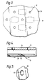
- the radially outer wall structure 22 can be seen more clearly if reference is now made to figure 2. It will be appreciated, however, that the radially inner wall structure 21 is of the same general configuration as the radially outer wall structure 22.
- the radially outer wall structure 22 comprises an outer wall 24 and an inner wall 25.
- the inner wall 25 is made up of a plurality of discreet wall elements 26 which are all of the same general rectangular configuration and are positioned adjacent each other. The majority of each wall element 26 is arranged to be equi-distant from the outer wall 24. However, the periphery of each wall element 26 is provided with a continuous flange 27 to facilitate the spacing apart of the wall element 26 and the outer wall 24. It will be seen therefore that a chamber 28 is thereby defined between each wall element 26 and the outer wall 24.
- Each wall element 26 is of cast construction and is provided with integral bolts 29 which facilitate its attachment to the outer wall 24.
- the angled effusion holes 32 which can be seen more clearly in figures 4 and 5, are not of circular cross-sectional shape. Instead they are all of the so-called race-track configuration, that is, they have two parallel sides interconnected by semi-circular cross-section portions. This shape, together with the inclination of the hole 32, ensures that air exhausted from them forms a film of cooling air over the inward surface of each wall element 26, that is, the surface which confronts the combustion process which takes place within the combustor 20. This film of cooling air assists in protecting the wall elements 26 from the effects of the high temperature gases within the combustor 20.
- each of the wall elements 26 is provided with two highly effective forms of cooling: impingement cooling and film cooling. They are therefore fully protected from the effects of the high temperatures within the combustor 20.
- a further feature of the present invention is that none of the wall elements 26 presents exposed edges to the combustion process within the combustor 20. Consequently the overheating problems which may be experienced with wall elements having such exposed edges are avoided.
- pedestals 33 are integral with the wall elements 26 and engage or terminate very close to the outer wall 24.
- the provision of the pedestals 33, which tend to be located in the central region of each wall element 26, results in a reduction in the number of the angled effusion holes 32 in each wall element 26. Consequently, the angled effusion holes 32 tend to be concentrated in the edge regions of the wall elements 26.
Landscapes
- Engineering & Computer Science (AREA)
- Chemical & Material Sciences (AREA)
- Combustion & Propulsion (AREA)
- Mechanical Engineering (AREA)
- General Engineering & Computer Science (AREA)
- Turbine Rotor Nozzle Sealing (AREA)
Abstract
Description
- This invention relates to a gas turbine engine combustor and in particular to the construction of the wall of such a combustor.
- The combustion process which takes place within the combustor of a gas turbine engine results in the combustor walls being exposed to extremely high temperatures. The alloys used in combustor wall construction are normally unable to withstand these temperatures without some form of cooling. Various combustor wall designs have been employed in the past which make use of pressurised air derived from the engine compressor for cooling purposes. In one particular wall design described in Great Britain Patent Application No 2,087,065A, the wall is made up of two parts: a continuous outer wall and an inner wall made up of a number of partially overlapping inner wall elements. The outer wall and inner wall elements are maintained in spaced apart relationship and cooling air is directed through holes in the outer wall into the space defined between them. The cooling air flows through the space to be exhausted through gaps defined between the overlapping portions of the inner wall elements. The cooling air thereby provides convection cooling as it flows between the inner wall elements and outer wall and film cooling of the inner wall elements after it has been exhausted from the gaps between inner wall elements.
- It has been found with combustion chamber walls of this type that the film cooling of the inner wall elements is not as effective as would normally be desired. This can lead to overheating of and possible damage to the exposed edges of the overlapping portions of the inner wall elements.
- It is an object of the present invention to provide a gas turbine engine combustor wall construction in which such film cooling is of improved effectiveness.
- According to the present invention, a gas turbine engine annular combustor has a radially inner wall structure and a radially outer wall structure, each wall structure compring a radially outer wall and a radially inner wall, said radially inner wall being constituted by a plurality of discreet wall elements, means being provided to maintain said wall elements and said radially outer wall in spaced apart relationship, said radially outer wall being apertured to permit the flow of cooling fluid into the spaces defined between said radially outer wall and said wall elements, each of said wall elements being apertured to facilitate the exhaustion of said cooling fluid from said spaces, means being provided to interconnect the periphery of each wall element and said outer wall said interconnection means defining a continuous wall around each wall element periphery which is integral with that periphery so that a discreet chamber is thereby defined between each of said wall elements and said radially outer wall for the flow therethrough of said cooling fluid.
- The present invention will now be described, by way of example, with reference to the accompanying drawings:
- Figure 1 is a sectional side view of the upper half of a ducted fan gas turbine engine which incorporates a combustor in accordance with the present invention;
- Figure 2 is a sectional side view of a portion of the wall of the combustor of the gas turbine engine shown in figure 1;
- Figure 3 is a view on arrow A of figure 2;
- Figure 4 is a view on an enlarged scale of a portion of the combustor wall shown in figure 2;
- Figure 5 is a view on arrow B of figure 4.
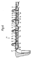
- Figure 6 is a view similar to Figure 2 showing a modified form of combustor in accordance with the present invention.
- With reference to figure 1 a ducted fan gas turbine engine generally indicated at 10 comprises, in axial flow series, an
air intake 11, apropulsive fan 12, anintermediate pressure compressor 13, ahigh pressure compressor 14,combustion equipment 15, ahigh pressure turbine 16, anintermediate pressure turbine 17, alow pressure turbine 18 and anexhaust nozzle 19. - The
gas turbine engine 10 works in the conventional manner so that air entering theintake 11 is accelerated by thefan 12 to produce two air flows: a first air flow into theintermediate pressure compressor 13 and a second airflow which provides propulsive thrust. Theintermediate pressure compressor 13 compresses the air flow directed into it before delivering that air to thehigh pressure compressor 14 where further compression takes place. - The compressed air exhausted from the
high pressure compressor 14 is directed into thecombustion equipment 15 where it is mixed with fuel and the mixture combusted. The resultant hot combustion products then expand through, and thereby drive, the high, intermediate andlow pressure turbines nozzle 19 to provide additional propulsive thrust. The high, intermediate andlow pressure turbines intermediate pressure compressors fan 12 by suitable interconnecting shafts. - The
combustion equipment 15 is constituted by anannular combustor 20 having radially inner andouter wall structures combustor 20 through a number of fuel nozzles (-not shown) located at theupstream end 23 of thecombustor 20. The fuel nozzles are circumferentially spaced around theengine 10 and serve to spray fuel into air derived from thehigh pressure compressor 14. The resultant fuel/air mixture is them combusted within thecombustor 20. - The combustion process which takes place within the
combustion 20 naturally generates a large amount of heat. It is necessary therefore to arrange that the inner andouter wall structures - The radially
outer wall structure 22 can be seen more clearly if reference is now made to figure 2. It will be appreciated, however, that the radiallyinner wall structure 21 is of the same general configuration as the radiallyouter wall structure 22. - Referring to figure 2, the radially
outer wall structure 22 comprises anouter wall 24 and aninner wall 25. Theinner wall 25 is made up of a plurality ofdiscreet wall elements 26 which are all of the same general rectangular configuration and are positioned adjacent each other. The majority of eachwall element 26 is arranged to be equi-distant from theouter wall 24. However, the periphery of eachwall element 26 is provided with acontinuous flange 27 to facilitate the spacing apart of thewall element 26 and theouter wall 24. It will be seen therefore that achamber 28 is thereby defined between eachwall element 26 and theouter wall 24. - Each
wall element 26 is of cast construction and is provided withintegral bolts 29 which facilitate its attachment to theouter wall 24. - During engine operation, some of the air exhausted from the
high pressure compressor 14 is permitted to flow over the exterior surfaces of thecombustor 20. The air providescombustor 20 cooling and some of it is directed into the interior of thecombustor 20 to assist in the combustion process. A large number ofholes 30 are provided in theouter wall 24, which can also be seen in figure 3, to permit the flow of some of this air into thechambers 28. The air passing through theholes 30 impinges upon the radially outward surfaces of thewall elements 26 as indicated by the airflow indicating arrows 31. This ensures that each of thewall elements 26 is cooled in a highly effective manner. That air is then exhausted from thechambers 28 through a plurality ofangled effusion holes 32 provided in eachwall element 26. Theeffusion holes 32 are are so angled as to be aligned in a generally downstream direction with regard to the general fluid flow through thecombustor 20. - The
angled effusion holes 32, which can be seen more clearly in figures 4 and 5, are not of circular cross-sectional shape. Instead they are all of the so-called race-track configuration, that is, they have two parallel sides interconnected by semi-circular cross-section portions. This shape, together with the inclination of thehole 32, ensures that air exhausted from them forms a film of cooling air over the inward surface of eachwall element 26, that is, the surface which confronts the combustion process which takes place within thecombustor 20. This film of cooling air assists in protecting thewall elements 26 from the effects of the high temperature gases within thecombustor 20. - It will be appreciated that although the present invention has been described with reference to
effusion holes 32 which are of race-track cross-sectional configuration, other alternative configurations may also be effective in providingsatisfactory wall element 26 cooling. - It will be seen therefore that each of the
wall elements 26 is provided with two highly effective forms of cooling: impingement cooling and film cooling. They are therefore fully protected from the effects of the high temperatures within thecombustor 20. - A further feature of the present invention is that none of the
wall elements 26 presents exposed edges to the combustion process within thecombustor 20. Consequently the overheating problems which may be experienced with wall elements having such exposed edges are avoided. - It may be desirable in certain circumstances to enhance the heat exchange relationship between the cooling air passing through the
chambers 28 and thewall elements 26. One way of readily achieving this would be to providepedestals 33 or other suitable devices to increase surface area on the surfaces of thewall elements 26 which confront theouter wall 24 as can be seen in Figure 6. Thepedestals 33 are integral with thewall elements 26 and engage or terminate very close to theouter wall 24. The provision of thepedestals 33, which tend to be located in the central region of eachwall element 26, results in a reduction in the number of theangled effusion holes 32 in eachwall element 26. Consequently, theangled effusion holes 32 tend to be concentrated in the edge regions of thewall elements 26.
Claims (10)
- A gas turbine engine annular combustor (15) having a radially inner wall structure (21) and a radially outer wall structure (22), each of said wall structures comprising a radially outer wall (24) and a radially inner wall (25), said inner wall (25) being constituted by a plurality of discreet wall elements (26), means being provided to maintain the majority of said wall elements (26) and said radially outer wall (24) in spaced apart relationship, said radially outer wall (24) being apertured to permit the flow of cooling fluid into the spaces defined between said radially outer wall (24) and said wall elements (26), each of said wall elements (26) being apertured to facilitate the exhaustion of said cooling fluid from said spaces, means (27) being provided to interconnect the periphery of each wall element (26) and said radially outer wall (24), characterised in that said interconnection means (27) defines a continuous wall around each wall element (26) periphery which is integral with that periphery so that a discreet chamber (28) is defined between each of said wall elements (26) and said radially outer wall (24) for the flow therethrough of said cooling fluid.
- A gas turbine engine combustor as claimed in claim 1 characterised in that said apertures (30) in said radially outer wall (24) are so arranged as to direct cooling fluid on to said wall elements (26) to provide impingement cooling thereof.
- A gas turbine engine combustor as claimed in claim 1 or claim 2 characterised in that said apertures (32) in each of said wall elements (25) are so arranged as to exhaust cooling fluid from said discreet chambers (28) to provide film cooling of said wall elements (25).
- A gas turbine engine combustor as claimed in claim 3 characterised in that said apertures (32) in said wall elements (25) are inclined in the general direction of fluid flow through said combustor to facilitate said film cooling of said wall elements (25).
- A gas turbine engine combustor as claimed in claim 4 characterised in that said apertures (32) in said wall elements (25) are of race-track cross-sectional configuration.
- A gas turbine engine combustor as claimed in any one preceding claim characterised in that said wall elements (25) are positioned on said outer wall (24) so as to be generally adjacent each other.
- A gas turbine engine combustor as claimed in claim 1 characterised in that the peripheral flange (27) on each of said wall elements (25) additionally constitutes said means to space apart its associated wall element (25) and said outer wall (24).
- A gas turbine engine combustor as claimed in any one preceding claim characterised in that each of said wall elements (25) is provided with integral bolts (29) to facilitate its attachment to said outer wall (24).
- A gas turbine engine combustor as claimed in any one preceding claim characterised in that each of said wall elements (25) is provided with a plurality of pedestals (33) to enhance the heat exchange relationship between said wall elements (25) and said cooling fluid flow through said spaces (28) between said wall elements (25) and said outer wall (24).
- A gas turbine engine combustor as claimed in claim 10 characterised in that each of said pedestals (33) engages said outer wall (24).
Applications Claiming Priority (3)
| Application Number | Priority Date | Filing Date | Title |
|---|---|---|---|
| GB91060855 | 1991-03-22 | ||
| GB919106085A GB9106085D0 (en) | 1991-03-22 | 1991-03-22 | Gas turbine engine combustor |
| PCT/GB1992/000201 WO1992016798A1 (en) | 1991-03-22 | 1992-02-03 | Gas turbine engine combustor |
Publications (2)
| Publication Number | Publication Date |
|---|---|
| EP0576435A1 EP0576435A1 (en) | 1994-01-05 |
| EP0576435B1 true EP0576435B1 (en) | 1995-08-23 |
Family
ID=10692006
Family Applications (1)
| Application Number | Title | Priority Date | Filing Date |
|---|---|---|---|
| EP92904247A Expired - Lifetime EP0576435B1 (en) | 1991-03-22 | 1992-02-03 | Gas turbine engine combustor |
Country Status (5)
| Country | Link |
|---|---|
| EP (1) | EP0576435B1 (en) |
| JP (1) | JPH06507468A (en) |
| DE (1) | DE69204280T2 (en) |
| GB (1) | GB9106085D0 (en) |
| WO (1) | WO1992016798A1 (en) |
Cited By (3)
| Publication number | Priority date | Publication date | Assignee | Title |
|---|---|---|---|---|
| EP2508803A2 (en) | 2011-04-06 | 2012-10-10 | Rolls-Royce plc | A cooled double walled article |
| DE102013226488A1 (en) | 2013-12-18 | 2015-06-18 | Rolls-Royce Deutschland Ltd & Co Kg | Washer of a combustion chamber shingle of a gas turbine |
| DE102016222099A1 (en) | 2016-11-10 | 2018-05-17 | Rolls-Royce Deutschland Ltd & Co Kg | Combustion chamber of a gas turbine |
Families Citing this family (19)
| Publication number | Priority date | Publication date | Assignee | Title |
|---|---|---|---|---|
| FR2723177B1 (en) * | 1994-07-27 | 1996-09-06 | Snecma | COMBUSTION CHAMBER COMPRISING A DOUBLE WALL |
| GB2298266A (en) * | 1995-02-23 | 1996-08-28 | Rolls Royce Plc | A cooling arrangement for heat resistant tiles in a gas turbine engine combustor |
| US5758503A (en) * | 1995-05-03 | 1998-06-02 | United Technologies Corporation | Gas turbine combustor |
| DE19516798A1 (en) * | 1995-05-08 | 1996-11-14 | Abb Management Ag | Premix burner with axial or radial air flow |
| FR2752916B1 (en) * | 1996-09-05 | 1998-10-02 | Snecma | THERMAL PROTECTIVE SHIRT FOR TURBOREACTOR COMBUSTION CHAMBER |
| US6079199A (en) * | 1998-06-03 | 2000-06-27 | Pratt & Whitney Canada Inc. | Double pass air impingement and air film cooling for gas turbine combustor walls |
| DE102007018061A1 (en) | 2007-04-17 | 2008-10-23 | Rolls-Royce Deutschland Ltd & Co Kg | Gas turbine combustion chamber wall |
| US20100263386A1 (en) * | 2009-04-16 | 2010-10-21 | General Electric Company | Turbine engine having a liner |
| DE102009032277A1 (en) | 2009-07-08 | 2011-01-20 | Rolls-Royce Deutschland Ltd & Co Kg | Combustion chamber head of a gas turbine |
| CH703657A1 (en) * | 2010-08-27 | 2012-02-29 | Alstom Technology Ltd | Method for operating a burner arrangement and burner arrangement for implementing the process. |
| JP2012145098A (en) * | 2010-12-21 | 2012-08-02 | Toshiba Corp | Transition piece, and gas turbine |
| US20120180492A1 (en) * | 2011-01-14 | 2012-07-19 | General Electric Company | Apparatus for vibration support in combustors and method for forming apparatus |
| EP2559942A1 (en) | 2011-08-19 | 2013-02-20 | Rolls-Royce Deutschland Ltd & Co KG | Gas turbine combustion chamber head with cooling and damping |
| JP5821550B2 (en) | 2011-11-10 | 2015-11-24 | 株式会社Ihi | Combustor liner |
| DE102012016493A1 (en) | 2012-08-21 | 2014-02-27 | Rolls-Royce Deutschland Ltd & Co Kg | Gas turbine combustor with impingement-cooled bolts of the combustion chamber shingles |
| DE102012025375A1 (en) | 2012-12-27 | 2014-07-17 | Rolls-Royce Deutschland Ltd & Co Kg | Method for arranging impingement cooling holes and effusion holes in a combustion chamber wall of a gas turbine |
| DE102013003444A1 (en) | 2013-02-26 | 2014-09-11 | Rolls-Royce Deutschland Ltd & Co Kg | Impact-cooled shingle of a gas turbine combustor with extended effusion holes |
| DE102013222932A1 (en) | 2013-11-11 | 2015-05-28 | Rolls-Royce Deutschland Ltd & Co Kg | Gas turbine combustion chamber with shingle for carrying out a spark plug |
| JP2024091028A (en) * | 2022-12-23 | 2024-07-04 | 川崎重工業株式会社 | Combustor for gas turbine |
Family Cites Families (7)
| Publication number | Priority date | Publication date | Assignee | Title |
|---|---|---|---|---|
| GB1093515A (en) * | 1966-04-06 | 1967-12-06 | Rolls Royce | Method of producing combustion chambers and similar components for gas turbine engines |
| US3422620A (en) * | 1967-05-04 | 1969-01-21 | Westinghouse Electric Corp | Combustion apparatus |
| GB1552132A (en) * | 1975-11-29 | 1979-09-12 | Rolls Royce | Combustion chambers for gas turbine engines |
| GB2087065B (en) * | 1980-11-08 | 1984-11-07 | Rolls Royce | Wall structure for a combustion chamber |
| US4422300A (en) * | 1981-12-14 | 1983-12-27 | United Technologies Corporation | Prestressed combustor liner for gas turbine engine |
| GB2204672B (en) * | 1987-05-06 | 1991-03-06 | Rolls Royce Plc | Combustor |
| GB2221979B (en) * | 1988-08-17 | 1992-03-25 | Rolls Royce Plc | A combustion chamber for a gas turbine engine |
-
1991
- 1991-03-22 GB GB919106085A patent/GB9106085D0/en active Pending
-
1992
- 1992-02-03 JP JP4504028A patent/JPH06507468A/en active Pending
- 1992-02-03 WO PCT/GB1992/000201 patent/WO1992016798A1/en active IP Right Grant
- 1992-02-03 DE DE69204280T patent/DE69204280T2/en not_active Expired - Lifetime
- 1992-02-03 EP EP92904247A patent/EP0576435B1/en not_active Expired - Lifetime
Cited By (5)
| Publication number | Priority date | Publication date | Assignee | Title |
|---|---|---|---|---|
| EP2508803A2 (en) | 2011-04-06 | 2012-10-10 | Rolls-Royce plc | A cooled double walled article |
| US9010124B2 (en) | 2011-04-06 | 2015-04-21 | Rolls-Royce Plc | Cooled double walled article |
| DE102013226488A1 (en) | 2013-12-18 | 2015-06-18 | Rolls-Royce Deutschland Ltd & Co Kg | Washer of a combustion chamber shingle of a gas turbine |
| EP2886961A1 (en) | 2013-12-18 | 2015-06-24 | Rolls-Royce Deutschland Ltd & Co KG | Washer of a combustion chamber shingle of a gas turbine |
| DE102016222099A1 (en) | 2016-11-10 | 2018-05-17 | Rolls-Royce Deutschland Ltd & Co Kg | Combustion chamber of a gas turbine |
Also Published As
| Publication number | Publication date |
|---|---|
| GB9106085D0 (en) | 1991-05-08 |
| WO1992016798A1 (en) | 1992-10-01 |
| EP0576435A1 (en) | 1994-01-05 |
| DE69204280T2 (en) | 1996-01-25 |
| DE69204280D1 (en) | 1995-09-28 |
| JPH06507468A (en) | 1994-08-25 |
Similar Documents
| Publication | Publication Date | Title |
|---|---|---|
| US5435139A (en) | Removable combustor liner for gas turbine engine combustor | |
| EP0576435B1 (en) | Gas turbine engine combustor | |
| EP0471437B1 (en) | Gas turbine engine combustor | |
| EP0471438B1 (en) | Gas turbine engine combustor | |
| US6408628B1 (en) | Wall elements for gas turbine engine combustors | |
| US5271219A (en) | Gas turbine engine combustor | |
| JP4433529B2 (en) | Multi-hole membrane cooled combustor liner | |
| US6470685B2 (en) | Combustion apparatus | |
| EP1104871B1 (en) | Combustion chamber for a gas turbine engine | |
| US8544277B2 (en) | Turbulated aft-end liner assembly and cooling method | |
| US6170266B1 (en) | Combustion apparatus | |
| EP1347152B1 (en) | Cooled turbine nozzle sector | |
| US5531568A (en) | Turbine blade | |
| EP3156731B1 (en) | Combustor for a gas turbine engine | |
| EP2846097B1 (en) | A gas turbine combustion chamber with tiles having film cooling apertures | |
| GB2353589A (en) | Combustor wall arrangement with air intake port | |
| CA2920188C (en) | Combustor dome heat shield | |
| EP1074792A1 (en) | Turbine combustor arrangement | |
| US20020056277A1 (en) | Double wall combustor arrangement | |
| US10823413B2 (en) | Combustion chamber assembly and a combustion chamber segment | |
| US20050034399A1 (en) | Double wall combustor tile arrangement | |
| GB2356042A (en) | Improvements in or relating to wall elements for gas turbine engines | |
| GB2415017A (en) | Heat shield for attachment to a casing of a gas turbine engine |
Legal Events
| Date | Code | Title | Description |
|---|---|---|---|
| PUAI | Public reference made under article 153(3) epc to a published international application that has entered the european phase |
Free format text: ORIGINAL CODE: 0009012 |
|
| 17P | Request for examination filed |
Effective date: 19930914 |
|
| AK | Designated contracting states |
Kind code of ref document: A1 Designated state(s): DE FR GB |
|
| 17Q | First examination report despatched |
Effective date: 19950112 |
|
| GRAA | (expected) grant |
Free format text: ORIGINAL CODE: 0009210 |
|
| AK | Designated contracting states |
Kind code of ref document: B1 Designated state(s): DE FR GB |
|
| REF | Corresponds to: |
Ref document number: 69204280 Country of ref document: DE Date of ref document: 19950928 |
|
| ET | Fr: translation filed | ||
| PLBI | Opposition filed |
Free format text: ORIGINAL CODE: 0009260 |
|
| PLBF | Reply of patent proprietor to notice(s) of opposition |
Free format text: ORIGINAL CODE: EPIDOS OBSO |
|
| 26 | Opposition filed |
Opponent name: SIEMENS AG ABTLG. ZFE GR PA 3 Effective date: 19960522 |
|
| PLBF | Reply of patent proprietor to notice(s) of opposition |
Free format text: ORIGINAL CODE: EPIDOS OBSO |
|
| PLBO | Opposition rejected |
Free format text: ORIGINAL CODE: EPIDOS REJO |
|
| PLBN | Opposition rejected |
Free format text: ORIGINAL CODE: 0009273 |
|
| STAA | Information on the status of an ep patent application or granted ep patent |
Free format text: STATUS: OPPOSITION REJECTED |
|
| 27O | Opposition rejected |
Effective date: 19980424 |
|
| REG | Reference to a national code |
Ref country code: GB Ref legal event code: IF02 |
|
| PLAB | Opposition data, opponent's data or that of the opponent's representative modified |
Free format text: ORIGINAL CODE: 0009299OPPO |
|
| PGFP | Annual fee paid to national office [announced via postgrant information from national office to epo] |
Ref country code: FR Payment date: 20110302 Year of fee payment: 20 Ref country code: DE Payment date: 20110218 Year of fee payment: 20 |
|
| PGFP | Annual fee paid to national office [announced via postgrant information from national office to epo] |
Ref country code: GB Payment date: 20110217 Year of fee payment: 20 |
|
| REG | Reference to a national code |
Ref country code: DE Ref legal event code: R071 Ref document number: 69204280 Country of ref document: DE |
|
| REG | Reference to a national code |
Ref country code: DE Ref legal event code: R071 Ref document number: 69204280 Country of ref document: DE |
|
| REG | Reference to a national code |
Ref country code: GB Ref legal event code: PE20 Expiry date: 20120202 |
|
| PG25 | Lapsed in a contracting state [announced via postgrant information from national office to epo] |
Ref country code: DE Free format text: LAPSE BECAUSE OF EXPIRATION OF PROTECTION Effective date: 20120204 |
|
| PG25 | Lapsed in a contracting state [announced via postgrant information from national office to epo] |
Ref country code: GB Free format text: LAPSE BECAUSE OF EXPIRATION OF PROTECTION Effective date: 20120202 |