EP1074792A1 - Turbine combustor arrangement - Google Patents
Turbine combustor arrangement Download PDFInfo
- Publication number
- EP1074792A1 EP1074792A1 EP00306279A EP00306279A EP1074792A1 EP 1074792 A1 EP1074792 A1 EP 1074792A1 EP 00306279 A EP00306279 A EP 00306279A EP 00306279 A EP00306279 A EP 00306279A EP 1074792 A1 EP1074792 A1 EP 1074792A1
- Authority
- EP
- European Patent Office
- Prior art keywords
- diffuser
- bled
- combustor
- duct
- air
- Prior art date
- Legal status (The legal status is an assumption and is not a legal conclusion. Google has not performed a legal analysis and makes no representation as to the accuracy of the status listed.)
- Granted
Links
Images


Classifications
-
- F—MECHANICAL ENGINEERING; LIGHTING; HEATING; WEAPONS; BLASTING
- F23—COMBUSTION APPARATUS; COMBUSTION PROCESSES
- F23R—GENERATING COMBUSTION PRODUCTS OF HIGH PRESSURE OR HIGH VELOCITY, e.g. GAS-TURBINE COMBUSTION CHAMBERS
- F23R3/00—Continuous combustion chambers using liquid or gaseous fuel
- F23R3/02—Continuous combustion chambers using liquid or gaseous fuel characterised by the air-flow or gas-flow configuration
- F23R3/04—Air inlet arrangements
-
- F—MECHANICAL ENGINEERING; LIGHTING; HEATING; WEAPONS; BLASTING
- F23—COMBUSTION APPARATUS; COMBUSTION PROCESSES
- F23R—GENERATING COMBUSTION PRODUCTS OF HIGH PRESSURE OR HIGH VELOCITY, e.g. GAS-TURBINE COMBUSTION CHAMBERS
- F23R3/00—Continuous combustion chambers using liquid or gaseous fuel
- F23R3/28—Continuous combustion chambers using liquid or gaseous fuel characterised by the fuel supply
- F23R3/34—Feeding into different combustion zones
- F23R3/346—Feeding into different combustion zones for staged combustion
-
- F—MECHANICAL ENGINEERING; LIGHTING; HEATING; WEAPONS; BLASTING
- F23—COMBUSTION APPARATUS; COMBUSTION PROCESSES
- F23R—GENERATING COMBUSTION PRODUCTS OF HIGH PRESSURE OR HIGH VELOCITY, e.g. GAS-TURBINE COMBUSTION CHAMBERS
- F23R2900/00—Special features of, or arrangements for continuous combustion chambers; Combustion processes therefor
- F23R2900/03041—Effusion cooled combustion chamber walls or domes
-
- Y—GENERAL TAGGING OF NEW TECHNOLOGICAL DEVELOPMENTS; GENERAL TAGGING OF CROSS-SECTIONAL TECHNOLOGIES SPANNING OVER SEVERAL SECTIONS OF THE IPC; TECHNICAL SUBJECTS COVERED BY FORMER USPC CROSS-REFERENCE ART COLLECTIONS [XRACs] AND DIGESTS
- Y02—TECHNOLOGIES OR APPLICATIONS FOR MITIGATION OR ADAPTATION AGAINST CLIMATE CHANGE
- Y02T—CLIMATE CHANGE MITIGATION TECHNOLOGIES RELATED TO TRANSPORTATION
- Y02T50/00—Aeronautics or air transport
- Y02T50/60—Efficient propulsion technologies, e.g. for aircraft
Definitions
- the present invention relates generally to a combustor arrangement for a gas turbine engine and in particular to improvements to gas turbine engine combustors incorporating bled diffusers.
- compressed air is delivered from a compressor to a combustor where it is mixed with fuel and is burnt within the combustor to produce a high temperature and energy gas stream.
- This high temperature and energy gas stream then flows into and through a turbine system which extracts energy from the stream to drive the upstream compressors which are drivingly connected to the turbines.
- the turbines may also extract energy from the gas stream to drive a fan, propeller or other equipment for example an electrical generator.
- a typical diffuser comprises a diverging duct with an increasing cross section through which the air from the compressor flows. As well as diffusing the air flow from the compressor the diffuser also distributes the air flow across the annular cross section of the combustor.
- a problem with such diffusers is that a boundary layer develops adjacent to the walls of the diffuser.
- the air flow within this boundary layer has a lower velocity than the main flow through the diffuser.
- the size of the boundary layer increases as the air flows through the diffuser with the result that the airflow from the diffuser has a non uniform cross sectional velocity profile.
- Such a variation in air flow velocity is undesirable for stable and efficient combustion.
- a further problem is that the angle of divergence of the diffuser duct, and so rate of diffusion, is limited by the occurrence of separation of the boundary layer at the diffuser wall which induces flow losses. Consequently to achieve a significant amount of diffusion of the air flow and/or to distribute the air flow over a significant combustor cross sectional area a conventional diffuser must be relatively long.
- the available length for the diffuser however is often limited in modern gas turbine engines. This is a particular problem for modern double annular staged fuel combustor arrangements which have a large cross sectional area and require a uniform cross sectional velocity profile
- bled diffuser arrangements have been proposed.
- the boundary layer adjacent to the diffuser duct walls is bled from the diffuser. This reduces the size of the boundary layer so improving the uniformity of the cross sectional velocity profile and allowing greater diffuser duct angles, and so diffusion rates, to be used without boundary layer separation.
- Such bled diffusers are more efficient and have improved performance as compared to conventional diffusers.
- Various different types of such bled diffusers exist including vortex diffusers and diffusers with perforated duct walls.
- a combustor arrangement for a gas turbine engine comprising a combustion chamber, fuel nozzles, and a bled diffuser located upstream of said combustion chamber to, in use, direct an airflow from an upstream compressor into the combustor with the fuel nozzles arranged in use to supply fuel into the combustion chamber where it is mixed and combusted with the airflow from the compressor, the bled diffuser adapted to bleed off a portion of said airflow from a main airflow into the combustion chamber; characterised in that at least one bleed duct is connected to the bled diffuser to, in use, return and direct air bled from the diffuser to a main gas flow through the engine at a location downstream of the fuel nozzles.
- the at least one bleed duct is arranged to supply the air bled from the diffuser to a part of the gas turbine engine downstream of the fuel nozzles so that, in use, the air bled from the diffuser provides cooling of said part of the gas turbine engine.
- the combustor may be disposed upstream of a turbine of a gas turbine engine, the at least one bleed duct connected to the turbine to, in use, return and direct the air bled from the diffuser to the main gas flow through the turbine.
- each vane of the array Internal cooling passages are defined which exhaust into the main airflow, the at least one bleed duct interconnects the bled diffuser with the internal cooling passages of said vanes so that in use air bled from the diffuser exhausts into the main gas flow through the internal vane cooling passages.
- the internal cooling passages may be defined in an aerofoil portion of the vane.
- the vane may comprise a platform and aerofoil and the internal cooling passages may be defined in the platform of the vane.
- the at least one bleed duct is located radially inwardly of the combustion chamber.
- the at least one bleed duct is located radially outwardly of the combustion chamber.
- the bled diffuser may comprise a vortex controlled bled diffuser.
- the combustor is of a staged combustor type.
- the bled diffuser may be defined by radially inner and outer diffuser duct walls and, in use, the main airflow flows between these inner and outer diffuser duct walls, at least one opening is defined in each of the diffuser duct walls through which, in use, air is bled.
- the at least one duct extends between the inner and outer diffuser duct walls to, in use, interconnect the air bled through the openings defined in each of the diffuser duct walls.
- the at least one bleed duct comprises at least two bleed ducts, the first bleed duct interconnected with the opening in the inner diffuser duct wall and the second bleed duct interconnected with the opening in the outer diffuser duct wall.
- the combustor arrangement may further comprise a combustor casing which at least in part is of a double walled construction defining the at least one bleed duct.
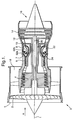
- a ducted fan gas turbine engine 3 comprises, in axial flow series an air intake 5, a propulsive fan, an intermediate pressure compressor 4, a high pressure compressor 6 a combustor arrangement 8, a high pressure turbine 10, an intermediate pressure turbine 12, a low pressure turbine 14, and an exhaust nozzle 16.
- the compressors 4,6, and turbines 10,12,14 are of an axial flow type and comprise alternate rotary stages that rotate about a central engine axis 1 and stationary vanes. The invention however is equally applicable to other conventional gas turbine engine arrangements including those which do not incorporate a separate intermediate pressure compressor and turbine.
- the gas turbine engine 3 works in a conventional manner so that air entering the intake 5 is accelerated by the fan 2. Air exiting the fan 2 is split into two flows. A first air flow flows through a bypass duct 18 and exhausts the engine to provide propulsive thrust. The second air flow enters the intermediate pressure compressor 4. The intermediate pressure compressor compresses the air flow directed into it before delivering the air to the high pressure compressor 6 where further compression takes place. The compressed air exits the high pressure compressor 6 and enters the combustor arrangement through a diffuser 7. Within the diffuser the flow area is increased, reducing the velocity of the airflow and increasing its static pressure. The diffuser 7 also distributes the airflow radially across the radial depth of the combustor arrangement and stabilises the airflow into the combustor arrangement.
- the air is mixed with fuel supplied via fuel nozzles 52a,52b and the mixture combusted.
- the resultant hot combustion gases then expand through, and thereby drive, the high 10, intermediate 12 and low pressure 14 turbines causing them to rotate about the engine axis 1, before being exhausted through the nozzle 16 to provide additional propulsive thrust.
- the high 10, intermediate 12, and low 14 pressure turbines are drivingly interconnected respectively with the high 6, intermediate 4 pressure compressors and fan 2 via respective interconnecting shafts 24,22,20.
- the direction of airflow through the engine 3 is shown by arrow A and the terms upstream and downstream used throughout this description are used with reference to this general flow direction.
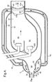
- the combustor arrangement is shown in more detail in figure 2.
- the combustor arrangement comprises radially inner and outer annular combustor casing walls 48,49. Within the annular space between these walls 48,49 a further pair of walls 50,51 define an annular combustion chamber. Fuel is directed into the combustion chamber through a number of fuel nozzles 52a,52b located at the upstream end of the combustion chamber. The fuel nozzles 52a,52b spray fuel into air delivered from the high pressure compressor 6 which enters the combustion chamber through suitable ports (not shown) within the combustion chamber walls 50,51. The resulting fuel air mixture is then combusted. The resultant high energy combustion products discharge through the downstream end 54 of the combustion chamber and combustor arrangement through an annular array of combustor outlet guide vanes / high pressure turbine inlet guide vanes 58.
- the combustor arrangement shown is of a staged double annular type well known in the art.
- the fuel nozzles 52a, 52b are arranged in two distinct annular arrays/sets which are radially spaced within the chamber. Each array/set of fuel nozzles comprises a number of fuel nozzles which are circumferentially spaced in an annulus around the combustor 8.
- the radially inner set of fuel nozzles 52b which in this embodiment are the pilot fuel nozzles, supply fuel to a first, pilot, region 62 of the combustion chamber whilst the outer, main, fuel nozzles 52a supply fuel to an outer, main, region 64.
- the main 64 and pilot 62 regions are partially separated by a further wall 55.
- Air is delivered to the combustor from the high pressure compressor 6 via outlet vanes 28 of the compressor 6 and a diffuser 7 located on the upstream end of the combustor.
- the diffuser comprises a first divergent annular duct 66 defined by divergent inner and outer annular diffuser duct walls 30, and a second divergent duct 68 defined by divergent inner and outer diffuser duct walls 32 downstream of the first duct 66. Downstream of the downstream end of the first duct 66 there is a sudden enlargement of the flow area essentially defined by an inner and outer annular fence 34 located on and extending radially from the upstream ends of the inner and outer walls 32 which define the second duct 68. Between the downstream end of the first duct 66 and the fence 34 there are defined inner and outer annular openings 36 which lead to inner and outer annular chambers 44b and 44a respectively.
- flow across the openings 36 creates a usually toroidal vortex within each of the chambers 44a and 44b, causing the flow to diffuse. Further diffusion takes place immediately downstream of the fence 34 associated with a further pair of vortices created downstream of the fence 34, i.e. in the corner between the fence and the upstream portion of the duct 68. Further downstream the flow reattaches to the walls 32 and further diffusion continues through the duct 68.
- a vortex controlled diffuser larger divergent duct wall angles can be utilised and more rapid diffusion can be produced without the normal boundary layer separation at the diffuser outlet occurring. Such boundary layer separation limits the efficient achievable rate of diffusion of conventional diffusers and distorting the velocity profile of the flow discharged from the diffuser which can adversely affect combustion downstream of the diffuser.
- ducts 42 interconnect the outer chamber 44a with the inner chamber 44b. These ducts 42 are housed within an annular array of diffuser bleed strut vanes 38 which extend between the inner and outer walls 32 of the downstream diffuser duct 68.
- the diffuser vane 38 may also support an annular splitter 40, as shown in this embodiment, which aids in distributing the air radially within the combustor.
- a main bleed duct 46 is connected to chamber 44b in order to bleed air from both the inner and outer chambers 44a,44b.
- This main bleed duct is disposed radially inside of the combustor and extends downstream towards the downstream end of the combustor to the combustor outlet guide vanes 56.
- bleeding the air from the diffuser walls 30,32 removes the boundary layer that is generated adjacent to the diffuser duct walls 30,32.
- This boundary layer being of a relatively low velocity and low energy, relative to the main portion of the flow through the duct 66,68, and thus adversely affecting the velocity distribution of the flow.
- the boundary layer is also liable to separation which reduces the efficiency of the diffuser. Removing the boundary layer from the diffuser flow is therefore advantageous.
- the bled air is cooler than the temperature at the combustor outlet 54 and upstream parts of the turbines 10,12,14 the bled air is hotter than the bulk air flow through the diffuser duct 66,68 since the bled air originates from the boundary layer region which is hotter than the bulk flow.
- heat transfer occurs which reduces the temperature of the bled boundary layer air by virtue of the lower bulk air temperature surrounding the main bleed duct 46.
- the internal cooling passages 58 are connected to, and supply the bleed air to, effusion cooling holes within the rear downstream portion and trailing edge of the vanes 56.
- the bleed air being at a lower temperature than that of or adjacent to the vanes 56 so that the bleed air cools the vanes 56. Due to the aerodynamic profile of the vanes 56 the static pressure at the rear downstream portion and trailing edge of the vanes is lower than that within the diffuser chamber 44a,44b. Air will therefore be bled from the chamber 44a,44b via the main bleed duct 46 and internal vane cooling passages 58 to be discharged through the rear downstream portion and trailing edge effusion cooling holes 60 back into the main flow through the engine, as shown by the flow arrows in figure 2.
- the air that is bled from the diffuser to improve the diffuser performance is also advantageously used to provide cooling of the outlet guide vanes 56 and also provide film cooling of the outer surface of the vanes 56 to protect the surface of the vanes 56.
- the air bled from the diffuser is also returned to the main flow at the upstream end of the high pressure turbine 10.
- the bled air, which has been compressed by the upstream compressors 6 is therefore not wasted and will flow through the high pressure 10 and other downstream turbines 12,14 where it will do some useful work. Consequently the performance loss associated with bleeding high pressure air from the main flow is minimised.
- conventionally dedicated cooling air is used to cool the outlet guide vanes 56.
- the internal cooling passages 58 within the vanes 56 are provided within an aerofoil portion of the vane 56.
- the inner and outer platform portions 57a,57b of the vane 56 which define the outer walls of the flow path through the vane 56 are also exposed to the high temperature gas flow. It is known to provide conventionally derived cooling air to these portions of the vane using internal cooling passages and effusion cooling holes within these vane platforms.
- the main bleed duct may be connected to these platform internal cooling passages to provide cooling of the vane platforms 57a,57b.
- the main bleed duct 46 of figure 2 is replaced with an alternative main bleed duct 45.
- This bleed duct 45 similarly interconnects the diffuser 7 with the combustor outlet guide vanes 56 in order to bled air from the inner and outer chambers 44a,44b.
- the bleed duct 45 is disposed radially outside of the combustor and is connected to chamber 44a. Air from the inner chamber 44b is bled through duct 42 into the outer chamber 44a and into the bleed duct 45.
- two sets of inner 45 and outer 46 bleed ducts are provided. These interconnect and bleed the respective inner 44b and outer 44a chambers of the diffuser 7 and supply the bled air to inner and outer ends of internal cooling passages 58 within the combustor outlet guide vanes 56.
- the duct 42 (shown in figure 2) and diffuser bleed strut vanes 38 are now no longer required. The flow through the diffuser duct 68 is thereby improved and the diffuser simplified. There is also a weight reduction, however this is offset, at least partially, by the requirement to provide two main bleed ducts 45,46 rather than one.
- the flow characteristics of the combustor may result in the static pressure at the downstream end 54 of the combustor being sufficiently low, as compared to the pressure of the air bled from the diffuser 7. If this is the case then, as shown in figure 5, the air bled from the diffuser can be returned to the main flow at this point 54, with a duct 47 interconnecting the diffuser 7 and the downstream end 54 of the combustor.
- the air bled from the diffuser can also be returned to other suitable locations within the downstream portions of the gas turbine engine 3, for example other vanes or blades within the turbine stages or elsewhere, with the main bleed duct connecting to these locations.
- the air bled from the diffuser being similarly used to provide cooling at these locations.
- the bleed ducts 45,46,47 are separate from the combustor walls 48,49. It will be appreciated however that if the respective walls 45,48 are of a double walled construction then the ducts 45,46,47 can be incorporated with the walls, with the air bled from the diffuser 7 flowing within the space between the double walls.
- staged double annular combustors Due to their superior performance bled diffusers are most applicable for use with staged double annular combustors. Such combustors place considerable demands on the diffuser performance due to the considerable radial cross section over which the inlet air must be distributed in such combustors, their requirement for a particularly uniform inlet airflow, and the relatively short axial length available for the diffuser. In addition it is often difficult to adequately supply air to the burners of such combustors. Consequently, as described in the embodiments the invention is most applicable for use with staged combustors since these are most likely to incorporate a bled diffuser. It will be appreciated though that the invention can be equally applied to other types of combustors which incorporate a bled diffuser.
- the combustor defined by walls 48,49,50,51, diffuser and bleed ducts 46,45,47 have all been described as of an annular arrangement disposed around the engine axis 1. Such annular combustor arrangements are the most typical in modern gas turbine engines. It will be appreciated however that other combustor arrangements are known. For example the annular combustion chamber defined walls 50,49 could be replaced by a number of individual cylindrical combustion chambers, or cans disposed circumferentially within the combustor. A non annular diffuser arrangement is also possible and known. Such a diffuser comprising a number of separate diffuser ducts.
- the bleed duct 46,45,47 diffuser may also comprise a number of individual ducts rather than the single annular ducts shown and described in the particular embodiments.
Landscapes
- Engineering & Computer Science (AREA)
- Chemical & Material Sciences (AREA)
- Combustion & Propulsion (AREA)
- Mechanical Engineering (AREA)
- General Engineering & Computer Science (AREA)
- Structures Of Non-Positive Displacement Pumps (AREA)
Abstract
Description
Claims (15)
- A combustor arrangement (8) for a gas turbine engine (3) (3) comprising a combustion chamber, fuel nozzles (52a, 52b), and a bled diffuser (7) located upstream of said combustion chamber to, in use, direct an airflow from an upstream compressor (6) into the combustor (8) with the fuel nozzles (52a, 52b) arranged in use to supply fuel into the combustion chamber where it is mixed and combusted with the airflow from the compressor (6), the bled diffuser (7) adapted to bleed off a portion of said airflow from a main airflow into the combustion chamber;
characterised in that at least one bleed duct (46) is connected to the bled diffuser (7) to, in use, return and direct air bled from the diffuser (7) to a main gas flow through the engine at a location downstream of the fuel nozzles (52a, 52b). - A combustor arrangement (8) as claimed in claim 1 characterised in that the at least one bleed duct (46) is arranged to supply the air bled from the diffuser (7) to a part of the gas turbine engine (3) downstream of the fuel nozzles (52a, 52b) so that, in use, the air bled from the diffuser (7) provides cooling of said part of the gas turbine engine (3).
- A combustor arrangement (8) as claimed in claim 1 or 2 characterised in that the combustor is disposed upstream of a turbine (12, 14, 16) of a gas turbine engine (3), the at least one bleed duct (46) connected to the turbine to, in use, return and direct the air bled from the diffuser (7) to the main gas flow through the turbine (12, 14, 16).
- A combustor arrangement (8) as claimed in claim 1 or 2 characterised in that at the downstream end (54) of the combustion chamber there is an array of outlet guide vanes (56), within each vane (56) of the array internal cooling passages (58) are defined which exhaust into the main gas flow, the at least one bleed duct (46) interconnects the bled diffuser (7) with the internal cooling passages (58) of said vanes (56) so that in use air bled from the diffuser (7) exhausts into the main gas flow through the internal vane cooling passages (58).
- A combustor arrangement (8) as claimed in claim 4 characterised in that the internal cooling passages (58) are defined in an aerofoil portion of the vane (56).
- A combustor arrangement (8) as claimed in claim 4 characterised in that the vane (56) comprises a platform (57a, 57b) and aerofoil, the internal cooling passages (58) are defined in the platform (57a, 57b) of the vane (56).
- A combustor arrangement (8) as claimed in any one of claims 4 to 6 characterised in that the internal cooling passages (58) exhaust adjacent to a downstream portion of the vanes (56).
- A combustor arrangement (8) as claimed in any preceding claim characterised in that the at least one bleed duct (46) is located radially inwardly of the combustion chamber.
- A combustor arrangement (8) as claimed in any one of claims 1 to 5 characterised in that the at least one bleed duct (46) is located radially outwardly of the combustion chamber.
- A combustor arrangement (8) as claimed in any preceding claim characterised in that the bled diffuser (7) comprises a vortex controlled bled diffuser (7).
- A combustor arrangement (8) as claimed in any preceding claim characterised in that the combustor is of a staged combustor type.
- A combustor arrangement (8) as claimed in any preceding claim characterised in that the bled diffuser (7) is defined by radially inner and outer diffuser duct walls (30, 32) and, in use, the main airflow flows between these inner and outer diffuser duct walls (30, 32), at least one opening (36) is defined in each of the diffuser duct walls (30, 32) through which, in use, air is bled.
- A combustor arrangement (8) as claimed in claim 12 characterised in that at least one duct (42) extends between the inner and outer diffuser duct walls (30, 32) to, in use, interconnect the air bled through the openings (36) defined in each of the diffuser duct walls (30, 32).
- A combustor arrangement (8) as claimed in claim 12 characterized in that the at least one bleed duct (46) comprises at least two bleed ducts (45, 46), the first bleed duct (46) interconnected with the opening (36) in the inner diffuser duct wall (30) and the second bleed duct (45) interconnected with the opening (36) in the outer diffuser duct wall (32).
- A combustor arrangement (8) as claimed in any preceding claim characterised in that the combustor arrangement (8) further comprising a combustor casing (48, 49) which at least in part is of a double walled construction defining the at least one bleed duct (46).
Applications Claiming Priority (2)
| Application Number | Priority Date | Filing Date | Title |
|---|---|---|---|
| GBGB9917957.4A GB9917957D0 (en) | 1999-07-31 | 1999-07-31 | A combustor arrangement |
| GB9917957 | 1999-07-31 |
Publications (2)
| Publication Number | Publication Date |
|---|---|
| EP1074792A1 true EP1074792A1 (en) | 2001-02-07 |
| EP1074792B1 EP1074792B1 (en) | 2006-11-08 |
Family
ID=10858263
Family Applications (1)
| Application Number | Title | Priority Date | Filing Date |
|---|---|---|---|
| EP00306279A Expired - Lifetime EP1074792B1 (en) | 1999-07-31 | 2000-07-24 | Turbine combustor arrangement |
Country Status (4)
| Country | Link |
|---|---|
| US (1) | US6334297B1 (en) |
| EP (1) | EP1074792B1 (en) |
| DE (1) | DE60031744T2 (en) |
| GB (1) | GB9917957D0 (en) |
Cited By (10)
| Publication number | Priority date | Publication date | Assignee | Title |
|---|---|---|---|---|
| EP1426688A1 (en) * | 2002-11-19 | 2004-06-09 | General Electric Company | Combustor inlet diffuser with boundary layer blowing |
| EP1431516A2 (en) | 2002-12-17 | 2004-06-23 | Rolls Royce Plc | Diffuser arrangement |
| EP1508747A1 (en) * | 2003-08-18 | 2005-02-23 | Siemens Aktiengesellschaft | Gas turbine diffusor and gas turbine for the production of energy |
| EP2615373A1 (en) * | 2012-01-13 | 2013-07-17 | General Electric Company | System and Method for Supplying a Working Fluid to a Combustor |
| WO2014052632A1 (en) * | 2012-09-26 | 2014-04-03 | United Technologies Corporation | Gas turbine engine combustor |
| CN103868099A (en) * | 2012-12-13 | 2014-06-18 | 中航商用航空发动机有限责任公司 | Aerial engine combustion chamber and aerial engine comprising same |
| WO2014099074A3 (en) * | 2012-09-26 | 2014-08-21 | United Technologies Corporation | Gas turbine engine combustor with integrated combustor vane |
| EP3109550A1 (en) * | 2015-06-19 | 2016-12-28 | Rolls-Royce Corporation | Turbine cooled cooling air by tubular arrangement |
| EP3184904A1 (en) * | 2015-12-22 | 2017-06-28 | General Electric Company | Staged fuel and air injection in combustion systems of gas turbines |
| CN109073222A (en) * | 2016-04-25 | 2018-12-21 | 三菱重工业株式会社 | Compressor diffuser and gas turbine |
Families Citing this family (31)
| Publication number | Priority date | Publication date | Assignee | Title |
|---|---|---|---|---|
| US6564555B2 (en) * | 2001-05-24 | 2003-05-20 | Allison Advanced Development Company | Apparatus for forming a combustion mixture in a gas turbine engine |
| FR2829228B1 (en) * | 2001-08-28 | 2005-07-15 | Snecma Moteurs | ANNULAR COMBUSTION CHAMBER WITH DOUBLE HEADED HEAD |
| US6775983B2 (en) * | 2002-05-21 | 2004-08-17 | General Electric Company | Flow control device for a combustor |
| EP1508680A1 (en) * | 2003-08-18 | 2005-02-23 | Siemens Aktiengesellschaft | Diffuser located between a compressor and a combustion chamber of a gasturbine |
| US6971241B2 (en) * | 2003-11-10 | 2005-12-06 | Honeywell International Inc. | Dual mode power unit having a combustor bypass system |
| FR2880391A1 (en) * | 2005-01-06 | 2006-07-07 | Snecma Moteurs Sa | DIFFUSER FOR AN ANNULAR COMBUSTION CHAMBER, IN PARTICULAR FOR AN AIRCRAFT TURBOMOTOR |
| US7870739B2 (en) * | 2006-02-02 | 2011-01-18 | Siemens Energy, Inc. | Gas turbine engine curved diffuser with partial impingement cooling apparatus for transitions |
| RU2343356C1 (en) * | 2007-05-21 | 2009-01-10 | Федеральное государственное унитарное предприятие "Центральный институт авиационного моторостроения имени П.И. Баранова" | Annular combustion chamber of gas-turbine engine and method of its operation |
| DE102008000050A1 (en) * | 2007-08-07 | 2009-02-12 | Alstom Technology Ltd. | Burner for a combustion chamber of a turbo group |
| US8162605B2 (en) * | 2008-01-14 | 2012-04-24 | United Technologies Corporation | Gas turbine engine case |
| US8056343B2 (en) * | 2008-10-01 | 2011-11-15 | General Electric Company | Off center combustor liner |
| US8381532B2 (en) * | 2010-01-27 | 2013-02-26 | General Electric Company | Bled diffuser fed secondary combustion system for gas turbines |
| US8893512B2 (en) * | 2011-10-25 | 2014-11-25 | Siemens Energy, Inc. | Compressor bleed cooling fluid feed system |
| US9416972B2 (en) * | 2011-12-07 | 2016-08-16 | Pratt & Whitney Canada Corp. | Two-stage combustor for gas turbine engine |
| US9476429B2 (en) * | 2012-12-19 | 2016-10-25 | United Technologies Corporation | Flow feed diffuser |
| JP6028578B2 (en) * | 2013-01-15 | 2016-11-16 | 株式会社Ihi | Combustor |
| US10094296B2 (en) | 2013-02-19 | 2018-10-09 | United Technologies Corporation | Gas turbine engine with rotor bore heating |
| EP2961963B1 (en) | 2013-02-28 | 2022-12-14 | Raytheon Technologies Corporation | Method and apparatus for handling pre-diffuser airflow for cooling high pressure turbine components |
| EP3022421B1 (en) * | 2013-07-17 | 2020-03-04 | United Technologies Corporation | Gas turbine engine comprising a cooling airflow conduit |
| WO2015030948A1 (en) * | 2013-08-28 | 2015-03-05 | United Technologies Corporation | Gas turbine engine diffuser cooling and mixing arrangement |
| US9851107B2 (en) * | 2014-07-18 | 2017-12-26 | Ansaldo Energia Ip Uk Limited | Axially staged gas turbine combustor with interstage premixer |
| US10995666B2 (en) | 2015-11-13 | 2021-05-04 | General Electric Company | Particle separators for turbomachines and method of operating the same |
| US9989260B2 (en) * | 2015-12-22 | 2018-06-05 | General Electric Company | Staged fuel and air injection in combustion systems of gas turbines |
| US11125160B2 (en) | 2015-12-28 | 2021-09-21 | General Electric Company | Method and system for combination heat exchanger |
| US10458331B2 (en) * | 2016-06-20 | 2019-10-29 | United Technologies Corporation | Fuel injector with heat pipe cooling |
| CN109826721A (en) * | 2019-04-03 | 2019-05-31 | 中南大学 | A device for supplying air and rich combustion gas and its engine |
| US11486262B2 (en) * | 2021-03-03 | 2022-11-01 | General Electric Company | Diffuser bleed assembly |
| US12448918B2 (en) * | 2022-05-09 | 2025-10-21 | General Electric Company | Diffuser with passlets |
| CN115013837B (en) * | 2022-05-12 | 2023-08-18 | 中国航发四川燃气涡轮研究院 | Be used for aeroengine combustion chamber diffuser bleed air structure |
| US12359615B1 (en) * | 2023-12-29 | 2025-07-15 | Rtx Corporation | Separating airflows within a turbine engine |
| US12480511B2 (en) | 2024-05-10 | 2025-11-25 | General Electric Company | Compressor bleed slots with variable wall structures |
Citations (6)
| Publication number | Priority date | Publication date | Assignee | Title |
|---|---|---|---|---|
| US3910035A (en) * | 1973-05-24 | 1975-10-07 | Nasa | Controlled separation combustor |
| US4446692A (en) * | 1976-09-09 | 1984-05-08 | Rolls-Royce Limited | Fluidic control of airflow in combustion chambers |
| US4796429A (en) * | 1976-11-15 | 1989-01-10 | General Motors Corporation | Combustor diffuser |
| US5211003A (en) * | 1992-02-05 | 1993-05-18 | General Electric Company | Diffuser clean air bleed assembly |
| US5632141A (en) * | 1994-09-09 | 1997-05-27 | United Technologies Corporation | Diffuser with controlled diffused air discharge |
| US5791148A (en) * | 1995-06-07 | 1998-08-11 | General Electric Company | Liner of a gas turbine engine combustor having trapped vortex cavity |
Family Cites Families (10)
| Publication number | Priority date | Publication date | Assignee | Title |
|---|---|---|---|---|
| US3826084A (en) * | 1970-04-28 | 1974-07-30 | United Aircraft Corp | Turbine coolant flow system |
| US4120150A (en) * | 1977-05-17 | 1978-10-17 | The United States Of America As Represented By The Secretary Of The Air Force | Compact fuel-to-air heat exchanger for jet engine application |
| GB2108202B (en) | 1980-10-10 | 1984-05-10 | Rolls Royce | Air cooling systems for gas turbine engines |
| US4852355A (en) * | 1980-12-22 | 1989-08-01 | General Electric Company | Dispensing arrangement for pressurized air |
| US4462204A (en) | 1982-07-23 | 1984-07-31 | General Electric Company | Gas turbine engine cooling airflow modulator |
| US4815928A (en) | 1985-05-06 | 1989-03-28 | General Electric Company | Blade cooling |
| US5101620A (en) | 1988-12-28 | 1992-04-07 | Sundstrand Corporation | Annular combustor for a turbine engine without film cooling |
| US5174105A (en) | 1990-11-09 | 1992-12-29 | General Electric Company | Hot day m & i gas turbine engine and method of operation |
| US5555721A (en) * | 1994-09-28 | 1996-09-17 | General Electric Company | Gas turbine engine cooling supply circuit |
| US5581996A (en) * | 1995-08-16 | 1996-12-10 | General Electric Company | Method and apparatus for turbine cooling |
-
1999
- 1999-07-31 GB GBGB9917957.4A patent/GB9917957D0/en not_active Ceased
-
2000
- 2000-07-24 US US09/624,331 patent/US6334297B1/en not_active Expired - Lifetime
- 2000-07-24 DE DE60031744T patent/DE60031744T2/en not_active Expired - Lifetime
- 2000-07-24 EP EP00306279A patent/EP1074792B1/en not_active Expired - Lifetime
Patent Citations (6)
| Publication number | Priority date | Publication date | Assignee | Title |
|---|---|---|---|---|
| US3910035A (en) * | 1973-05-24 | 1975-10-07 | Nasa | Controlled separation combustor |
| US4446692A (en) * | 1976-09-09 | 1984-05-08 | Rolls-Royce Limited | Fluidic control of airflow in combustion chambers |
| US4796429A (en) * | 1976-11-15 | 1989-01-10 | General Motors Corporation | Combustor diffuser |
| US5211003A (en) * | 1992-02-05 | 1993-05-18 | General Electric Company | Diffuser clean air bleed assembly |
| US5632141A (en) * | 1994-09-09 | 1997-05-27 | United Technologies Corporation | Diffuser with controlled diffused air discharge |
| US5791148A (en) * | 1995-06-07 | 1998-08-11 | General Electric Company | Liner of a gas turbine engine combustor having trapped vortex cavity |
Cited By (21)
| Publication number | Priority date | Publication date | Assignee | Title |
|---|---|---|---|---|
| EP1426688A1 (en) * | 2002-11-19 | 2004-06-09 | General Electric Company | Combustor inlet diffuser with boundary layer blowing |
| EP1431516A2 (en) | 2002-12-17 | 2004-06-23 | Rolls Royce Plc | Diffuser arrangement |
| EP1431516A3 (en) * | 2002-12-17 | 2005-03-30 | Rolls Royce Plc | Diffuser arrangement |
| US7062918B2 (en) | 2002-12-17 | 2006-06-20 | Rolls-Royce Plc | Diffuser arrangement |
| EP1508747A1 (en) * | 2003-08-18 | 2005-02-23 | Siemens Aktiengesellschaft | Gas turbine diffusor and gas turbine for the production of energy |
| WO2005019732A3 (en) * | 2003-08-18 | 2006-06-22 | Siemens Ag | Diffuser for a gas turbine and gas turbine for energy generation |
| CN100465515C (en) * | 2003-08-18 | 2009-03-04 | 西门子公司 | Diffusers for gas turbines and gas turbines for power generation |
| US7574864B2 (en) | 2003-08-18 | 2009-08-18 | Siemens Aktiengesellschaft | Diffuser for a gas turbine, and gas turbine for power generation |
| US8572982B2 (en) | 2003-08-18 | 2013-11-05 | Siemens Aktiengesellschaft | Diffuser having distribution element for providing part-flow |
| EP2615373A1 (en) * | 2012-01-13 | 2013-07-17 | General Electric Company | System and Method for Supplying a Working Fluid to a Combustor |
| WO2014052632A1 (en) * | 2012-09-26 | 2014-04-03 | United Technologies Corporation | Gas turbine engine combustor |
| WO2014099074A3 (en) * | 2012-09-26 | 2014-08-21 | United Technologies Corporation | Gas turbine engine combustor with integrated combustor vane |
| US9335050B2 (en) | 2012-09-26 | 2016-05-10 | United Technologies Corporation | Gas turbine engine combustor |
| CN103868099A (en) * | 2012-12-13 | 2014-06-18 | 中航商用航空发动机有限责任公司 | Aerial engine combustion chamber and aerial engine comprising same |
| CN103868099B (en) * | 2012-12-13 | 2016-02-10 | 中航商用航空发动机有限责任公司 | Aeroengine combustor buring room and aero-engine thereof |
| EP3109550A1 (en) * | 2015-06-19 | 2016-12-28 | Rolls-Royce Corporation | Turbine cooled cooling air by tubular arrangement |
| US10767864B2 (en) | 2015-06-19 | 2020-09-08 | Rolls-Royce Plc | Turbine cooled cooling air by tubular arrangement |
| EP3184904A1 (en) * | 2015-12-22 | 2017-06-28 | General Electric Company | Staged fuel and air injection in combustion systems of gas turbines |
| CN107044348A (en) * | 2015-12-22 | 2017-08-15 | 通用电气公司 | Classification fuel and air injection in the combustion system of combustion gas turbine |
| CN109073222A (en) * | 2016-04-25 | 2018-12-21 | 三菱重工业株式会社 | Compressor diffuser and gas turbine |
| CN109073222B (en) * | 2016-04-25 | 2021-03-30 | 三菱重工业株式会社 | Compressor diffusers and gas turbines |
Also Published As
| Publication number | Publication date |
|---|---|
| EP1074792B1 (en) | 2006-11-08 |
| DE60031744D1 (en) | 2006-12-21 |
| GB9917957D0 (en) | 1999-09-29 |
| US6334297B1 (en) | 2002-01-01 |
| DE60031744T2 (en) | 2007-02-22 |
Similar Documents
| Publication | Publication Date | Title |
|---|---|---|
| US6334297B1 (en) | Combuster arrangement | |
| CA2660211C (en) | Gas turbine engine exhaust duct ventilation | |
| US4291531A (en) | Gas turbine engine | |
| US5680767A (en) | Regenerative combustor cooling in a gas turbine engine | |
| US6564555B2 (en) | Apparatus for forming a combustion mixture in a gas turbine engine | |
| US6651439B2 (en) | Methods and apparatus for supplying air to turbine engine combustors | |
| CN100404839C (en) | Tail FLADE engine | |
| EP0656468B1 (en) | Gas turbine vane cooling system | |
| EP0942150B1 (en) | A stator vane assembly for a turbomachine | |
| US20190086088A1 (en) | Combustor mixer purge cooling structure | |
| EP1605207B1 (en) | Thrust augmentor for gas turbine engines | |
| US7500364B2 (en) | System for coupling flow from a centrifugal compressor to an axial combustor for gas turbines | |
| US9777636B2 (en) | Turbine case cooling system | |
| US4168609A (en) | Folded-over pilot burner | |
| US6401447B1 (en) | Combustor apparatus for a gas turbine engine | |
| US11221143B2 (en) | Combustor and method of operation for improved emissions and durability | |
| JP4920228B2 (en) | Method and apparatus for assembling a gas turbine engine | |
| US4302148A (en) | Gas turbine engine having a cooled turbine | |
| US6874992B2 (en) | Gas turbine engine aerofoil | |
| GB1605388A (en) | Gas turbine engines | |
| EP4224005B1 (en) | Reheat assembly | |
| US11747019B1 (en) | Aerodynamic combustor liner design for emissions reductions |
Legal Events
| Date | Code | Title | Description |
|---|---|---|---|
| PUAI | Public reference made under article 153(3) epc to a published international application that has entered the european phase |
Free format text: ORIGINAL CODE: 0009012 |
|
| 17P | Request for examination filed |
Effective date: 20001117 |
|
| AK | Designated contracting states |
Kind code of ref document: A1 Designated state(s): DE FR GB |
|
| AX | Request for extension of the european patent |
Free format text: AL;LT;LV;MK;RO;SI |
|
| AKX | Designation fees paid |
Free format text: DE FR GB |
|
| 17Q | First examination report despatched |
Effective date: 20040415 |
|
| GRAP | Despatch of communication of intention to grant a patent |
Free format text: ORIGINAL CODE: EPIDOSNIGR1 |
|
| GRAS | Grant fee paid |
Free format text: ORIGINAL CODE: EPIDOSNIGR3 |
|
| GRAA | (expected) grant |
Free format text: ORIGINAL CODE: 0009210 |
|
| AK | Designated contracting states |
Kind code of ref document: B1 Designated state(s): DE FR GB |
|
| REG | Reference to a national code |
Ref country code: GB Ref legal event code: FG4D |
|
| REF | Corresponds to: |
Ref document number: 60031744 Country of ref document: DE Date of ref document: 20061221 Kind code of ref document: P |
|
| ET | Fr: translation filed | ||
| PLBE | No opposition filed within time limit |
Free format text: ORIGINAL CODE: 0009261 |
|
| STAA | Information on the status of an ep patent application or granted ep patent |
Free format text: STATUS: NO OPPOSITION FILED WITHIN TIME LIMIT |
|
| 26N | No opposition filed |
Effective date: 20070809 |
|
| REG | Reference to a national code |
Ref country code: FR Ref legal event code: PLFP Year of fee payment: 16 |
|
| PGFP | Annual fee paid to national office [announced via postgrant information from national office to epo] |
Ref country code: DE Payment date: 20150729 Year of fee payment: 16 Ref country code: GB Payment date: 20150727 Year of fee payment: 16 |
|
| REG | Reference to a national code |
Ref country code: FR Ref legal event code: PLFP Year of fee payment: 17 |
|
| REG | Reference to a national code |
Ref country code: DE Ref legal event code: R119 Ref document number: 60031744 Country of ref document: DE |
|
| GBPC | Gb: european patent ceased through non-payment of renewal fee |
Effective date: 20160724 |
|
| PG25 | Lapsed in a contracting state [announced via postgrant information from national office to epo] |
Ref country code: DE Free format text: LAPSE BECAUSE OF NON-PAYMENT OF DUE FEES Effective date: 20170201 |
|
| PG25 | Lapsed in a contracting state [announced via postgrant information from national office to epo] |
Ref country code: GB Free format text: LAPSE BECAUSE OF NON-PAYMENT OF DUE FEES Effective date: 20160724 |
|
| REG | Reference to a national code |
Ref country code: FR Ref legal event code: PLFP Year of fee payment: 18 |
|
| PGFP | Annual fee paid to national office [announced via postgrant information from national office to epo] |
Ref country code: FR Payment date: 20170726 Year of fee payment: 18 |
|
| PG25 | Lapsed in a contracting state [announced via postgrant information from national office to epo] |
Ref country code: FR Free format text: LAPSE BECAUSE OF NON-PAYMENT OF DUE FEES Effective date: 20180731 |