US5430245A - Electroacoustical drum - Google Patents
Electroacoustical drum Download PDFInfo
- Publication number
- US5430245A US5430245A US08/132,518 US13251893A US5430245A US 5430245 A US5430245 A US 5430245A US 13251893 A US13251893 A US 13251893A US 5430245 A US5430245 A US 5430245A
- Authority
- US
- United States
- Prior art keywords
- drum
- electroacoustical
- accordance
- head
- drum head
- Prior art date
- Legal status (The legal status is an assumption and is not a legal conclusion. Google has not performed a legal analysis and makes no representation as to the accuracy of the status listed.)
- Expired - Fee Related
Links
- 238000013016 damping Methods 0.000 claims description 9
- 238000002955 isolation Methods 0.000 claims description 8
- 239000000463 material Substances 0.000 claims description 8
- 244000043261 Hevea brasiliensis Species 0.000 claims description 4
- 229920003052 natural elastomer Polymers 0.000 claims description 4
- 229920001194 natural rubber Polymers 0.000 claims description 4
- 229920000728 polyester Polymers 0.000 claims description 4
- 229920001971 elastomer Polymers 0.000 claims description 3
- 238000001914 filtration Methods 0.000 claims 2
- 125000000391 vinyl group Chemical group [H]C([*])=C([H])[H] 0.000 claims 2
- 229920002554 vinyl polymer Polymers 0.000 claims 2
- 239000002184 metal Substances 0.000 description 6
- 239000011888 foil Substances 0.000 description 5
- 241000208967 Polygala cruciata Species 0.000 description 4
- 230000008901 benefit Effects 0.000 description 4
- 239000000853 adhesive Substances 0.000 description 2
- 230000001070 adhesive effect Effects 0.000 description 2
- 239000003302 ferromagnetic material Substances 0.000 description 2
- 239000000945 filler Substances 0.000 description 2
- 239000006260 foam Substances 0.000 description 2
- 230000002463 transducing effect Effects 0.000 description 2
- 239000002390 adhesive tape Substances 0.000 description 1
- 230000000712 assembly Effects 0.000 description 1
- 238000000429 assembly Methods 0.000 description 1
- 239000002775 capsule Substances 0.000 description 1
- 239000002131 composite material Substances 0.000 description 1
- 230000006835 compression Effects 0.000 description 1
- 238000007906 compression Methods 0.000 description 1
- 230000000694 effects Effects 0.000 description 1
- 230000005291 magnetic effect Effects 0.000 description 1
- 230000013011 mating Effects 0.000 description 1
- 239000004033 plastic Substances 0.000 description 1
- 230000003252 repetitive effect Effects 0.000 description 1
Images
Classifications
-
- G—PHYSICS
- G10—MUSICAL INSTRUMENTS; ACOUSTICS
- G10H—ELECTROPHONIC MUSICAL INSTRUMENTS; INSTRUMENTS IN WHICH THE TONES ARE GENERATED BY ELECTROMECHANICAL MEANS OR ELECTRONIC GENERATORS, OR IN WHICH THE TONES ARE SYNTHESISED FROM A DATA STORE
- G10H3/00—Instruments in which the tones are generated by electromechanical means
- G10H3/12—Instruments in which the tones are generated by electromechanical means using mechanical resonant generators, e.g. strings or percussive instruments, the tones of which are picked up by electromechanical transducers, the electrical signals being further manipulated or amplified and subsequently converted to sound by a loudspeaker or equivalent instrument
- G10H3/14—Instruments in which the tones are generated by electromechanical means using mechanical resonant generators, e.g. strings or percussive instruments, the tones of which are picked up by electromechanical transducers, the electrical signals being further manipulated or amplified and subsequently converted to sound by a loudspeaker or equivalent instrument using mechanically actuated vibrators with pick-up means
- G10H3/146—Instruments in which the tones are generated by electromechanical means using mechanical resonant generators, e.g. strings or percussive instruments, the tones of which are picked up by electromechanical transducers, the electrical signals being further manipulated or amplified and subsequently converted to sound by a loudspeaker or equivalent instrument using mechanically actuated vibrators with pick-up means using a membrane, e.g. a drum; Pick-up means for vibrating surfaces, e.g. housing of an instrument
-
- G—PHYSICS
- G10—MUSICAL INSTRUMENTS; ACOUSTICS
- G10H—ELECTROPHONIC MUSICAL INSTRUMENTS; INSTRUMENTS IN WHICH THE TONES ARE GENERATED BY ELECTROMECHANICAL MEANS OR ELECTRONIC GENERATORS, OR IN WHICH THE TONES ARE SYNTHESISED FROM A DATA STORE
- G10H2220/00—Input/output interfacing specifically adapted for electrophonic musical tools or instruments
- G10H2220/155—User input interfaces for electrophonic musical instruments
- G10H2220/211—User input interfaces for electrophonic musical instruments for microphones, i.e. control of musical parameters either directly from microphone signals or by physically associated peripherals, e.g. karaoke control switches or rhythm sensing accelerometer within the microphone casing
-
- G—PHYSICS
- G10—MUSICAL INSTRUMENTS; ACOUSTICS
- G10H—ELECTROPHONIC MUSICAL INSTRUMENTS; INSTRUMENTS IN WHICH THE TONES ARE GENERATED BY ELECTROMECHANICAL MEANS OR ELECTRONIC GENERATORS, OR IN WHICH THE TONES ARE SYNTHESISED FROM A DATA STORE
- G10H2230/00—General physical, ergonomic or hardware implementation of electrophonic musical tools or instruments, e.g. shape or architecture
- G10H2230/045—Special instrument [spint], i.e. mimicking the ergonomy, shape, sound or other characteristic of a specific acoustic musical instrument category
- G10H2230/251—Spint percussion, i.e. mimicking percussion instruments; Electrophonic musical instruments with percussion instrument features; Electrophonic aspects of acoustic percussion instruments or MIDI-like control therefor
- G10H2230/275—Spint drum
Definitions
- This invention relates to drum head transducing.
- a drum has either a pretuned or a tunable drum head maintained in tension by a rim connected to a drum shell, such as by lugs.
- a component driver similar to a loudspeaker driver inside the shell has a vibratable surface connected, either directly or by a gel sheet, to the inside surface of the drum head to maintain contact between the drum head and the vibratable surface.
- the driver may comprise a second vibratable surface with a voice coil supported in a magnetic field connected to both vibratable surfaces, for providing an electrical signal representative of the impact of a drumstick on the drum head to typically a musical instrument digital interface (MIDI).
- MIDI musical instrument digital interface
- a component driver similar to either a dynamic or an electret microphone capsule is positioned in the interior of the drum shell such that there is an air plenum between the microphone diaphragm and the drum head. This plenum creates an air spring through which energy transfers from the drum head to the diaphragm.
- a microphone component driver is included in a housing that can be inserted into an air vent in the shell of a conventional acoustic drum.
- the microphone registers pressure changes in the drum interior resulting from the drum head being struck.
- Striking the drum produces a voltage change in the driver linearly proportional to the force of striking.
- the electronic output of the drum is proportional to the force of striking as is the output of an acoustical drum.
- the acoustic drum head provides a stick feel which is similar to that of an acoustic drum, the drum head outer surface constructed and arranged to present substantially the same resistive forces to drum sticks when struck presented by an acoustic drum correspondingly struck.
- FIG. 1 is a pictorial view of a drum according to the invention
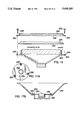
- FIG. 2 is a cross-sectional view of the drum of FIG. 1;
- FIG. 3 is a cross-sectional view of an alternate embodiment of the drum of this invention.
- FIGS. 4A and 4B are diagrammatic views showing alternate embodiments of the invention using microphones
- FIG. 5 is an exploded cross-sectional view of still another alternate embodiment of the drum of this invention.
- FIGS. 6A and 6B are partial plan and elevation diagrammatic views, respectively, of another embodiment of the invention using an electromagnetic transducer and a damping pad;
- FIG. 7 is a fragmentary elevation view partially in section of an alternate embodiment of the invention using an electromagnetic pickup secured to the drum rim;
- FIG. 8 is a diagrammatic sectional view of another embodiment of the invention.
- FIG. 9 is a diagrammatic representation of another embodiment of the invention with the drum head struck by a foot-operated beater
- FIG. 10 is a diagrammatic representation of another embodiment of the foot-operated practice system according to the invention.
- FIG. 11 is an exploded cross-sectional view of an alternate embodiment of the invention using an air spring and an electret microphone
- FIG. 12 is an exploded cross-sectional view of an alternate embodiment of the invention using an air spring and a dynamic microphone
- FIG. 13 is an exploded cross-sectional view of an alternate embodiment of the invention using a tunable drum head
- FIG. 14 shows four frequency response curves for dynamic microphone assemblies used in conjunction with the invention.
- FIG. 15 is a sound power level frequency response curve of a drum according to the invention using a microphone having the frequency response curve shown in curve 1 of FIG. 14;
- FIG. 16 is a frequency response curve for an active equalizer used in conjunction with the invention.
- FIGS. 17A and 17B are plan and cross-sectional diagrammatic views, respectively, showing an isolation mounting for the transducer of the invention.
- FIG. 18 is an exploded cross-sectional view of an alternate embodiment of the invention using a loudspeaker.
- FIG. 19 is a cross-sectional view of an alternate embodiment of the invention using an enclosed microphone in pressure communication with the interior of a conventional acoustic drum.
- drum 10 includes a circular drum head 12 mounted over a cylindrically annular drum shell 16.
- Drum head 12 has an outside surface 12A and an inside surface 12B (FIG. 2).
- Annular drum rim 14 of L-shaped cross-section embraces and maintains in tension drum head 12. Threaded lugs 18 pass through holes in rim 14 and screw into mounts 20 attached to shell 16.
- Driver 24 supports shell 16.
- L-shaped brackets 28 and bolts 30 connect driver 24 to shell 16 adjacent to bolts 32 which interconnect shell 16 and mounts 20.
- Driver 24 has an outer cone 42 and inner cone 44.
- the inside surface 12B of drum head 12 is connected to the annular outer rim of outer cone 42 by gel sheet 50.
- the diameter of drum head 12 is about equal to the diameter of outer cone 42 at the rim edge plus twice the wall thickness of shell 16.
- Gel sheet 50 may have adhesive on both surfaces.
- Component driver 40 is mounted on base 26, which includes magnet 56 and voice coil 58 carried by a lower central portion of component driver 40.
- Voice coil 58 is connected by electrical leads 62 to an electronic triggering interface known as a MIDI, musical instrument digital interface.
- Magnet assembly 56 is connected to basket 24A and carries voice coil 58 connected to inner cone 44. Leads 62 connect voice coil 58 to MIDI 60 to provide a signal on line 64 characteristic of the impact on drum head 12.
- base 90 is contained within drum shell 80.
- Magnet 70 is contained within voice coil 76, and is supported by flanges 72.
- the bottom 74 of drum shell 80 is made of plastic or similar material.
- Lead wires 92 are connected to single speaker cone 78.
- Drum head 88 and gel sheet 86 are connected to drum rim 84 by threaded lugs 82.
- gel sheet 100 is above drum head 102.
- Microphone 104 is connected to cone 106.
- Microphone 104 is an electret microphone which is used in place of the magnets and voice coils of the previously described embodiments.
- FIG. 4B there is shown a diagrammatic view of an alternate embodiment with microphone 110 displaced from gel sheet 100 and drum head 102.
- hoop 120 is shown apart from drum head 124 and gel sheet 122.
- Paper cone 132 is connected to metal foil 130.
- Shell 126 contains inductor 128 within it.
- Inductor 128 includes a magnet.
- the hoop assembly is placed on the drum head assembly, which is placed on shell 126.
- Metal foil 130 vibrates and varies the inductance of inductor 128 to provide an output signal.
- Drum head 131 carries a damping pad 132 secured to drum head 131 by adhesive tape 133 having adhesive on both sides.
- the output of electromagnetic transducer 134 is coupled by line 135 to output jack 136.
- a metal ribbon of ferromagnetic material 136 may be arranged as shown connected at 137 and biased by spring 138 to vary the inductance of electromagnetic transducer 134 in response to drum head 131 being struck.
- Drum head 141 contacts drum rim 142 which carries electromagnetic pickup 143 that senses vibrations of drum rim 142 to furnish an output voltage representative of the force upon drum head 141.
- Transducer 154 provides an output signal to output jack 155 over line 156 that is linear with respect to drum head velocity.
- FIG. 9 there is shown another embodiment of the invention in which the plane of the drum head 161 is in the vertical plane with drum 162 supported by stand 163. Foot-operated beater 164 strikes drum head 161.
- FIG. 10 there is shown a diagrammatic view partially in section of another embodiment of the invention using a foot-operated beater 171 that strikes gel or foam pad 172 backed by metal foil 173 of ferromagnetic material separated from coil 174 by air gap 175.
- frusto-conical baskets 200, 202 define interior frusto-conical air plenums.
- Pretuned drum heads 204, 206 are each fixed within the radially inner region of a cylindrical drum head retainer 208, 210.
- the diameter of the drum heads 204, 206 (and therefore the inner diameter of the drum head retainers 208, 210) approximately equals the large diameter of the basket, plus two times the width of an annular flange 212, 214 encircling the large-diameter end of each basket 200, 202.
- a gasket 216, 217 is positioned between the outer circumferential region of each drum head 204, 206 and flange 212,214.
- Each drum head/retainer assembly attaches to flange 212, 214 using equally circumferentially spaced clips 218, 219.
- Positioning clips 218,219 and tightening the associated screws 220, 221 forces the outer circumferential region of each drum head 204, 206 against its associated gasket 216, 217, forming an airtight seal.
- either a removable 0.060" natural rubber sheet 222, 223 can be attached to the outer surface of each drum head 208, 210, and/or polyester filler 224, 225 can be placed in the frusto-conical air plenums.
- the drum can be fitted with a tunable head.
- a hoop 228 of L-shaped cross-section engages a flange 230 encircling the outer circumference of a drum head 232.
- Holes 234 pass through a flange portion 236 of hoop 228 at regularly spaced circumferential intervals.
- Tension rods 238 inserted through these hoop holes 234 engage mating holes 240 in a flange 242 of a basket 244. Only the distal portion of each tension rod 238 is threaded. Applying different torques to the tension rods 238 varies the loading around the circumference of the drum head 232, changing the frequency characteristics of the instrument.
- a back wall 246 encloses the small-diameter end 248 of basket 200.
- An orifice plate 250 located within the interior of the basket 200 and oriented parallel to the drum head 204 defines an orifice 252 concentric with the axis of the basket 200.
- An electret microphone component driver 254 is located concentric with orifice 252.
- a cap 256 encloses the portion of electret microphone component driver 254 disposed closest to the back wall 246 of basket 200.
- the input leads 258 of electret microphone 254 connects to a battery 260, and the output leads 262 to a MIDI (not shown).
- a dynamic microphone component driver 270 is located concentric with orifice 272 in orifice plate 266.
- Dynamic microphone 270 available from JEMA, has been modified by increasing the number of turns in the voice coil (not shown) to raise the impedance to 600 ohms.
- the output leads 274 from this voice coil connect to a step-up transformer 276 having a ratio between 1:8 and 1:6.
- Step-up transformer 276 has a generally flat frequency response between 20 Hz and 10 kHz.
- the outputs leads 278 from transformer 276 connect to a MIDI (not shown).
- the frequency response of dynamic microphone 270 is shown in curve 1 of FIG. 14. As shown, dynamic microphone 270 attenuates frequencies below about 60 Hz. These frequency response characteristics make dynamic microphone 270 suitable for use with drum heads 6", 8", 10", and 12" in diameter. Using dynamic microphone 270 in a drum having an 8" diameter drum head results in the sound power level (SPL) frequency response curve shown in FIG. 15. If output leads 278 of transformer 276 are connected to a MIDI designed to accept 60k ohm impedance, dynamic microphones having the frequency responses shown in curves 2, 3, and 4 of FIG. 14 could instead be used with drum heads 10", 12", and 14" in diameter, respectively. Additionally or alternatively, the output of a dynamic microphone could be filtered using one or a series of high- and/or band-pass filters (not shown) in order to achieve the desired frequency response.
- SPL sound power level
- the output of a microphone could be connected to an active equalizer (not shown) that boosts frequency in accordance with the frequency response curve shown in FIG. 16. As shown, the SPL of the boost provided by the active equalizer increases generally proportionally with frequency.
- FIGS. 17A and 17B there are shown diagrammatic plan and cross-sectional views, respectively, of an isolation mount for the orifice plate 250 shown in FIG. 11.
- Grommets 280 are inserted into holes provided at equal circumferential intervals around the outer circumference of orifice plate 250. For example, as shown in FIG. 17A these holes are spaced at 120 degree intervals, such that they define the corners of an equilateral triangle.
- the grommets 280 are constructed of C-1000 material, available from E-A-R Specialty Composites. Any grommet having a low durometer and load capacity and a resonant frequency below about 30 Hz when loaded to 5% compression is also suitable for mounting and isolation purposes.
- the orifice plate 250 and electret microphone component driver 254 assembly is installed by bolting it to a shoulder region 282 of basket 200, such that the grommets 280 contact directly this shoulder region 282.
- a similar isolation mount (not shown) is used to attach the orifice plate 266 shown in FIG. 12 to basket 202.
- FIG. 18 there is shown an exploded cross-sectional view of another embodiment of the invention.
- This embodiment is similar in configuration to the embodiments shown in FIGS. 11 and 12, except that a basket 284 houses a loudspeaker cone 286, and there is no orifice plate.
- the large-diameter portion of the cone 286 contacts directly the outer circumferential region of a drum head 288. Striking drum head 288 vibrates cone 286 to generate an output signal.
- either a removable 0.060" natural rubber sheet 290 can be attached to the outer surface of the drum head 288, and/or polyester filler 292 can be placed within the interior of cone 286.
- FIG. 19 there is shown a cross-sectional view of another embodiment of the invention.
- a microphone 294 is located within a rubber housing 296.
- One portion of the housing forms an annular rubber plug 298, sized to be inserted snugly into an air vent 300 in the shell 302 of a conventional acoustic drum.
- a pressure equalization port 304 located in the housing 296 vents the back side of the microphone 294 to atmosphere. Striking the drum causes the head to oscillate, which in turn causes the pressure in the drum interior to fluctuate. The resulting pressure differential across the microphone diaphragm 306 causes it to vibrate and generate an output signal.
- the invention has a number of advantages. Striking the drum head provides an output signal representative of the force signal applied to the drum head that may be reproduced through an amplifying and transducing system to provide a sound accurately corresponding to the sound produced by an acoustic drum receiving the same impact.
- An advantage of the particular structural arrangement is that a musician striking drum head 12 perceives substantially the same feel on the drum sticks perceived when striking an acoustic drum.
- MIDI 60 receives the voltage from the component driver and converts the voltage to an output signal 64 recognizable to instruments used with the MIDI.
- a drum according to the invention also attenuates noise in the component driver output signal resulting from both "double triggering" effects and extraneous vibration. Double triggering occurs when spurious vibrations remaining after the head is struck continue to trigger the component driver, which results in a chain of repetitive sounds. Extraneous vibration is an issue both during live performances, where volume levels are often quite high, and in the studio, where multiple triggers are often spaced closely enough to cause cross-talk problems.
Landscapes
- Physics & Mathematics (AREA)
- Engineering & Computer Science (AREA)
- Acoustics & Sound (AREA)
- Multimedia (AREA)
- Electrophonic Musical Instruments (AREA)
Abstract
Description
Claims (50)
Priority Applications (1)
Application Number | Priority Date | Filing Date | Title |
---|---|---|---|
US08/132,518 US5430245A (en) | 1993-01-14 | 1993-10-06 | Electroacoustical drum |
Applications Claiming Priority (2)
Application Number | Priority Date | Filing Date | Title |
---|---|---|---|
US471293A | 1993-01-14 | 1993-01-14 | |
US08/132,518 US5430245A (en) | 1993-01-14 | 1993-10-06 | Electroacoustical drum |
Related Parent Applications (1)
Application Number | Title | Priority Date | Filing Date |
---|---|---|---|
US471293A Continuation-In-Part | 1993-01-14 | 1993-01-14 |
Publications (1)
Publication Number | Publication Date |
---|---|
US5430245A true US5430245A (en) | 1995-07-04 |
Family
ID=21712157
Family Applications (1)
Application Number | Title | Priority Date | Filing Date |
---|---|---|---|
US08/132,518 Expired - Fee Related US5430245A (en) | 1993-01-14 | 1993-10-06 | Electroacoustical drum |
Country Status (1)
Country | Link |
---|---|
US (1) | US5430245A (en) |
Cited By (26)
Publication number | Priority date | Publication date | Assignee | Title |
---|---|---|---|---|
US5585581A (en) * | 1992-06-23 | 1996-12-17 | Rtom Corporation | Gel drumhead transducing |
US5602354A (en) * | 1995-03-02 | 1997-02-11 | Martin; Thomas E. | Acoustical rhythm board |
US6121528A (en) * | 1999-01-27 | 2000-09-19 | May; Randall L. | Electroacoustically amplified drum and mounting bracket |
US20040211310A1 (en) * | 2003-04-25 | 2004-10-28 | Takashi Hagiwara | Sound pickup device for percussion instrument |
US20050022655A1 (en) * | 2003-07-28 | 2005-02-03 | Wise Johnathan R. | Real drum trigger monitor and amplified tone module |
US20070189553A1 (en) * | 2006-02-10 | 2007-08-16 | Holden Albert J Iii | Cylindrically shaped stage monitor |
US20070234886A1 (en) * | 2006-03-20 | 2007-10-11 | Roland Corporation | Electronic percussion instrument |
US7282633B1 (en) * | 2004-03-18 | 2007-10-16 | Coolidge Curtis J | Sound augmentation system and method for a drum |
US20070295189A1 (en) * | 2006-06-23 | 2007-12-27 | Jeffery Kelly | Stabilizing holder for sensory device |
US7408109B1 (en) | 2004-08-02 | 2008-08-05 | Paul John Freitas | Capacitive electric musical instrument vibration transducer |
US7560632B1 (en) | 2006-07-17 | 2009-07-14 | Lanzel Kenneth W | Bass drum with compliant resonant head |
US20090258686A1 (en) * | 2008-04-15 | 2009-10-15 | Mccauley Jack J | System and method for playing a music video game with a drum system game controller |
US7657051B1 (en) | 2005-05-05 | 2010-02-02 | Buckanear Productions, L.L.C. | Bass drum speaker |
US20100031806A1 (en) * | 2008-08-05 | 2010-02-11 | Gaynier David A | Electroacoustic Transducer System |
US20100107858A1 (en) * | 2008-10-30 | 2010-05-06 | Peavey Electronics Corporation | Electromechanical servo assisted drum |
US20110265634A1 (en) * | 2010-04-30 | 2011-11-03 | Joseph Licalzi | Guitar Speaker Drum and Rack System |
US20150179154A1 (en) * | 2013-12-23 | 2015-06-25 | Pearl Musical Instrument Co. | Removable electronic drum head and hoop for acoustic drum |
US20160140945A1 (en) * | 2013-06-21 | 2016-05-19 | Parsek Lab S.R.L. | Electronic Musical Instrument Percussion System with Electromagnetic Sensor |
US9378714B1 (en) * | 2015-02-10 | 2016-06-28 | Kevin L. Baldwin, Sr. | Electronic drum |
US20160223199A1 (en) * | 2013-02-21 | 2016-08-04 | Patrice Emma Morris | Birthday candle blow horn apparatus and method thereof |
US9672802B2 (en) * | 2015-02-04 | 2017-06-06 | John MUZZIO | Electronic drums |
US9761212B2 (en) | 2015-01-05 | 2017-09-12 | Rare Earth Dynamics, Inc. | Magnetically secured instrument trigger |
US9875732B2 (en) | 2015-01-05 | 2018-01-23 | Stephen Suitor | Handheld electronic musical percussion instrument |
US10096309B2 (en) | 2015-01-05 | 2018-10-09 | Rare Earth Dynamics, Inc. | Magnetically secured instrument trigger |
US10192534B2 (en) * | 2017-05-11 | 2019-01-29 | Yamaha Corporation | Percussion instrument |
US11335310B2 (en) | 2018-06-18 | 2022-05-17 | Rare Earth Dynamics, Inc. | Instrument trigger and instrument trigger mounting systems and methods |
Citations (15)
Publication number | Priority date | Publication date | Assignee | Title |
---|---|---|---|---|
US3509264A (en) * | 1967-12-29 | 1970-04-28 | Allen J Green | Electric drum or other percussion instrument |
US3553339A (en) * | 1967-12-11 | 1971-01-05 | Richard L Dominguez | Drum-like musical instruments with electrical pickups and circuitry |
CA964362A (en) * | 1973-03-29 | 1975-03-11 | Les Paul | Method of electrically reproducing music and an improved electrical pickup for practicing the same |
US3956959A (en) * | 1974-04-30 | 1976-05-18 | Sanyo Silicon Electronics Co., Ltd. | Electronic percussion instrument |
US4168646A (en) * | 1978-07-24 | 1979-09-25 | May Randall L | Electro-acoustically amplified drum |
US4201107A (en) * | 1978-06-19 | 1980-05-06 | Barber Harold G Jr | Audio power percussion pickups |
US4242937A (en) * | 1979-02-08 | 1981-01-06 | Pozar Cleve F | Pickup assembly for percussion instrument |
US4416181A (en) * | 1981-04-03 | 1983-11-22 | Remo, Inc. | Pretuned head for drum or the like |
US4669349A (en) * | 1984-07-05 | 1987-06-02 | Nippon Gakki Seizo Kabushiki Kaisha | Electronic drum having a closed air space |
US4837836A (en) * | 1982-09-30 | 1989-06-06 | Barcus Lester M | Microphone pickup system |
WO1990003639A1 (en) * | 1988-09-20 | 1990-04-05 | Bradley Roy Clark | Transducer device for musical instruments |
US4947725A (en) * | 1986-06-30 | 1990-08-14 | Casio Computer Co., Ltd. | Electronic drum |
US4984498A (en) * | 1987-10-26 | 1991-01-15 | Lawrence Fishman | Percussion transducer |
US5042356A (en) * | 1989-07-06 | 1991-08-27 | Karch Jeffrey M | Kit for converting a conventional drum into an electronically triggered drum |
US5056403A (en) * | 1986-10-14 | 1991-10-15 | Yamaha Corporation | Electronic drum with vibration isolating head |
-
1993
- 1993-10-06 US US08/132,518 patent/US5430245A/en not_active Expired - Fee Related
Patent Citations (15)
Publication number | Priority date | Publication date | Assignee | Title |
---|---|---|---|---|
US3553339A (en) * | 1967-12-11 | 1971-01-05 | Richard L Dominguez | Drum-like musical instruments with electrical pickups and circuitry |
US3509264A (en) * | 1967-12-29 | 1970-04-28 | Allen J Green | Electric drum or other percussion instrument |
CA964362A (en) * | 1973-03-29 | 1975-03-11 | Les Paul | Method of electrically reproducing music and an improved electrical pickup for practicing the same |
US3956959A (en) * | 1974-04-30 | 1976-05-18 | Sanyo Silicon Electronics Co., Ltd. | Electronic percussion instrument |
US4201107A (en) * | 1978-06-19 | 1980-05-06 | Barber Harold G Jr | Audio power percussion pickups |
US4168646A (en) * | 1978-07-24 | 1979-09-25 | May Randall L | Electro-acoustically amplified drum |
US4242937A (en) * | 1979-02-08 | 1981-01-06 | Pozar Cleve F | Pickup assembly for percussion instrument |
US4416181A (en) * | 1981-04-03 | 1983-11-22 | Remo, Inc. | Pretuned head for drum or the like |
US4837836A (en) * | 1982-09-30 | 1989-06-06 | Barcus Lester M | Microphone pickup system |
US4669349A (en) * | 1984-07-05 | 1987-06-02 | Nippon Gakki Seizo Kabushiki Kaisha | Electronic drum having a closed air space |
US4947725A (en) * | 1986-06-30 | 1990-08-14 | Casio Computer Co., Ltd. | Electronic drum |
US5056403A (en) * | 1986-10-14 | 1991-10-15 | Yamaha Corporation | Electronic drum with vibration isolating head |
US4984498A (en) * | 1987-10-26 | 1991-01-15 | Lawrence Fishman | Percussion transducer |
WO1990003639A1 (en) * | 1988-09-20 | 1990-04-05 | Bradley Roy Clark | Transducer device for musical instruments |
US5042356A (en) * | 1989-07-06 | 1991-08-27 | Karch Jeffrey M | Kit for converting a conventional drum into an electronically triggered drum |
Cited By (41)
Publication number | Priority date | Publication date | Assignee | Title |
---|---|---|---|---|
US5585581A (en) * | 1992-06-23 | 1996-12-17 | Rtom Corporation | Gel drumhead transducing |
US5602354A (en) * | 1995-03-02 | 1997-02-11 | Martin; Thomas E. | Acoustical rhythm board |
US6121528A (en) * | 1999-01-27 | 2000-09-19 | May; Randall L. | Electroacoustically amplified drum and mounting bracket |
US20040211310A1 (en) * | 2003-04-25 | 2004-10-28 | Takashi Hagiwara | Sound pickup device for percussion instrument |
JP2004325908A (en) * | 2003-04-25 | 2004-11-18 | Yamaha Corp | Sound collecting device of percussion instrument |
DE102004019848B4 (en) * | 2003-04-25 | 2006-10-05 | Yamaha Corp., Hamamatsu | Pickup device for percussion instrument |
US7256342B2 (en) * | 2003-04-25 | 2007-08-14 | Yamaha Corporation | Sound pickup device for percussion instrument |
WO2005017874A3 (en) * | 2003-07-28 | 2009-08-27 | Wise Johnathan R | Real drum trigger monitor and tone module |
US20050022655A1 (en) * | 2003-07-28 | 2005-02-03 | Wise Johnathan R. | Real drum trigger monitor and amplified tone module |
WO2005017874A2 (en) * | 2003-07-28 | 2005-02-24 | Wise Johnathan R | Real drum trigger monitor and tone module |
US6982376B2 (en) * | 2003-07-28 | 2006-01-03 | Wise Johnathan R | Real drum trigger monitor and amplified tone module |
US7282633B1 (en) * | 2004-03-18 | 2007-10-16 | Coolidge Curtis J | Sound augmentation system and method for a drum |
US7408109B1 (en) | 2004-08-02 | 2008-08-05 | Paul John Freitas | Capacitive electric musical instrument vibration transducer |
US7657051B1 (en) | 2005-05-05 | 2010-02-02 | Buckanear Productions, L.L.C. | Bass drum speaker |
US20070189553A1 (en) * | 2006-02-10 | 2007-08-16 | Holden Albert J Iii | Cylindrically shaped stage monitor |
US20070234886A1 (en) * | 2006-03-20 | 2007-10-11 | Roland Corporation | Electronic percussion instrument |
US7612273B2 (en) * | 2006-03-20 | 2009-11-03 | Roland Corporation | Electronic percussion instrument |
US20070295189A1 (en) * | 2006-06-23 | 2007-12-27 | Jeffery Kelly | Stabilizing holder for sensory device |
US7723596B2 (en) | 2006-06-23 | 2010-05-25 | Jeffery Kelly | Stabilizing holder for sensory device |
US7560632B1 (en) | 2006-07-17 | 2009-07-14 | Lanzel Kenneth W | Bass drum with compliant resonant head |
US8317614B2 (en) | 2008-04-15 | 2012-11-27 | Activision Publishing, Inc. | System and method for playing a music video game with a drum system game controller |
US20090258686A1 (en) * | 2008-04-15 | 2009-10-15 | Mccauley Jack J | System and method for playing a music video game with a drum system game controller |
US9452358B2 (en) | 2008-04-15 | 2016-09-27 | Activision Publishing, Inc. | System and method for playing a music video game with a drum system game controller |
US8777747B2 (en) | 2008-04-15 | 2014-07-15 | Activision Publishing, Inc. | System and method for playing a music video game with a drum system game controller |
US20100031806A1 (en) * | 2008-08-05 | 2010-02-11 | Gaynier David A | Electroacoustic Transducer System |
US8003878B2 (en) * | 2008-08-05 | 2011-08-23 | Gaynier David A | Electroacoustic transducer system |
US20100107858A1 (en) * | 2008-10-30 | 2010-05-06 | Peavey Electronics Corporation | Electromechanical servo assisted drum |
US8071871B2 (en) | 2008-10-30 | 2011-12-06 | Peavey Electronics Corporation | Electromechanical servo assisted drum |
US20110265634A1 (en) * | 2010-04-30 | 2011-11-03 | Joseph Licalzi | Guitar Speaker Drum and Rack System |
US20160223199A1 (en) * | 2013-02-21 | 2016-08-04 | Patrice Emma Morris | Birthday candle blow horn apparatus and method thereof |
US20160140945A1 (en) * | 2013-06-21 | 2016-05-19 | Parsek Lab S.R.L. | Electronic Musical Instrument Percussion System with Electromagnetic Sensor |
US9390697B2 (en) * | 2013-12-23 | 2016-07-12 | Pearl Musical Instrument Co. | Removable electronic drum head and hoop for acoustic drum |
US20150179154A1 (en) * | 2013-12-23 | 2015-06-25 | Pearl Musical Instrument Co. | Removable electronic drum head and hoop for acoustic drum |
US9761212B2 (en) | 2015-01-05 | 2017-09-12 | Rare Earth Dynamics, Inc. | Magnetically secured instrument trigger |
US9875732B2 (en) | 2015-01-05 | 2018-01-23 | Stephen Suitor | Handheld electronic musical percussion instrument |
US10096309B2 (en) | 2015-01-05 | 2018-10-09 | Rare Earth Dynamics, Inc. | Magnetically secured instrument trigger |
US9672802B2 (en) * | 2015-02-04 | 2017-06-06 | John MUZZIO | Electronic drums |
US9378714B1 (en) * | 2015-02-10 | 2016-06-28 | Kevin L. Baldwin, Sr. | Electronic drum |
US9741324B2 (en) | 2015-02-10 | 2017-08-22 | Kevin L. Baldwin, Sr. | Electronic drum |
US10192534B2 (en) * | 2017-05-11 | 2019-01-29 | Yamaha Corporation | Percussion instrument |
US11335310B2 (en) | 2018-06-18 | 2022-05-17 | Rare Earth Dynamics, Inc. | Instrument trigger and instrument trigger mounting systems and methods |
Similar Documents
Publication | Publication Date | Title |
---|---|---|
US5430245A (en) | Electroacoustical drum | |
CN210225743U (en) | Single-magnetic double-sound-path coaxial loudspeaker | |
CA1219055A (en) | Multi-driver loudspeaker | |
US4756382A (en) | Loudspeaker having enhanced response at bass frequencies | |
US4239945A (en) | Sealed headphone | |
JP3193281U (en) | Piezoelectric speaker | |
US6115475A (en) | Capacitor-less crossover network for electro-acoustic loudspeakers | |
US10621965B2 (en) | Acoustic apparatus | |
US20060215870A1 (en) | Low profile speaker and system | |
JP2004325908A (en) | Sound collecting device of percussion instrument | |
WO2016112038A1 (en) | Magnetically secured instrument trigger | |
US20100031806A1 (en) | Electroacoustic Transducer System | |
US8160291B2 (en) | Voice coil and speaker | |
US6431308B1 (en) | High fidelity small omnidirectional loudspeaker | |
US20120321123A1 (en) | Compact coaxial crossover-free loudspeaker | |
GB2306273A (en) | Loudspeaker enclosure has the shape of a stringed musical instrument | |
US4466505A (en) | Sound reproducing combination | |
US4598789A (en) | Sound reproducing | |
US6445803B1 (en) | Speaker | |
US7319772B2 (en) | Speaker device for improving mid/high-range frequencies | |
JP3896675B2 (en) | Speaker device | |
CA1204498A (en) | Multi-driver loudspeaker | |
JPH02170795A (en) | Panel type loudspeaker | |
KR100676422B1 (en) | A multi-way slim panel speaker system with multi-point drive | |
JPH0974599A (en) | Speaker device |
Legal Events
Date | Code | Title | Description |
---|---|---|---|
AS | Assignment |
Owner name: RTOM CORPORATION, NEW JERSEY Free format text: ASSIGNMENT OF ASSIGNORS INTEREST;ASSIGNOR:ROGERS, THOMAS P.;REEL/FRAME:007268/0270 Effective date: 19931109 |
|
AS | Assignment |
Owner name: ALESIS CORPORATION, CALIFORNIA Free format text: SECURITY AGREEMENT;ASSIGNOR:RTOM CORPORATION;REEL/FRAME:008933/0909 Effective date: 19971015 |
|
REMI | Maintenance fee reminder mailed | ||
FPAY | Fee payment |
Year of fee payment: 4 |
|
SULP | Surcharge for late payment | ||
FPAY | Fee payment |
Year of fee payment: 8 |
|
REMI | Maintenance fee reminder mailed | ||
LAPS | Lapse for failure to pay maintenance fees | ||
STCH | Information on status: patent discontinuation |
Free format text: PATENT EXPIRED DUE TO NONPAYMENT OF MAINTENANCE FEES UNDER 37 CFR 1.362 |
|
FP | Lapsed due to failure to pay maintenance fee |
Effective date: 20070704 |