US5413767A - Mechanically stabilized heating catalyst configuration - Google Patents
Mechanically stabilized heating catalyst configuration Download PDFInfo
- Publication number
- US5413767A US5413767A US08/175,251 US17525193A US5413767A US 5413767 A US5413767 A US 5413767A US 17525193 A US17525193 A US 17525193A US 5413767 A US5413767 A US 5413767A
- Authority
- US
- United States
- Prior art keywords
- honeycomb body
- honeycomb
- support elements
- bodies
- heatable
- Prior art date
- Legal status (The legal status is an assumption and is not a legal conclusion. Google has not performed a legal analysis and makes no representation as to the accuracy of the status listed.)
- Expired - Lifetime
Links
Images

Classifications
-
- F—MECHANICAL ENGINEERING; LIGHTING; HEATING; WEAPONS; BLASTING
- F01—MACHINES OR ENGINES IN GENERAL; ENGINE PLANTS IN GENERAL; STEAM ENGINES
- F01N—GAS-FLOW SILENCERS OR EXHAUST APPARATUS FOR MACHINES OR ENGINES IN GENERAL; GAS-FLOW SILENCERS OR EXHAUST APPARATUS FOR INTERNAL COMBUSTION ENGINES
- F01N3/00—Exhaust or silencing apparatus having means for purifying, rendering innocuous, or otherwise treating exhaust
- F01N3/08—Exhaust or silencing apparatus having means for purifying, rendering innocuous, or otherwise treating exhaust for rendering innocuous
- F01N3/10—Exhaust or silencing apparatus having means for purifying, rendering innocuous, or otherwise treating exhaust for rendering innocuous by thermal or catalytic conversion of noxious components of exhaust
- F01N3/24—Exhaust or silencing apparatus having means for purifying, rendering innocuous, or otherwise treating exhaust for rendering innocuous by thermal or catalytic conversion of noxious components of exhaust characterised by constructional aspects of converting apparatus
- F01N3/28—Construction of catalytic reactors
- F01N3/2803—Construction of catalytic reactors characterised by structure, by material or by manufacturing of catalyst support
- F01N3/2807—Metal other than sintered metal
- F01N3/281—Metallic honeycomb monoliths made of stacked or rolled sheets, foils or plates
-
- F—MECHANICAL ENGINEERING; LIGHTING; HEATING; WEAPONS; BLASTING
- F01—MACHINES OR ENGINES IN GENERAL; ENGINE PLANTS IN GENERAL; STEAM ENGINES
- F01N—GAS-FLOW SILENCERS OR EXHAUST APPARATUS FOR MACHINES OR ENGINES IN GENERAL; GAS-FLOW SILENCERS OR EXHAUST APPARATUS FOR INTERNAL COMBUSTION ENGINES
- F01N13/00—Exhaust or silencing apparatus characterised by constructional features ; Exhaust or silencing apparatus, or parts thereof, having pertinent characteristics not provided for in, or of interest apart from, groups F01N1/00 - F01N5/00, F01N9/00, F01N11/00
- F01N13/009—Exhaust or silencing apparatus characterised by constructional features ; Exhaust or silencing apparatus, or parts thereof, having pertinent characteristics not provided for in, or of interest apart from, groups F01N1/00 - F01N5/00, F01N9/00, F01N11/00 having two or more separate purifying devices arranged in series
- F01N13/0097—Exhaust or silencing apparatus characterised by constructional features ; Exhaust or silencing apparatus, or parts thereof, having pertinent characteristics not provided for in, or of interest apart from, groups F01N1/00 - F01N5/00, F01N9/00, F01N11/00 having two or more separate purifying devices arranged in series the purifying devices are arranged in a single housing
-
- F—MECHANICAL ENGINEERING; LIGHTING; HEATING; WEAPONS; BLASTING
- F01—MACHINES OR ENGINES IN GENERAL; ENGINE PLANTS IN GENERAL; STEAM ENGINES
- F01N—GAS-FLOW SILENCERS OR EXHAUST APPARATUS FOR MACHINES OR ENGINES IN GENERAL; GAS-FLOW SILENCERS OR EXHAUST APPARATUS FOR INTERNAL COMBUSTION ENGINES
- F01N3/00—Exhaust or silencing apparatus having means for purifying, rendering innocuous, or otherwise treating exhaust
- F01N3/08—Exhaust or silencing apparatus having means for purifying, rendering innocuous, or otherwise treating exhaust for rendering innocuous
- F01N3/10—Exhaust or silencing apparatus having means for purifying, rendering innocuous, or otherwise treating exhaust for rendering innocuous by thermal or catalytic conversion of noxious components of exhaust
- F01N3/18—Exhaust or silencing apparatus having means for purifying, rendering innocuous, or otherwise treating exhaust for rendering innocuous by thermal or catalytic conversion of noxious components of exhaust characterised by methods of operation; Control
- F01N3/20—Exhaust or silencing apparatus having means for purifying, rendering innocuous, or otherwise treating exhaust for rendering innocuous by thermal or catalytic conversion of noxious components of exhaust characterised by methods of operation; Control specially adapted for catalytic conversion ; Methods of operation or control of catalytic converters
- F01N3/2006—Periodically heating or cooling catalytic reactors, e.g. at cold starting or overheating
- F01N3/2013—Periodically heating or cooling catalytic reactors, e.g. at cold starting or overheating using electric or magnetic heating means
- F01N3/2026—Periodically heating or cooling catalytic reactors, e.g. at cold starting or overheating using electric or magnetic heating means directly electrifying the catalyst substrate, i.e. heating the electrically conductive catalyst substrate by joule effect
-
- F—MECHANICAL ENGINEERING; LIGHTING; HEATING; WEAPONS; BLASTING
- F01—MACHINES OR ENGINES IN GENERAL; ENGINE PLANTS IN GENERAL; STEAM ENGINES
- F01N—GAS-FLOW SILENCERS OR EXHAUST APPARATUS FOR MACHINES OR ENGINES IN GENERAL; GAS-FLOW SILENCERS OR EXHAUST APPARATUS FOR INTERNAL COMBUSTION ENGINES
- F01N3/00—Exhaust or silencing apparatus having means for purifying, rendering innocuous, or otherwise treating exhaust
- F01N3/08—Exhaust or silencing apparatus having means for purifying, rendering innocuous, or otherwise treating exhaust for rendering innocuous
- F01N3/10—Exhaust or silencing apparatus having means for purifying, rendering innocuous, or otherwise treating exhaust for rendering innocuous by thermal or catalytic conversion of noxious components of exhaust
- F01N3/24—Exhaust or silencing apparatus having means for purifying, rendering innocuous, or otherwise treating exhaust for rendering innocuous by thermal or catalytic conversion of noxious components of exhaust characterised by constructional aspects of converting apparatus
- F01N3/28—Construction of catalytic reactors
- F01N3/2803—Construction of catalytic reactors characterised by structure, by material or by manufacturing of catalyst support
-
- F—MECHANICAL ENGINEERING; LIGHTING; HEATING; WEAPONS; BLASTING
- F01—MACHINES OR ENGINES IN GENERAL; ENGINE PLANTS IN GENERAL; STEAM ENGINES
- F01N—GAS-FLOW SILENCERS OR EXHAUST APPARATUS FOR MACHINES OR ENGINES IN GENERAL; GAS-FLOW SILENCERS OR EXHAUST APPARATUS FOR INTERNAL COMBUSTION ENGINES
- F01N3/00—Exhaust or silencing apparatus having means for purifying, rendering innocuous, or otherwise treating exhaust
- F01N3/08—Exhaust or silencing apparatus having means for purifying, rendering innocuous, or otherwise treating exhaust for rendering innocuous
- F01N3/10—Exhaust or silencing apparatus having means for purifying, rendering innocuous, or otherwise treating exhaust for rendering innocuous by thermal or catalytic conversion of noxious components of exhaust
- F01N3/24—Exhaust or silencing apparatus having means for purifying, rendering innocuous, or otherwise treating exhaust for rendering innocuous by thermal or catalytic conversion of noxious components of exhaust characterised by constructional aspects of converting apparatus
- F01N3/28—Construction of catalytic reactors
- F01N3/2839—Arrangements for mounting catalyst support in housing, e.g. with means for compensating thermal expansion or vibration
- F01N3/2842—Arrangements for mounting catalyst support in housing, e.g. with means for compensating thermal expansion or vibration specially adapted for monolithic supports, e.g. of honeycomb type
-
- F—MECHANICAL ENGINEERING; LIGHTING; HEATING; WEAPONS; BLASTING
- F02—COMBUSTION ENGINES; HOT-GAS OR COMBUSTION-PRODUCT ENGINE PLANTS
- F02B—INTERNAL-COMBUSTION PISTON ENGINES; COMBUSTION ENGINES IN GENERAL
- F02B1/00—Engines characterised by fuel-air mixture compression
- F02B1/02—Engines characterised by fuel-air mixture compression with positive ignition
- F02B1/04—Engines characterised by fuel-air mixture compression with positive ignition with fuel-air mixture admission into cylinder
-
- Y—GENERAL TAGGING OF NEW TECHNOLOGICAL DEVELOPMENTS; GENERAL TAGGING OF CROSS-SECTIONAL TECHNOLOGIES SPANNING OVER SEVERAL SECTIONS OF THE IPC; TECHNICAL SUBJECTS COVERED BY FORMER USPC CROSS-REFERENCE ART COLLECTIONS [XRACs] AND DIGESTS
- Y02—TECHNOLOGIES OR APPLICATIONS FOR MITIGATION OR ADAPTATION AGAINST CLIMATE CHANGE
- Y02T—CLIMATE CHANGE MITIGATION TECHNOLOGIES RELATED TO TRANSPORTATION
- Y02T10/00—Road transport of goods or passengers
- Y02T10/10—Internal combustion engine [ICE] based vehicles
- Y02T10/12—Improving ICE efficiencies
Definitions
- the invention relates to an apparatus for catalytic combustion of exhaust gases in an exhaust system, particularly for an exhaust system of an internal combustion engine, and preferably for Otto engines, having at least a first and a second honeycomb body through which a fluid can flow in succession, the honeycomb bodies each having a multiplicity of channels and at least one of the honeycomb bodies being heatable, and a plurality of support elements each having at least one end, the support elements extending between the first honeycomb body and the second honeycomb body, joining them mechanically, and protruding at least part way into the respective honeycomb body in the region of the at least one end.
- honeycomb body having a plurality of disks being braced against one another.
- the honeycomb body has at least two disks which are spaced apart from one another and disposed one after the other in terms of the flow direction of an exhaust gas, and each of them has channels.
- supports are provided by which the disks are joined together and braced against one another.
- Honeycomb bodies particularly those that are electrically heatable, are also known from Published International Application WO 92/18245; Published International Application WO 89/10471, corresponding to allowed U.S. application Ser. No. 07/604,199, filed, Oct. 25, 1990 and U.S. application Ser. No. 08/054,348, filed Apr. 27, 1993; Published International Application WO 93/20339; and Published International Application WO 92/00190, corresponding to U.S. application Ser. No. 08/101,455, filed, Aug. 2, 1993.
- a support element is firmly joined to the end surface of one honeycomb body, so that a free end of the support element protrudes into the other honeycomb body.
- suitable cross sections extend from a seat with play to a press-fit seat, and a certain elastic or plastic deformation of a honeycomb channel may also occur when the support elements are fitted into the honeycomb channels.
- the particular advantage of this apparatus is that it can be manufactured very easily.
- the support elements are preferably first secured to one of the honeycomb bodies. This can be done, for example, by brazing them on the end surface to an already existing load-bearing structure or, for instance, by introducing a support element during the process of winding up a honeycomb body from stacks of sheet-metal layers.
- the support elements then preferably protrude to the outside at one end surface, approximately parallel to a flow axis of the honeycomb body.
- a thus-prepared honeycomb body can then be secured to a second honeycomb body, by fitting the pro-truding support elements into individual honeycomb channels of the second honeycomb body, so that one end surface of each of the first and second honeycomb bodies face one another.
- the honeycomb bodies preferably do not touch one another then. It is advantageous if each honeycomb body is equipped with its own casing tube.
- the casing tubes are dimensioned in such a way that they can be thrust one inside the other, but they are provided with a stop to prevent the honeycomb bodies located in the casing tubes from touching when fitted together.
- An advantage of using one casing tube for each individual honeycomb body is that when the honeycomb bodies are joined together, the casing tubes assure secure guidance. In case of mass production it may be more advantageous to use one casing only for all honeycomb bodies.
- an insulating mount for the electrically heatable honeycomb body is provided.
- the apparatus according to the invention affords great flexibility in the production of exhaust gas catalytic converters having a heated disk.
- an arbitrary number of support elements can be provided, which are suitably distributed over the cross-sectional area of the configuration, to avoid vibration during all accelerations and at all frequencies that may be expected.
- the support elements may be distributed either statistically or systematically over the cross section.
- honeycomb bodies that are produced from corrugated layers of sheet metal such channels can be attained by providing that the corrugating rollers used for the production have one or more relatively large teeth.
- the diameter of the support elements can therefore be chosen within certain limits, regardless of the mean diameter of the channels of the honeycomb body. Moreover, the supports, especially if they are pointed at one or both ends, can also be driven into a honeycomb body, causing their plastic deformation. This provides greater freedom in terms of the shapes and cross-sectional areas of the support elements.
- the support elements are first inserted into the shorter honeycomb body, while extending over the entire axial length of this honeycomb body.
- the free ends of the support elements then protrude from one end surface, while when the two honeycomb bodies are put together, the other ends are hindered from displacement within the first honeycomb body from behind by a simple plate or the like, while the free ends of the pins are being thrust into the second honeycomb body.
- the at least the free ends of the support elements taper, and in particular are pointed in the form of a nail.
- the free ends of the support elements will always meet a channel of the second honeycomb body, and are possibly pressed very slightly to the side.
- the first honeycomb body when completely equipped with support elements, can therefore always be braced by the support elements on an arbitrary honeycomb body disposed behind it. This procedure is virtually equivalent to permanent nailing of a plurality of nails.
- the present invention is especially suitable for the mutual bracing of two honeycomb bodies with different mean channel cross sections.
- the first honeycomb body for instance, may have a low number of cells per unit of cross sectional area or vice versa, which is advantageous for electrically heatable honeycomb bodies, while the second honeycomb body may have a larger number of channels per unit of cross-sectional area.
- n of support elements meets the following relationship: ##EQU1## wherein mHK is the mass of the heatable honeycomb body (1); mSt is the mass of a support element (3); a is a maximum acceleration to be expected in the axial and/or radial direction of the apparatus; A is the load-bearing cross-sectional area; and ⁇ zul is the maximum allowable mechanical tension occurring in the operating temperature range.
- an electrically heatable honeycomb body has at least one electrically conductive path of a length P, which may be intertwined in a meandering or other fashion.
- the electrical insulation of this path from adjacent parts is carried out either by means of air gaps or by means of insulating intervening layers. In both cases, parts of the electrical path can vibrate, and support elements should therefore be disposed with a mean spacing 1 along the electrically conductive path.
- the heated honeycomb body is the first disk of the apparatus and has an axial length of from 5 to 30 mm, and preferably approximately 10 mm.
- the mass to be braced becomes less, so that the dimensioning and spacing of support elements should be performed in accordance with the above formulas.
- the support elements themselves preferably include metal pins, particularly in the manner of sheathed conductors. Such pins can be joined metal to metal, particularly by being brazed, without their being an electrical connection between the inner pin and the outer casing. Nevertheless, they bring about a mechanically very durable support.
- the present invention can be employed for mutually bracing the most varied types of honeycomb bodies.
- the honeycomb bodies being braced against one another are formed of metal or ceramic, are be made up of individual sheet-metal layers or extruded, and combinations are also possible.
- FIG. 1 is a diagrammatic, longitudinal-sectional view of a configuration according to the invention including a first heatable honeycomb body and a second honeycomb body serving as a carrier body;
- FIG. 2 is a cross-sectional view of the heatable honeycomb body of FIG. 1;
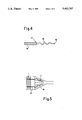
- FIG. 3 is a longitudinal-sectional view of a support element
- FIG. 4 is a longitudinal-sectional view of another embodiment of a support element.
- FIG. 5 is a longitudinal-sectional view of a configuration having one heatable honeycomb body and one conical honeycomb body.
- FIG. 1 there is seen a preferred exemplary embodiment of the invention in a diagrammatic longitudinal section, which shows only three of many support elements, for the sake of simplicity.
- An eletrically heatable first honeycomb body 1 is spaced apart from a second honeycomb body 2.
- the second honeycomb body 2 serves as a carrier.
- Support elements 3 interconnect the two honeycomb bodies 1 and 2 and brace the first honeycomb body 1, which has a stronger tendency to vibration, against the honeycomb body 2.
- the first honeycomb body 1 is secured in two half-shells 7, 8 in a manner which is known per se, by way of which electrical current is also delivered. These half-shells 7 and 8 are retained and electrically insulated in a casing 9.
- the second honeycomb body is also retained in a casing 12, and the two casings 9 and 12 are joined together to make a unit by joining techniques. It is also possible in principle to accommodate the configuration in a one-piece casing.
- the second honeycomb body 2 in the present exemplary embodiment has a slightly curved end surface oriented or facing toward the first honeycomb body 1, and as a result the bracing of the first honeycomb body 1 in the middle, where the tendency to vibration is the greatest, is reinforced, without infringement in the outer region of the spacing necessary for the electrical insulation of the half-shell 8.
- FIG. 2 is a diagrammatic cross section through the first honeycomb body 1.
- electrical power lines 10 and 11 are ducted in an electrically insulated fashion through the casing 9.
- the power lines or electrodes 10 and 11 supply the half-shells 7 and 8 with heating current.
- the first honeycomb body is a honeycomb body that is produced in a manner which is known per se from a stack of metal sheets that are intertwined in the form of an S.
- the support elements 3 are inserted into some of the channels of this honeycomb body and may be distributed statistically or symmetrically over the cross-sectional area. In particular, it is advantageous if these support elements are disposed at certain intervals, i.e.
- the support elements may be constructed in such a way that they can be inserted by one end into arbitrary channels of the first honeycomb body, and when the honeycomb bodies are put together can then be thrust into arbitrary channels of the second honeycomb body.
- honeycomb body has a relatively low number of channels per unit of cross-sectional area, while a following honeycomb body should have a larger number of channels per unit of cross-sectional area.
- the support elements in the region in which they rest in the first honeycomb body to be thicker than in the region is that can be thrust into the second honeycomb body.
- This also readily affords the possibility of constructing the support elements in such a way as to be electrically insulating, as will be described in detail in conjunction with FIGS. 3 and 4 below, in order to avoid electric circuits through the second honeycomb body in the event that that honeycomb body is also electrically conductive.
- FIG. 3 shows a longitudinal section through a support element 3 having a support element sheath 4 and a support pin 5.
- the support element sheath 4 and the support pin 5 can be joined together and simultaneously electrically insulated from one another by means of a ceramic insulating layer, as is known, for instance, for electrical sheathed conductors.
- the electrical insulation may be omitted if there is no need to fear an electrical short circuit because of the configuration of the pins or the electrical properties of the second honeycomb body. If the channel cross sections in the two honeycomb bodies to be joined together are approximately the same, then naturally a second support element sheath may be provided on the other end of the support pin 5, if an electrical insulation is desired. If not, a pin having the same diameter throughout may be used.
- the support elements have a support pin point 6, since when the parts are put together this point will always find a channel located approximately opposite it and can be thrust into a channel of the second honeycomb body, possibly becoming deformed in the process.
- FIG. 4 shows a further embodiment of a support element 13, which once again has a support element sheath 14 being electrically insulated from a support pin 15.
- the support pin 15 is serpentine or helical, and the amplitude of the corrugation or the diameter of the corrugation can be adapted to various channel cross sections of the honeycomb body into which this support pin is intended to be thrust.
- the support pin 15 it is naturally appropriate for the support pin 15 to have a support pin point 16 or a taper of the serpentine or helical coil.
- FIG. 5 shows an example of the many possible combinations permitted by the present invention.
- a first electrically heatable honeycomb body 1 is braced against a conical honeycomb body 18 by support pins 23. Since channels 17 of this conical honeycomb body 18 are also conical, a structure in accordance with FIG. 4 with a serpentine or helical coil, in which the amplitude or diameter decreases toward the point 16, is especially suitable for the support pins 23.
- the present invention is especially suitable for bracing relatively short heatable honeycomb bodies against following, more-stable honeycomb bodies, but is not limited to such exemplary embodiments. Due to the great versatility in terms of the selection of braces, no consideration need be taken of the mechanical stability or its natural resonance in constructing the electrically heatable honeycomb body, since vibration can be prevented by means of a suitable selection of the number and locations of support elements.
Applications Claiming Priority (2)
| Application Number | Priority Date | Filing Date | Title |
|---|---|---|---|
| DE9317050U DE9317050U1 (de) | 1993-11-08 | 1993-11-08 | Mechanisch stabilisierte Heizkatalysatoranordnung |
| DE9317050U | 1993-11-08 |
Publications (1)
| Publication Number | Publication Date |
|---|---|
| US5413767A true US5413767A (en) | 1995-05-09 |
Family
ID=6900430
Family Applications (1)
| Application Number | Title | Priority Date | Filing Date |
|---|---|---|---|
| US08/175,251 Expired - Lifetime US5413767A (en) | 1993-11-08 | 1993-12-27 | Mechanically stabilized heating catalyst configuration |
Country Status (2)
| Country | Link |
|---|---|
| US (1) | US5413767A (de) |
| DE (1) | DE9317050U1 (de) |
Cited By (20)
| Publication number | Priority date | Publication date | Assignee | Title |
|---|---|---|---|---|
| US5618462A (en) * | 1993-02-08 | 1997-04-08 | Emitec Gesellschaft Fuer Emissionstechnologie | Electrically insulating, gas-tight leadthrough for at least one electrical conductor through a metallic sheath |
| US5768889A (en) * | 1995-09-22 | 1998-06-23 | Emitec Gesellschaft Fuer Emissions-Technologie Mbh | Device for catalytically converting exhaust gases in an exhaust system |
| US5916530A (en) * | 1994-08-29 | 1999-06-29 | Emitec Gesellschaft Fuer Emissionstechnologie Mbh | Catalytic reactor |
| US5958347A (en) * | 1997-02-18 | 1999-09-28 | Precision Combustion, Inc. | Pre-converter mounting device |
| US6200538B1 (en) * | 1997-06-12 | 2001-03-13 | Emitec Gesellschaft Fuer Emissionstechnologie Mbh | Exhaust gas system suitable for retrofitting exhaust gas catalytic converters in motorcycles |
| US6274099B1 (en) * | 1994-10-21 | 2001-08-14 | Emitec Gesellschaft Fuer Emissionstechnologies Mbh | Device for catalytic conversion of exhaust gases in an exhaust system and process for manufacturing such a device |
| US20030003031A1 (en) * | 2000-01-10 | 2003-01-02 | Rolf Bruck | Thermally insulated exhaust-gas cleaning installation |
| US20030039595A1 (en) * | 2001-08-24 | 2003-02-27 | Geise C. Joseph | Modular exhaust treatment system |
| US6537681B1 (en) * | 1999-05-14 | 2003-03-25 | Helmut Swars | Honeycomb and process for its manufacture |
| US20030086836A1 (en) * | 2000-06-02 | 2003-05-08 | Brueck Rolf | Casing tube with thermally insulating beads |
| US6634542B1 (en) * | 1998-01-27 | 2003-10-21 | Emitec Gesellschaft Fuer Emissionstechnologie Mbh | Method for applying a brazing medium to a configuration |
| US6660235B1 (en) * | 1997-09-03 | 2003-12-09 | Emitec Gesellschaft Fuer Emissionstechnologie Mbh | Catalyst carrier configuration for installation close to an engine |
| CN1950594B (zh) * | 2004-05-19 | 2010-05-12 | 排放技术有限公司 | 用于靠近发动机安装的催化转化器的催化剂载体 |
| US20100126984A1 (en) * | 2007-05-31 | 2010-05-27 | Emitec Gesellschaft Fur Emissionstechnologie Mbh | Electrically heatable honeycomb configuration having support pins |
| US20110005205A1 (en) * | 2008-02-25 | 2011-01-13 | Industry-Academic Cooperation Foundation, Jeju nAT | Particulate matter reduction apparatus for diesel engine |
| US7954314B1 (en) | 2005-09-06 | 2011-06-07 | Brunswick Corporation | Marine propulsion system with a catalyst contained within the body of the engine |
| US20140165541A1 (en) * | 2011-08-19 | 2014-06-19 | Emitec Gesellschaft Fuer Emissionstechnologie Mbh | Device for the treatment of exhaust gases and motor vehicle having the device |
| US9316134B2 (en) | 2011-12-12 | 2016-04-19 | Emitec Gesellschaft Fuer Emissionstechnologie Mbh | Supporting pin for an electrically heatable honeycomb body |
| US10364721B2 (en) * | 2015-07-07 | 2019-07-30 | Continental Automotive Gmbh | Layer packet contacting for electrically heatable honeycomb body |
| CN110206622A (zh) * | 2019-06-04 | 2019-09-06 | 亿达天地环保技术股份有限公司 | 双层套管结构电加热废气处理装置 |
Families Citing this family (4)
| Publication number | Priority date | Publication date | Assignee | Title |
|---|---|---|---|---|
| DE19523532A1 (de) * | 1995-06-28 | 1997-01-02 | Emitec Emissionstechnologie | Katalysatoranordnung mit zwei- oder mehrsträngiger Abgasführung |
| DE19537131A1 (de) * | 1995-10-05 | 1997-04-10 | Emitec Emissionstechnologie | Elektrisch beheizbarer Wabenkörper mit versteiften Stromverteilungsstrukturen |
| DE102010052650A1 (de) * | 2010-11-26 | 2012-05-31 | Emitec Gesellschaft Für Emissionstechnologie Mbh | Verbindung zweier Abgasbehandlungsvorrichtungen zueinander |
| DE102018213358A1 (de) * | 2018-08-08 | 2020-02-13 | Gedeco Ag | Stützstift und Katalysator |
Citations (11)
| Publication number | Priority date | Publication date | Assignee | Title |
|---|---|---|---|---|
| US4584177A (en) * | 1982-05-24 | 1986-04-22 | Fernbach Erwin A | Catalytic unit for gas phase catalysis, more especially for use with wood- and other solid fuel-burning stoves |
| US4598063A (en) * | 1985-08-09 | 1986-07-01 | Retallick William B | Spiral catalyst support and method of making it |
| US4637568A (en) * | 1985-07-30 | 1987-01-20 | Cornelison Richard C | Mandrel for winding flexible metal catalyst core |
| WO1989010471A1 (fr) * | 1988-04-25 | 1989-11-02 | Emitec Gesellschaft Für Emissionstechnologie Mbh | Corps alveolaire electroconducteur, procede pour son controle et sa mise en oeuvre comme support de catalyseur d'echappement |
| US4988483A (en) * | 1988-11-30 | 1991-01-29 | Usui Kokusai Sangyo Kabushiki Kaisha | Exhaust gas cleaning apparatus |
| WO1992013635A1 (de) * | 1991-01-31 | 1992-08-20 | Emitec Gesellschaft Für Emissionstechnologie Mbh | Wabenkörper mit inhomogener elektrischer beheizung |
| WO1992013636A1 (de) * | 1991-01-31 | 1992-08-20 | Emitec Gesellschaft Für Emissionstechnologie Mbh | Wabenkörper mit mehreren, gegeneinander abgestützten scheiben |
| US5149508A (en) * | 1989-03-06 | 1992-09-22 | W. R. Grace & Co.-Conn. | Parallel path catalytic converter |
| WO1992018245A1 (de) * | 1991-04-10 | 1992-10-29 | Emitec Gesellschaft Für Emissionstechnologie Mbh | Elektrisch beheizbarer wabenkörper |
| WO1993020339A1 (de) * | 1992-04-03 | 1993-10-14 | Emitec Gesellschaft Für Emissionstechnologie Mbh | Konischer wabenkörper |
| US5278125A (en) * | 1991-12-25 | 1994-01-11 | Toyota Jidosha Kabushiki Kaisha | Support structure for an exhaust gas purifying catalyst |
-
1993
- 1993-11-08 DE DE9317050U patent/DE9317050U1/de not_active Expired - Lifetime
- 1993-12-27 US US08/175,251 patent/US5413767A/en not_active Expired - Lifetime
Patent Citations (11)
| Publication number | Priority date | Publication date | Assignee | Title |
|---|---|---|---|---|
| US4584177A (en) * | 1982-05-24 | 1986-04-22 | Fernbach Erwin A | Catalytic unit for gas phase catalysis, more especially for use with wood- and other solid fuel-burning stoves |
| US4637568A (en) * | 1985-07-30 | 1987-01-20 | Cornelison Richard C | Mandrel for winding flexible metal catalyst core |
| US4598063A (en) * | 1985-08-09 | 1986-07-01 | Retallick William B | Spiral catalyst support and method of making it |
| WO1989010471A1 (fr) * | 1988-04-25 | 1989-11-02 | Emitec Gesellschaft Für Emissionstechnologie Mbh | Corps alveolaire electroconducteur, procede pour son controle et sa mise en oeuvre comme support de catalyseur d'echappement |
| US4988483A (en) * | 1988-11-30 | 1991-01-29 | Usui Kokusai Sangyo Kabushiki Kaisha | Exhaust gas cleaning apparatus |
| US5149508A (en) * | 1989-03-06 | 1992-09-22 | W. R. Grace & Co.-Conn. | Parallel path catalytic converter |
| WO1992013635A1 (de) * | 1991-01-31 | 1992-08-20 | Emitec Gesellschaft Für Emissionstechnologie Mbh | Wabenkörper mit inhomogener elektrischer beheizung |
| WO1992013636A1 (de) * | 1991-01-31 | 1992-08-20 | Emitec Gesellschaft Für Emissionstechnologie Mbh | Wabenkörper mit mehreren, gegeneinander abgestützten scheiben |
| WO1992018245A1 (de) * | 1991-04-10 | 1992-10-29 | Emitec Gesellschaft Für Emissionstechnologie Mbh | Elektrisch beheizbarer wabenkörper |
| US5278125A (en) * | 1991-12-25 | 1994-01-11 | Toyota Jidosha Kabushiki Kaisha | Support structure for an exhaust gas purifying catalyst |
| WO1993020339A1 (de) * | 1992-04-03 | 1993-10-14 | Emitec Gesellschaft Für Emissionstechnologie Mbh | Konischer wabenkörper |
Cited By (26)
| Publication number | Priority date | Publication date | Assignee | Title |
|---|---|---|---|---|
| US5618462A (en) * | 1993-02-08 | 1997-04-08 | Emitec Gesellschaft Fuer Emissionstechnologie | Electrically insulating, gas-tight leadthrough for at least one electrical conductor through a metallic sheath |
| US5916530A (en) * | 1994-08-29 | 1999-06-29 | Emitec Gesellschaft Fuer Emissionstechnologie Mbh | Catalytic reactor |
| US6274099B1 (en) * | 1994-10-21 | 2001-08-14 | Emitec Gesellschaft Fuer Emissionstechnologies Mbh | Device for catalytic conversion of exhaust gases in an exhaust system and process for manufacturing such a device |
| US5768889A (en) * | 1995-09-22 | 1998-06-23 | Emitec Gesellschaft Fuer Emissions-Technologie Mbh | Device for catalytically converting exhaust gases in an exhaust system |
| US5958347A (en) * | 1997-02-18 | 1999-09-28 | Precision Combustion, Inc. | Pre-converter mounting device |
| US6200538B1 (en) * | 1997-06-12 | 2001-03-13 | Emitec Gesellschaft Fuer Emissionstechnologie Mbh | Exhaust gas system suitable for retrofitting exhaust gas catalytic converters in motorcycles |
| US6660235B1 (en) * | 1997-09-03 | 2003-12-09 | Emitec Gesellschaft Fuer Emissionstechnologie Mbh | Catalyst carrier configuration for installation close to an engine |
| US6634542B1 (en) * | 1998-01-27 | 2003-10-21 | Emitec Gesellschaft Fuer Emissionstechnologie Mbh | Method for applying a brazing medium to a configuration |
| US6537681B1 (en) * | 1999-05-14 | 2003-03-25 | Helmut Swars | Honeycomb and process for its manufacture |
| US20030003031A1 (en) * | 2000-01-10 | 2003-01-02 | Rolf Bruck | Thermally insulated exhaust-gas cleaning installation |
| US7670570B2 (en) * | 2000-06-02 | 2010-03-02 | Emitec Gesellschaft Fuer Emissionstechnologie Mbh | Casing tube with thermally insulating beads |
| US20030086836A1 (en) * | 2000-06-02 | 2003-05-08 | Brueck Rolf | Casing tube with thermally insulating beads |
| US20030039595A1 (en) * | 2001-08-24 | 2003-02-27 | Geise C. Joseph | Modular exhaust treatment system |
| CN1950594B (zh) * | 2004-05-19 | 2010-05-12 | 排放技术有限公司 | 用于靠近发动机安装的催化转化器的催化剂载体 |
| US7799734B2 (en) | 2004-05-19 | 2010-09-21 | Emitec Gesellschaft Fur Emissionstechnologie Mbh | Catalyst carrier body for a catalytic converter to be installed close to an engine, catalytic converter, exhaust system and vehicle having the catalyst carrier body |
| US7954314B1 (en) | 2005-09-06 | 2011-06-07 | Brunswick Corporation | Marine propulsion system with a catalyst contained within the body of the engine |
| US20100126984A1 (en) * | 2007-05-31 | 2010-05-27 | Emitec Gesellschaft Fur Emissionstechnologie Mbh | Electrically heatable honeycomb configuration having support pins |
| US8164034B2 (en) | 2007-05-31 | 2012-04-24 | Emitec Gesellschaft Fuer Emissionstechnologie Mbh | Electrically heatable honeycomb configuration having support pins |
| US20110005205A1 (en) * | 2008-02-25 | 2011-01-13 | Industry-Academic Cooperation Foundation, Jeju nAT | Particulate matter reduction apparatus for diesel engine |
| US8747502B2 (en) * | 2008-02-25 | 2014-06-10 | Industry-Academic Cooperation Foundation, Jeju National University | Particulate matter reduction apparatus for diesel engine |
| US20140165541A1 (en) * | 2011-08-19 | 2014-06-19 | Emitec Gesellschaft Fuer Emissionstechnologie Mbh | Device for the treatment of exhaust gases and motor vehicle having the device |
| US9488084B2 (en) * | 2011-08-19 | 2016-11-08 | Emitec Gesellschaft Fuer Emissionstechnologie Mbh | Device for the treatment of exhaust gases and motor vehicle having the device |
| US9316134B2 (en) | 2011-12-12 | 2016-04-19 | Emitec Gesellschaft Fuer Emissionstechnologie Mbh | Supporting pin for an electrically heatable honeycomb body |
| US10364721B2 (en) * | 2015-07-07 | 2019-07-30 | Continental Automotive Gmbh | Layer packet contacting for electrically heatable honeycomb body |
| CN110206622A (zh) * | 2019-06-04 | 2019-09-06 | 亿达天地环保技术股份有限公司 | 双层套管结构电加热废气处理装置 |
| CN110206622B (zh) * | 2019-06-04 | 2021-07-27 | 亿达天地环保技术股份有限公司 | 双层套管结构电加热废气处理装置 |
Also Published As
| Publication number | Publication date |
|---|---|
| DE9317050U1 (de) | 1995-03-09 |
Similar Documents
| Publication | Publication Date | Title |
|---|---|---|
| US5413767A (en) | Mechanically stabilized heating catalyst configuration | |
| US20210381417A1 (en) | High power density insulated exhaust heating system | |
| US5411711A (en) | Electrically heatable honeycomb body, in particular catalyst carrier body, with internal support structures | |
| JP3636471B2 (ja) | 流体により貫流される異なった流れ抵抗を有する複数の流路を備えたハニカム体 | |
| US5382774A (en) | Electrically heatable honeycomb body | |
| US6368726B1 (en) | Honeycomb body configuration | |
| JPH07238825A (ja) | 電気ヒータ付触媒装置 | |
| US6040064A (en) | Honeycomb body with thermal insulation, preferably for an exhaust gas catalytic converter | |
| US5433926A (en) | Electrically heatable honeycomb body divided into subregions with additional electrical conductor elements | |
| CZ58094A3 (en) | Catalyst for treating exhaust gases | |
| US20030017086A1 (en) | Combination of honeycomb body and heat accumulator and method for the operation thereof | |
| US7261865B2 (en) | Heatable honeycomb body with two different coatings | |
| CN100531476C (zh) | 使用夹具的电加热模件制造方法和电加热模件 | |
| US5768889A (en) | Device for catalytically converting exhaust gases in an exhaust system | |
| US5468455A (en) | Honeycomb body with an internal structure that is retained in a frame and a method of producing the same | |
| EP0789136A1 (de) | Trägerstruktur für einen Wabenkörper eines elektrisch beheizbaren Katalysators | |
| WO1997039227A1 (en) | Metal honeycomb body | |
| JP2001065337A (ja) | 触媒コンバータ | |
| JPH09317456A (ja) | ハニカム体を用いた触媒装置 | |
| EP0913562A2 (de) | Heizvorrichtung | |
| KR19990063932A (ko) | 연결부 가지를 구비한 미소 구역으로 분할된 전기 가열식벌집형상체 | |
| US6254837B1 (en) | Honeycomb body of reduced thermal conductivity in the intake and outlet regions | |
| JP3208020B2 (ja) | 電気加熱式触媒装置用金属担体 | |
| JPH05187223A (ja) | 内燃機関の排気浄化用触媒装置 | |
| JPH09192502A (ja) | 耐久性に優れたメタル担体 |
Legal Events
| Date | Code | Title | Description |
|---|---|---|---|
| AS | Assignment |
Owner name: EMITEC GESELLSCHAFT FUER EMISSIONSTECHNOLOGIE MBH, Free format text: ASSIGNMENT OF ASSIGNORS INTEREST;ASSIGNORS:BREUER, HANS-JUERGEN;BRUECK, ROLF;SWARS, HELMUT;REEL/FRAME:007097/0288 Effective date: 19931221 |
|
| STCF | Information on status: patent grant |
Free format text: PATENTED CASE |
|
| CC | Certificate of correction | ||
| FEPP | Fee payment procedure |
Free format text: PAYOR NUMBER ASSIGNED (ORIGINAL EVENT CODE: ASPN); ENTITY STATUS OF PATENT OWNER: LARGE ENTITY |
|
| FPAY | Fee payment |
Year of fee payment: 4 |
|
| SULP | Surcharge for late payment | ||
| FPAY | Fee payment |
Year of fee payment: 8 |
|
| FPAY | Fee payment |
Year of fee payment: 12 |