US541107A - Signor to the economical gas apparatus construction com - Google Patents
Signor to the economical gas apparatus construction com Download PDFInfo
- Publication number
- US541107A US541107A US541107DA US541107A US 541107 A US541107 A US 541107A US 541107D A US541107D A US 541107DA US 541107 A US541107 A US 541107A
- Authority
- US
- United States
- Prior art keywords
- chamber
- superheater
- oil
- checker
- air
- Prior art date
- Legal status (The legal status is an assumption and is not a legal conclusion. Google has not performed a legal analysis and makes no representation as to the accuracy of the status listed.)
- Expired - Lifetime
Links
Images

Classifications
-
- C—CHEMISTRY; METALLURGY
- C10—PETROLEUM, GAS OR COKE INDUSTRIES; TECHNICAL GASES CONTAINING CARBON MONOXIDE; FUELS; LUBRICANTS; PEAT
- C10G—CRACKING HYDROCARBON OILS; PRODUCTION OF LIQUID HYDROCARBON MIXTURES, e.g. BY DESTRUCTIVE HYDROGENATION, OLIGOMERISATION, POLYMERISATION; RECOVERY OF HYDROCARBON OILS FROM OIL-SHALE, OIL-SAND, OR GASES; REFINING MIXTURES MAINLY CONSISTING OF HYDROCARBONS; REFORMING OF NAPHTHA; MINERAL WAXES
- C10G9/00—Thermal non-catalytic cracking, in the absence of hydrogen, of hydrocarbon oils
-
- C—CHEMISTRY; METALLURGY
- C01—INORGANIC CHEMISTRY
- C01B—NON-METALLIC ELEMENTS; COMPOUNDS THEREOF; METALLOIDS OR COMPOUNDS THEREOF NOT COVERED BY SUBCLASS C01C
- C01B3/00—Hydrogen; Gaseous mixtures containing hydrogen; Separation of hydrogen from mixtures containing it; Purification of hydrogen; Reversible storage of hydrogen
- C01B3/02—Production of hydrogen; Production of gaseous mixtures containing hydrogen
- C01B3/32—Production of hydrogen; Production of gaseous mixtures containing hydrogen by reaction of gaseous or liquid organic compounds with gasifying agents, e.g. water, carbon dioxide or air
- C01B3/34—Production of hydrogen; Production of gaseous mixtures containing hydrogen by reaction of gaseous or liquid organic compounds with gasifying agents, e.g. water, carbon dioxide or air by reaction of hydrocarbons with gasifying agents
- C01B3/46—Production of hydrogen; Production of gaseous mixtures containing hydrogen by reaction of gaseous or liquid organic compounds with gasifying agents, e.g. water, carbon dioxide or air by reaction of hydrocarbons with gasifying agents using discontinuously preheated non-moving solid materials, e.g. blast and run
Definitions
- My invention relates to that class of gas making apparatus shown and described in Patent No. 505,714, granted to Merrifield,
- the object of my invention is to improve upon the general construction ot' the appara-' tus shown therein, particularly as to the admission of the air and the oil to the superzo heater.
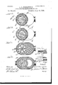
- Figure l represents a vertical section of the superheater connected with a generator, shown in dotted lines; Fig. 2, a section on line 2 2, Fig. l; Fig. 3, asection on line 3 3, Fig. l; 3o Fig. 4, a section on line 4 4, Fig. l; Fig. 5, a
- FIG. 3 5 A represents the generator, and A the superheater, the heating chamber A2 of which is provided with brick arranged in the usual way knownas checker work or brick.
- the checker brick may fill the chamber if desired, but I prefer to leave a space or sub-chamber ci for the purpose of mingling the hydrocarbon or other oils with the Water gas sent from the generator.
- the oils have heretofore been injected into the superheater on a line at an angle to the direction in which the water gas is moving.
- the object of such arrangement is to spray the oil toward the center of the current of water gas for the purpose of carbureting the same.
- Such an arrangement does not fully accomplish the object as the oil cannot be evenly distributed to the water gas; but on the contrary, that portion of the gas current that is nearest the nozzle receives too much oil and the part farthest away receives little or no oil.
- the result of this arrangement is the cooling of that part of the superheater nearest the spray because of the amount of oil received causing the formation of coal tar and. the overheating of the other 6o parts causing the formation of lamp black.
- the object of my construction is to deliver at the center of the uprising current of water gas, a spray of oil in such manner that the Acurrent of water gas will be thoroughly carbureted without wasting the oil as is the case when lamp'black and tar areformed in the carburetor.
- the spraying end a of the oil injector a2 is introduced into the 7o upper part of said chamber or space a with its center in the vertical center of said chamber so that the water gas will pass around and above it in its passage to the outlet A3.
- the oil under pressure will be introduced into the central partvof the current of ascending gas and which, owing to its velocity will distribute the vapor made from the oil more evenly than wouldl be t-he caseif the spray were projected into it at an angle. 8o
- the preferred means for carrying out this object is shown in the drawings.
- It consists of an injector a2, having a Iiattened end a with oblique openings a3 converging at a point outside the end in which they are placed so that 8 5 the oil jets which are forced into the injector are ejected into the superheating chamber at converging angles meeting ata common point, preferably the vertical center of the chamber and causing the meeting jets to form al spray 9o that is taken up by the Water gas.
- the injector is preferably protected from the heated currents passing through the superheater.
- the injector is shown in a lateral channel 0.4 leading throughV the wall of the superheater and top of the chamber a, which is in the form 0f an arch a5 to the center of the latter Where the flattened end of the inj ector is exposed through an opening c6 in the arch, so that the jets of oil 10o sprayed through the openings a3 will be sent downward to meet the upcoming currents of water gas.
- the injector can be secured in the passage in any desired way, preferably, by means that will permit of its removal when desired.
- the air can be forced into the checker work by means of a pipe B, vwhich terminates at the .inner side of the wall through which itis inserted, or as far into the checker vwork as maybefdesired, as ⁇ shownin Fig.v 6;. or it can be forced into-au annular recessb in the wall of the superheater and having openings b opposite the openings between the checker brick which are arranged at this point substantially as arrangedfthroughout the. su-perheater, Fig. 5, showing the arrangementy in the lower part of t-her superheater.
- the air soadmitted is distributed more evenly than would be the case. with the ⁇ device shown .in Fig. 6.
- Y Air may beadmittedat as many points as desired in the superheater.
- a second annular recess b2. having ⁇ openings b3 is shown above recess b andis connected therewith by avertical passage b4,-having-a.valve b5 for controlling theflow of air thereto.
- the airsu pplied in this second recess aids in heating the upper laye-rs of checker work, an .im-
- a superheater In a gas making machine, the combination of a superheater, checker work in said superheater, a chamber or space intermediate theupper and lower portions of said checker work, an-oil injector having its spraying nozzle providedwith oblique openings that project the oil downward toward a common point at-or near thevertical center of the chamber, and v an airop'ening in the superheater communileating with the-checker work above said chamber and oil injector to admit air to the upper portion of said superheater.
- a chamber intermedia-tethe upan oil injector having its body protectedby the brick forming the top of the chamber and its nozzle opening into the upper part of said chamber, and an opening in the superheater communicating with the checker brick immediately above the top of said chamber for admitting air to said checker work and cooling the top wall of said chamber.
- a superheater in said snperheater, a chamber intermediate the npper and lower portions of said checker brick, an oil injector connected with said chamber, an opening in the superheater immediately above the top of said chamber for admittingr air to said checker work above the chamber and cooling the top Wall of said chamber, and a second opening in said superheater for admitting air to the upper part of said checker brick above the chamber.
- a gas making apparatus the combination of a superheater, checker brick in said superheater, a chamber intermediate the upper and lower portions of said checker brick, an oil injector connected with said chamber, an opening in the snperheater immediately above the top of said chamber for admitting air to said checker brick above the chamber and cooling the top wall of said chamber, and a second opening in said superheater for ad mitting air to the upper partof said 1checker brick above the chamber, and connected with the lower opening by a passage provided with a valve.
Landscapes
- Chemical & Material Sciences (AREA)
- Chemical Kinetics & Catalysis (AREA)
- Organic Chemistry (AREA)
- Oil, Petroleum & Natural Gas (AREA)
- Engineering & Computer Science (AREA)
- Inorganic Chemistry (AREA)
- Combustion & Propulsion (AREA)
- General Health & Medical Sciences (AREA)
- Physics & Mathematics (AREA)
- Thermal Sciences (AREA)
- General Chemical & Material Sciences (AREA)
- Health & Medical Sciences (AREA)
- Production Of Liquid Hydrocarbon Mixture For Refining Petroleum (AREA)
Description
(NO Model.) 2 Sheets-Sheet 1.
L. L. MERRIFIELD. APPARATUS FOR MANUPAGT'URE OP GAS.
Patented June 18, 1895.
2 Sheets-Sheet 2.
(No Model.)
L. L. MERRIFIBLD. APPARATUS PoR MANUPAGTURE 0F GAS.
Patented June 18, 1.895.
Ill/ll UNITED. STATES PATENT OFFICE.
LEONARD LANCASTER MERRIFIELD, OF FRANKLIN, MASSACHUSETTS, AS- SIGNOR TO THE ECONOMICAL GAS APPARATUS CONSTRUCTION COM- PANY, LIMITED, OF TORONTO, CANADA.
APPARATUS FOR" MANUFACTURE OF GAS.
SPECIFICATION forming part of Letters Patent No. 541,107, dated J une 18, 1895.
Application tiled April 14,1894. Serial No. 507,551 (No model.)
To @ZZ whom it may concern:
Be it known that I, LEONARD LANCASTER MERRIFIELD, a citizen of the United States, residing at Franklin, in the county of Norfolk and State of Massachusetts, have invented certain newand useful Improvemen ts in Apparatus for Manufacturing Gas; and I do hereby declare the following to be a full, clear, and exact description of the invention, such as 1o will enable others skilled in the art to which it appertains to make and use the same.
My invention relates to that class of gas making apparatus shown and described in Patent No. 505,714, granted to Merrifield,
lVestcott and Pearson, September 26, 1893.
The object of my invention is to improve upon the general construction ot' the appara-' tus shown therein, particularly as to the admission of the air and the oil to the superzo heater.
To that end the invention consists of constructions and combinations, all as will hereinafter be described in the specification and pointed out in the claims, reference being had to the accompanying drawings, in which-j Figure l represents a vertical section of the superheater connected with a generator, shown in dotted lines; Fig. 2, a section on line 2 2, Fig. l; Fig. 3, asection on line 3 3, Fig. l; 3o Fig. 4, a section on line 4 4, Fig. l; Fig. 5, a
section on line 5 5, Fig. l; Fig. 6, a modification of the means for supplying the air; Fig. 7, a section of the injector, and Fig. S a bottom view of the same. 3 5 A, represents the generator, and A the superheater, the heating chamber A2 of which is provided with brick arranged in the usual way knownas checker work or brick. The checker brick may fill the chamber if desired, but I prefer to leave a space or sub-chamber ci for the purpose of mingling the hydrocarbon or other oils with the Water gas sent from the generator.
The oils have heretofore been injected into the superheater on a line at an angle to the direction in which the water gas is moving. The object of such arrangement is to spray the oil toward the center of the current of water gas for the purpose of carbureting the same. Such an arrangement, however, does not fully accomplish the object as the oil cannot be evenly distributed to the water gas; but on the contrary, that portion of the gas current that is nearest the nozzle receives too much oil and the part farthest away receives little or no oil. The result of this arrangement is the cooling of that part of the superheater nearest the spray because of the amount of oil received causing the formation of coal tar and. the overheating of the other 6o parts causing the formation of lamp black.
The object of my construction is to deliver at the center of the uprising current of water gas, a spray of oil in such manner that the Acurrent of water gas will be thoroughly carbureted without wasting the oil as is the case when lamp'black and tar areformed in the carburetor.
To carry out my invention the spraying end a of the oil injector a2 is introduced into the 7o upper part of said chamber or space a with its center in the vertical center of said chamber so that the water gas will pass around and above it in its passage to the outlet A3. In other words, the oil under pressure will be introduced into the central partvof the current of ascending gas and which, owing to its velocity will distribute the vapor made from the oil more evenly than wouldl be t-he caseif the spray were projected into it at an angle. 8o The preferred means for carrying out this object is shown in the drawings. It consists of an injector a2, having a Iiattened end a with oblique openings a3 converging at a point outside the end in which they are placed so that 8 5 the oil jets which are forced into the injector are ejected into the superheating chamber at converging angles meeting ata common point, preferably the vertical center of the chamber and causing the meeting jets to form al spray 9o that is taken up by the Water gas. The injector is preferably protected from the heated currents passing through the superheater. In the present Linstance the injector is shown in a lateral channel 0.4 leading throughV the wall of the superheater and top of the chamber a, which is in the form 0f an arch a5 to the center of the latter Where the flattened end of the inj ector is exposed through an opening c6 in the arch, so that the jets of oil 10o sprayed through the openings a3 will be sent downward to meet the upcoming currents of water gas. The injector can be secured in the passage in any desired way, preferably, by means that will permit of its removal when desired.
Heretotore it has been the practice .in heating up the superheater to introduce air into the chamber a to promote combustion. This arrangement, in fact makes the chamber a a secondary combustion chamber. In practice it has been found that the intense heat in this chamberheats the top chamber a, or the arch a5 to such a degree that it ultimately destroys it, causing great expense of renewal and break downs when least expected. It also heats the top courses of the checker brick below the arch to a very high temperature and` makes the temperature too high for the proper gasifying ofk the oil injected into said chamber. This intense heating of the chamber results in the deposition of the oil upon the ,archand some of the upper layers of the checker work in the form of globules of carbon. By avoiding the usel of airinthis intermediate chamber andprojecting the oil into thecenter of the upcoming currents of water gas these: objections are avoided to a'certain extent, and are completely overcome Vby the meansnow to be described. Air instead of being introduced into this chamber is introduced immediately above the arch directly into the checker work. The eiect ot the introduction of the air: at this point is to keep the arch cool thereby preventing the burning out of the injector, and also preventing the arch from becoming intensely heated and thereby carbonizing the oil thereon in the formvof globules of' carbon. The air can be forced into the checker work by means of a pipe B, vwhich terminates at the .inner side of the wall through which itis inserted, or as far into the checker vwork as maybefdesired, as `shownin Fig.v 6;. or it can be forced into-au annular recessb in the wall of the superheater and having openings b opposite the openings between the checker brick which are arranged at this point substantially as arrangedfthroughout the. su-perheater, Fig. 5, showing the arrangementy in the lower part of t-her superheater. The air soadmitted is distributed more evenly than would be the case. with the `device shown .in Fig. 6.
Y Air may beadmittedat as many points as desired in the superheater. In Fig.v l, a second annular recess b2. having `openings b3 is shown above recess b andis connected therewith by avertical passage b4,-having-a.valve b5 for controlling theflow of air thereto. The airsu pplied in this second recess aids in heating the upper laye-rs of checker work, an .im-
portant feature as the oil has become thoroughly vaporized bythe time it reaches the upper layers and becomes. Iixedasagas in combination with the water gas. It also makes the heat more uniform throughout the heater instead of having spots or places of the checker work above said chamber and` oil injector to admit air to the upper portion of said superheater.
' 2. In a gas making machine, the combination of a superheater, checker work in said superheater, a chamber or space intermediate theupper and lower portions of said checker work, an-oil injector having its spraying nozzle providedwith oblique openings that project the oil downward toward a common point at-or near thevertical center of the chamber, and v an airop'ening in the superheater communileating with the-checker work above said chamber and oil injector to admit air to the upper portion of said superheater.
3. Ina gas making apparatus, the combination of a superheater, checker work in said pervand lower portions of said checker work', an oil injectorl having its body protected by the brick work and its spraying nozzle opening downward into Athe upperpartof said chamber at a point substantially near the vertical center, andan air opening in the superheater communicating with the checker work above said chamber and oil injector to admit air to the upperportion of said-superheater.
4. Ina gask making apparatus, the combination of asuperheater, checker work in said superheater, a chamber intermediate the upperand .lower portions of said checker work,
an oil in j ectorhavin g a spraying nozzleformed.
with converging oblique open-ings in its under face and hav-ing its body protected by the brick work forming the upper part of said chamber; said oblique openings projecting the oil downward toward a common point at orvnear the vertical center ofthe chamber,
and au air opening in the superheater com-` mun'icatin g with the checker workabove said chamber and oil injector to admit air tothe upper portion ofsaid superheater.
5. In afgas making apparatus, the combination of asuperheater, checker brick in said superheater, acbamber formed intermediate the upperand .lower portions of the checker work, an oil injector having its nozzle in said chamber, and an opening in the-superheater communicating with the checker brick immediately above the top of said chamber for loo 1053` :zek
admitting air to said checker work and cool l ing the top wall of said chamber.
6. Inra gasl making apparatus, the combination-of a superheater, checker brick in said ysuperheater, achamber. intermediate the upper and lower portions of said checker brick,
superheater, a chamber intermedia-tethe upan oil injector having its body protectedby the brick forming the top of the chamber and its nozzle opening into the upper part of said chamber, and an opening in the superheater communicating with the checker brick immediately above the top of said chamber for admitting air to said checker work and cooling the top wall of said chamber.
7. In a gas making apparatus, the combination of a superheater, checker brick in said snperheater, a chamber intermediate the npper and lower portions of said checker brick, an oil injector connected with said chamber, an opening in the superheater immediately above the top of said chamber for admittingr air to said checker work above the chamber and cooling the top Wall of said chamber, and a second opening in said superheater for admitting air to the upper part of said checker brick above the chamber.
S. In a gas making apparatus, the combination of a superheater, checker brick in said superheater, a chamber intermediate the upper and lower portions of said checker brick, an oil injector connected with said chamber, an opening in the snperheater immediately above the top of said chamber for admitting air to said checker brick above the chamber and cooling the top wall of said chamber, and a second opening in said superheater for ad mitting air to the upper partof said 1checker brick above the chamber, and connected with the lower opening by a passage provided with a valve.
In testimony whereof I aftix my signature in presence of two witnesses.
LEONARD LANCASTER MERRIFIELD.
Titnesses:
H. G. RoAT, C. E. RoAT.
Publications (1)
| Publication Number | Publication Date |
|---|---|
| US541107A true US541107A (en) | 1895-06-18 |
Family
ID=2609863
Family Applications (1)
| Application Number | Title | Priority Date | Filing Date |
|---|---|---|---|
| US541107D Expired - Lifetime US541107A (en) | Signor to the economical gas apparatus construction com |
Country Status (1)
| Country | Link |
|---|---|
| US (1) | US541107A (en) |
-
0
- US US541107D patent/US541107A/en not_active Expired - Lifetime
Similar Documents
| Publication | Publication Date | Title |
|---|---|---|
| US541107A (en) | Signor to the economical gas apparatus construction com | |
| US370251A (en) | Half to edward b | |
| US322791A (en) | Heating-burner for gas and other hydrocarbons | |
| US372687A (en) | Method of and apparatus for mingling gases | |
| US460189A (en) | Smoke-consuming furnace | |
| US556104A (en) | Gas or oil burner | |
| US504129A (en) | Vapor-burner | |
| US459789A (en) | Domestic vapor-burner | |
| US245062A (en) | Apparatus for burning oil | |
| US669757A (en) | Vaporizer. | |
| US861444A (en) | Hydrocarbon-burner. | |
| US231232A (en) | Island | |
| US495917A (en) | Gas apparatus | |
| US100572A (en) | Improvement in vapor-burners | |
| US741820A (en) | Oil-burner. | |
| US1086519A (en) | Liquid-fuel burner. | |
| US534040A (en) | Vapor-burner | |
| US623559A (en) | Francis jarvis patten | |
| US1025054A (en) | Hydrocarbon-furnace. | |
| US329481A (en) | Vapor-burner | |
| US888707A (en) | Incandescent vapor-burner. | |
| US371784A (en) | Hydrocarbon-furnace | |
| US238852A (en) | Burning hydrocarbon | |
| US684836A (en) | Carbureter. | |
| US890940A (en) | Gas apparatus. |