US5405190A - Cover for vehicle head restraint - Google Patents
Cover for vehicle head restraint Download PDFInfo
- Publication number
- US5405190A US5405190A US08/005,892 US589293A US5405190A US 5405190 A US5405190 A US 5405190A US 589293 A US589293 A US 589293A US 5405190 A US5405190 A US 5405190A
- Authority
- US
- United States
- Prior art keywords
- cover
- framework
- head restraint
- fabric
- free edges
- Prior art date
- Legal status (The legal status is an assumption and is not a legal conclusion. Google has not performed a legal analysis and makes no representation as to the accuracy of the status listed.)
- Expired - Lifetime
Links
Images


Classifications
-
- B—PERFORMING OPERATIONS; TRANSPORTING
- B60—VEHICLES IN GENERAL
- B60N—SEATS SPECIALLY ADAPTED FOR VEHICLES; VEHICLE PASSENGER ACCOMMODATION NOT OTHERWISE PROVIDED FOR
- B60N2/00—Seats specially adapted for vehicles; Arrangement or mounting of seats in vehicles
- B60N2/80—Head-rests
-
- B—PERFORMING OPERATIONS; TRANSPORTING
- B29—WORKING OF PLASTICS; WORKING OF SUBSTANCES IN A PLASTIC STATE IN GENERAL
- B29L—INDEXING SCHEME ASSOCIATED WITH SUBCLASS B29C, RELATING TO PARTICULAR ARTICLES
- B29L2031/00—Other particular articles
- B29L2031/30—Vehicles, e.g. ships or aircraft, or body parts thereof
- B29L2031/3005—Body finishings
- B29L2031/3023—Head-rests
-
- Y—GENERAL TAGGING OF NEW TECHNOLOGICAL DEVELOPMENTS; GENERAL TAGGING OF CROSS-SECTIONAL TECHNOLOGIES SPANNING OVER SEVERAL SECTIONS OF THE IPC; TECHNICAL SUBJECTS COVERED BY FORMER USPC CROSS-REFERENCE ART COLLECTIONS [XRACs] AND DIGESTS
- Y10—TECHNICAL SUBJECTS COVERED BY FORMER USPC
- Y10S—TECHNICAL SUBJECTS COVERED BY FORMER USPC CROSS-REFERENCE ART COLLECTIONS [XRACs] AND DIGESTS
- Y10S297/00—Chairs and seats
- Y10S297/01—Foam
Definitions
- This invention relates to head restraints and has particular, but not necessarily exclusive, reference to head restraints for use on vehicles seats.
- Head restraints are increasingly becoming a standard fitment to vehicles to reduce the dangers to an occupant of so-called whiplash injuries. Head restraints may be formed integrally with the seat or may be formed as a separate component mounted in such a way as to be adjustable on the seat.
- the present invention is concerned with a head restraint particularly suitable for mounting on a pillar or pair of pillars for vertical adjustment on a seat.
- a head restraint for a vehicle seat the head restraint being of generally annular shape and including an annular framework, there being resilient foam covering over part at least of the framework, and a fabric cover covering over the resilient foam, wherein the cover is of three dimensional knitted construction, the cover being tautly wrapped around the framework and foam covering, and the free edges of the cover being secured in close relationship to leave the cover encompassing the framework and foam covering.
- the fabric cover may be in the form of a waisted tube in the unassembled condition of the head restraint.
- the waisted tube may be integrally knitted in a single jersey construction on a knitting machine having two opposed needle beds.
- the cover may alternatively be of a double jersey construction and may be knitted as a double jersey seamless tube on a four bed knitting machine, or may be formed on a two bed knitting machine and be provided with a seam. The seam may be sewn together.
- the free edges of the fabric cover may be secured in abutting face-to-face relationship. They may be secured in an outwardly directed groove.
- the edges may be tubular and may contain a cord.
- the cord may be elasticated.
- the edges may have an integrally knitted elasticated portion.
- the free edges of the fabric cover may be clamped between two halves of the framework.
- the fabric cover may be in the form of a pair of double jersey three dimensionally knitted open rectangles of generally gutter shape in cross-section.
- the open rectangles may be seamed together around the inside or the outside. Alternatively the knitted rectangles may be clamped together between two parts of the framework.
- the foam covering may be preformed and the cover may be wrapped around the foam.
- the cover may be located over the framework and the foam may be formed in situ between the cover and the framework.
- the cover is preferably a weft knitted double jersey fabric knitted with an air-textured continuous filament synthetic yarn on a knitting machine having a gauge of 10 to 14.
- a gauge of 10 to 14 means that there are 10 to 14 needles per inch (2.54 cms)).
- the fabric preferably has, in the relaxed state, from 4 to 6 wales per cm and from 10.5 to 22 courses per cm.
- the yarn used preferably has a count of 550 to 850 decitex, particularly 650 to 800 decitex and is preferably an air textured polyester yarn.
- the fabric may be knitted in accordance with the method described in GB-A-2,223,035, the contents of which are incorporated herein by way of reference.
- FIG. 1 is a perspective view of a head restraint located on a seat
- FIG. 2 is a schematic face view of the head restraint of FIG. 1,
- FIG. 3 is a partial section of FIG. 1 along the line III--III,
- FIG. 4 is a plan view of a knitted cover prior to seaming
- FIG. 5 is a perspective view of the cover of FIG. 4 seamed
- FIG. 6 is an enlarged view of the part of FIG. 5 within the circle VI,
- FIG. 7 is an enlarged view of the part of FIG. 3 within the circle VII,
- FIG. 8 is an enlarged view of the part of FIG. 1 within the circle VIII,
- FIG. 9 illustrates a schematic perspective view of a second embodiment of head restraint
- FIG. 10 illustrates a fabric cover half for the head restraint of FIG. 9,
- FIG. 11 is a sectional view of FIG. 10 along the line XI--XI,
- FIG. 12 is a cross sectional view of FIG. 9 along the line of XII--XII, and
- FIG. 13 is an enlarged view of a connection between two half annuli similar to that incorporated within the circle XIII of FIG. 12.
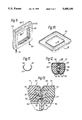
- a seat 1 is provided with a head restraint generally indicated by 2.
- the head restraint is mounted on a pair of rods or pillars 3,4.
- the head restraint 2 is of generally annular shape. Such a shape is sometimes referred to as a doughnut shape.
- the pillars 3,4 are aligned with upright portions of the head restraint as may be seen more easily in FIG. 2.
- the important components of the head restraint 2 effectively comprise a framework 5 of generally annular shape having a pair of recesses 6,7 to receive the rods or pillars 3,4 (e.g. of metal) which support the head restraint.
- a framework 5 Surrounding the framework 5--which is typically of rigid plastics material such as polypropylene--is a foam covering 10 which provides resilience to the head restraint.
- a fabric cover 11 Surrounding the framework 5--which is typically of rigid plastics material such as polypropylene--is a foam covering 10 which provides resilience to the head restraint.
- a fabric cover 11 Surrounding the framework 5--which is typically of rigid plastics material such as polypropylene--is a foam covering 10 which provides resilience to the head restraint.
- a fabric cover 11 Surrounding the framework 5--which is typically of rigid plastics material such as polypropylene--is a foam covering 10 which provides resilience to the head restraint.
- a fabric cover 11 Surrounding the framework 5-
- the fabric cover of one embodiment of the invention is shown in more detail in FIGS. 4 to 6.
- the fabric cover of this embodiment is a three dimensionally knitted structure 12 having a generally waisted rectangular shape as shown in FIG. 4.
- the structure 12 is provided at each of its ends 13,14 with an integral tubular portion.
- the cover 11 is knitted on a flat V-bed knitting machine in a double jersey structure using an air textured polyester continuous filament yarn of 750 decitex.
- the double jersey construction of the main portion of the cover is formed by interlinking the jersey structures of the two faces.
- the tubular portions 13 and 14 are produced by separating the two faces to produce a double layer single jersey structure. By rejoining the faces on the knitting machine a tubular portion can be produced.
- the method of manufacturing such tubular hems is described in the specification of GB-A-2,223,034, the contents of which are incorporated herein by way of reference.
- the cover 11 shown in FIG. 4 is not produced in a completely flat manner. It is so produced that on folding to the structure shown in FIG. 5 a waisted tubular structure is produced.
- the edges 15,16 of the cover 11 are joined together by a seam, as at 17, so as to produce the generally waisted tubular member shown.
- the outside of the tube, as shown in FIG. 5, is the reverse of the fabric and the inside of the tube exhibits the face of the fabric which is exposed and thus on view in the assembled head restraint 2.
- the seam 17 terminates close to the end of the tubular member showing the tubular hem 13. It will be appreciated that in FIG. 6 both ends of the tubular hem 13 can be seen. An elastic cord is then inserted into the tubular hem 13. If required the cord can be inserted before the seam 17 is formed.
- One tubular end is then pushed through the central aperture in a preprepared annular foam covered framework and the tubular cover is folded outwardly so that the hems 13 and 14 lie around the outer periphery of the foam covered framework.
- the framework 18 has a recess 19 for accommodating the support rod 4.
- the framework also incorporates a U-shaped channel member 20 extending around substantially the whole of the periphery of the framework held by legs 21, 22 on the body of the framework.
- a foam covering 23 Surrounding the framework 18 is a foam covering 23.
- the edges of the cover are pushed into the groove in the U-shaped member 20. This is shown in more detail in FIG. 7.
- the U-shaped member 20 receives the two tubular hems 13, 14 in which there are located elastic cords 27,28.
- the edges of the tubular hems 13, 14 are pulled tight in the U-shaped member 20 pulling edge regions 29,30 of the cover into the groove.
- the seam 17 is so arranged as to lie at the lowermost point 31 of the head restraint. As can be seen in FIG. 8 the seam 17 cuts into the foam covering 23.
- the seam may be double locked as shown at 25 in FIG. 8.
- one or both edges of the cover 11 can be formed with recesses to accomodate the support pillars for the head restraint.
- the cover may be formed with integral apertures to permit the head restraint support pillars to pass through the cover prior to assembly of the cover.
- FIGS. 9 to 13 illustrate a second, alternative, embodiment of the invention.
- FIG. 9 shows a head restraint 50 of generally annular shape again located on support rods or pillars 51,52.
- the head restraint 50 again comprises an annular framework encompassed by a foam covering and having an outer fabric cover.
- the three dimensional knitted double jersey fabric cover is formed in two halves 53 and 54.
- Each half is of a generally open rectangular shape and in cross section is of generally gutter shape.
- One half 53 is shown in more detail in FIGS. 10 and 11. As can be seen from FIG. 10, the half 53 has a curved rectangular shape in plan and, as may clearly be seen in FIG. 11 (which is a section of FIG.
- FIG. 10 along the line XI--XI), is of generally U-shape in cross-section.
- the structure of FIG. 10 may be knitted in a double jersey construction on a flat V-bed knitting machine.
- Preferably the upper edges 55,56 of the gutter shape 57 are inwardly directed.
- FIG. 12 the two open rectangular covers 53, 54 encompass two foam cores 58,59.
- FIG. 12 which is a section of FIG. 9 through the line XII--XII shows the peripheral edges of the two half fabric covers trapped between extensions 60,61,62,63 of framework members 64 and 65.
- the two framework members 64 and 65 each constitute roughly half of the framework and may be snap-locked together as at 66.
- FIG. 13 shows in more detail how a head restraint can be produced by the snapping together of two half doughnuts so that the action of snapping together the two halves forms the complete doughnut and also retains the fabric cover in position. It will be appreciated that FIG. 13 illustrates in detail the connection between the two portions of the half head restraints illustrated generally within the circle XIII of FIG. 12.
- each half doughnut can be prepared with a framework member 69,70 and a fabric cover 71,72 stretched over an internal foam covering 73, 74 for the framework.
- the framework 69 has an aperture 75 which coincides with an aperture 76 in the fabric cover 67.
- the framework 70 is provided with a spigot 77 which extends through an aperture 78 in the fabric cover 72, through the aperture 76 and through the aperture 75.
- An enlarged head 79 on the spigot 77 locks into the framework 69 to retain the two halves together. It will be appreciated that a number of spigots and holes would be provided around the periphery of the framework to hold the two half sections together. It will also be appreciated that further smaller spigots may be produced on each of the framework halves to retain the fabric cover in position prior to assembly of the whole head restraint 50.
- the fabric cover can be loosely located on the framework and the foam coverings 73,74 may be produced inside this by foaming in situ.
- double jersey upholstered structures in which the fabric is produced either as a two-part construction, as illustrated in FIGS. 9 to 13, or as a single, seamed construction as is illustrated in FIGS. 1 to 8.
- a double jersey fabric on a knitting machine having two opposed needle beds it is either possible to knit a tubular single jersey structure including a waisted single jersey tube or a double jersey structure can be produced which requires either seaming or assembly in two parts.
- double jersey material is required for reasons of resistance to abrasion and strength. Head restraints, however, have much less abrasive conditions to encounter and it is feasible that single jersey structures could be used for such seat components.
- the present invention provides a head restraint having on its exterior face far fewer seams than prior art head restraints and the head restraint can therefore have a close fitting smooth cover.
- the head restraint with the three dimensionally knitted upholstery cover is much smoother, closer fitting, and is easier to assemble.
Landscapes
- Engineering & Computer Science (AREA)
- Aviation & Aerospace Engineering (AREA)
- Transportation (AREA)
- Mechanical Engineering (AREA)
- Knitting Of Fabric (AREA)
- Chair Legs, Seat Parts, And Backrests (AREA)
- Seats For Vehicles (AREA)
- Mattresses And Other Support Structures For Chairs And Beds (AREA)
- Woven Fabrics (AREA)
- Air Bags (AREA)
Abstract
Description
Claims (4)
Applications Claiming Priority (2)
| Application Number | Priority Date | Filing Date | Title |
|---|---|---|---|
| GB9200938 | 1992-01-16 | ||
| GB9200938A GB2263632B (en) | 1992-01-16 | 1992-01-16 | Head restraint |
Publications (1)
| Publication Number | Publication Date |
|---|---|
| US5405190A true US5405190A (en) | 1995-04-11 |
Family
ID=10708725
Family Applications (1)
| Application Number | Title | Priority Date | Filing Date |
|---|---|---|---|
| US08/005,892 Expired - Lifetime US5405190A (en) | 1992-01-16 | 1993-01-15 | Cover for vehicle head restraint |
Country Status (10)
| Country | Link |
|---|---|
| US (1) | US5405190A (en) |
| EP (1) | EP0552038B1 (en) |
| JP (1) | JPH05253035A (en) |
| AU (1) | AU661530B2 (en) |
| BR (1) | BR9300130A (en) |
| CA (1) | CA2087141A1 (en) |
| DE (1) | DE69305539T2 (en) |
| ES (1) | ES2093358T3 (en) |
| GB (1) | GB2263632B (en) |
| MX (1) | MX9300145A (en) |
Cited By (28)
| Publication number | Priority date | Publication date | Assignee | Title |
|---|---|---|---|---|
| US5664840A (en) * | 1995-12-23 | 1997-09-09 | R. Schmidt Gmbh | Headrest for motor-vehicle seat |
| US5700057A (en) * | 1996-07-16 | 1997-12-23 | Gestind-M.B. "Manifattura Di Brusolo" S.P.A. | Headrest for motor vehicle seats and a method for its manufacturing |
| US5882073A (en) * | 1996-08-30 | 1999-03-16 | Woodbridge Foam Corporation | Foam passenger seat having trim cover attachment means |
| US5896823A (en) * | 1996-05-14 | 1999-04-27 | Inoac Corporation | Method of manufacturing head rest skin |
| US5927814A (en) * | 1998-06-18 | 1999-07-27 | Tachi-S Co., Ltd. | Headrest |
| US5984414A (en) * | 1997-12-31 | 1999-11-16 | Tachi-S Co., Ltd. | Headrest |
| US6056358A (en) * | 1997-11-28 | 2000-05-02 | Gestind M.B. Manifattura Di Bruzolo S.P.A. | Head-rest for a car seat |
| US6164226A (en) * | 1999-02-12 | 2000-12-26 | Tachi-S Co., Ltd. | Method for forming a trim cover assembly of a donut-like or annular headrest for a vehicle seat |
| USD436260S1 (en) | 1999-11-08 | 2001-01-16 | Okamura Corporation | Chair |
| US6183045B1 (en) * | 1998-06-03 | 2001-02-06 | Magna Interior Systems Inc. | Method of manufacturing an interior automotive component and components made therefrom |
| USD437132S1 (en) | 1999-11-08 | 2001-02-06 | Okamura Corporation | Chair |
| US6224158B1 (en) * | 1999-11-08 | 2001-05-01 | Illinois Tool Works Inc. | Headrest assembly |
| USD469618S1 (en) | 2000-11-01 | 2003-02-04 | Okamura Corporation | Chair |
| USD476493S1 (en) | 2000-11-01 | 2003-07-01 | Okamura Corporation | Chair |
| USD476820S1 (en) | 2000-11-01 | 2003-07-08 | Okamura Corporation | Chair |
| USD492154S1 (en) | 2001-04-12 | 2004-06-29 | Jimmy E Martial | Vehicle head rest cover |
| US6857699B2 (en) | 2002-08-22 | 2005-02-22 | Eagle Ottawa, Llc | Head restraint assembly and method for its manufacturing |
| US20070108804A1 (en) * | 2005-11-16 | 2007-05-17 | Shigeru Adachi | Headrest, seat for vehicle, and method for manufacturing headrest |
| US20070257537A1 (en) * | 2004-05-28 | 2007-11-08 | Asbury James D | Two-peice head restraint and method for making same |
| US20080164730A1 (en) * | 2007-01-05 | 2008-07-10 | Ford Global Technologies, Llc | Insert for vehicle seat head restraint |
| US20080185900A1 (en) * | 2006-09-28 | 2008-08-07 | Lee Ellen Cheng-Ch | Use of renewable and biodegradable materials for automotive interiors |
| US20080203781A1 (en) * | 2004-12-24 | 2008-08-28 | Daimlerchrylser Ag | Air Nozzle Arranged In The Head Rest Of A Vehicle Seat |
| FR2948077A1 (en) * | 2009-07-17 | 2011-01-21 | Cera | Headrest for seat of motor vehicle, has formats with cord slidably assembled in peripheral housing unit, where cord is closed in tight loop so as to assure fixation of corresponding formats in tightness |
| US20130134760A1 (en) * | 2011-11-28 | 2013-05-30 | Ford Global Technologies, Llc | Dual firmness head restraint |
| US20130200679A1 (en) * | 2010-08-13 | 2013-08-08 | Johnson Controls Gmbh | Method for producing head restraints for vehicle seats and one such head restraint |
| US10149546B2 (en) * | 2016-07-13 | 2018-12-11 | Toyota Boshoku Kabushiki Kaisha | Cushion pad of vehicle seat and manufacturing method thereof |
| US10179433B2 (en) * | 2017-03-02 | 2019-01-15 | Ford Global Technologies, Llc | Method of forming a headrest assembly |
| US20210213859A1 (en) * | 2020-01-14 | 2021-07-15 | Honda Motor Co., Ltd. | Headrest, vehicle seat and vehicle |
Families Citing this family (2)
| Publication number | Priority date | Publication date | Assignee | Title |
|---|---|---|---|---|
| FR2715040B1 (en) * | 1994-01-14 | 1996-04-05 | Cesa | Seat cover and its application in particular to a seat with headrest. |
| DE19633749B4 (en) * | 1996-08-22 | 2005-03-03 | Tachi-S Co., Ltd., Akishima | headrest |
Citations (10)
| Publication number | Priority date | Publication date | Assignee | Title |
|---|---|---|---|---|
| JPS5254761A (en) * | 1975-10-31 | 1977-05-04 | Toyota Motor Co Ltd | Process for manufacturing foamed cushion having skin |
| DE2715027A1 (en) * | 1976-04-05 | 1977-10-13 | Tachikawa Spring Co | SEAT PAD |
| JPS5442297A (en) * | 1977-09-10 | 1979-04-04 | Ube Nitto Kasei Co | Bundling band of compressive elasticity and method of making said band |
| GB2164248A (en) * | 1984-09-10 | 1986-03-19 | Nissan Motor | Headrest and method of producing same |
| FR2577869A1 (en) * | 1985-02-26 | 1986-08-29 | Gestind Mb Manifattura Bruzolo | Headrest for vehicle seats |
| US4738809A (en) * | 1985-08-01 | 1988-04-19 | Grammer Sitzsysteme Gmbh | Process and apparatus for the production of a cushion element |
| DE3736828A1 (en) * | 1987-10-30 | 1989-05-18 | Audi Ag | HEADREST FOR A MOTOR VEHICLE |
| EP0341683A2 (en) * | 1988-05-11 | 1989-11-15 | PETER BUTZ GmbH & Co Verwaltungs-KG | Headrest for motor vehicle seats |
| DE4105439A1 (en) * | 1991-02-21 | 1992-08-27 | Schmidt Gmbh R | Head support for vehicle seat - has joined two U=shaped frame sections welded adjacent to frame shanks |
| US5165754A (en) * | 1990-09-19 | 1992-11-24 | Cesa-Compagnie Europeenne De Sieges Pour Automobiles | Headrest with closed cell cushion and a covering having an auto formed surface film and overmoulded underlayer |
Family Cites Families (3)
| Publication number | Priority date | Publication date | Assignee | Title |
|---|---|---|---|---|
| JPS5834653B2 (en) * | 1976-03-09 | 1983-07-28 | トヨタ自動車株式会社 | multi-cylinder internal combustion engine |
| JP2794450B2 (en) * | 1989-05-30 | 1998-09-03 | 株式会社ジェイエスピー | Conductive polyethylene foam particles |
| JP3101300B2 (en) * | 1990-07-13 | 2000-10-23 | 三洋電機株式会社 | Organic electroluminescent device |
-
1992
- 1992-01-16 GB GB9200938A patent/GB2263632B/en not_active Expired - Fee Related
- 1992-12-31 AU AU30486/92A patent/AU661530B2/en not_active Ceased
-
1993
- 1993-01-12 CA CA002087141A patent/CA2087141A1/en not_active Abandoned
- 1993-01-13 JP JP5004109A patent/JPH05253035A/en active Pending
- 1993-01-13 BR BR9300130A patent/BR9300130A/en not_active Application Discontinuation
- 1993-01-13 MX MX9300145A patent/MX9300145A/en not_active IP Right Cessation
- 1993-01-14 EP EP93300232A patent/EP0552038B1/en not_active Expired - Lifetime
- 1993-01-14 DE DE69305539T patent/DE69305539T2/en not_active Expired - Fee Related
- 1993-01-14 ES ES93300232T patent/ES2093358T3/en not_active Expired - Lifetime
- 1993-01-15 US US08/005,892 patent/US5405190A/en not_active Expired - Lifetime
Patent Citations (10)
| Publication number | Priority date | Publication date | Assignee | Title |
|---|---|---|---|---|
| JPS5254761A (en) * | 1975-10-31 | 1977-05-04 | Toyota Motor Co Ltd | Process for manufacturing foamed cushion having skin |
| DE2715027A1 (en) * | 1976-04-05 | 1977-10-13 | Tachikawa Spring Co | SEAT PAD |
| JPS5442297A (en) * | 1977-09-10 | 1979-04-04 | Ube Nitto Kasei Co | Bundling band of compressive elasticity and method of making said band |
| GB2164248A (en) * | 1984-09-10 | 1986-03-19 | Nissan Motor | Headrest and method of producing same |
| FR2577869A1 (en) * | 1985-02-26 | 1986-08-29 | Gestind Mb Manifattura Bruzolo | Headrest for vehicle seats |
| US4738809A (en) * | 1985-08-01 | 1988-04-19 | Grammer Sitzsysteme Gmbh | Process and apparatus for the production of a cushion element |
| DE3736828A1 (en) * | 1987-10-30 | 1989-05-18 | Audi Ag | HEADREST FOR A MOTOR VEHICLE |
| EP0341683A2 (en) * | 1988-05-11 | 1989-11-15 | PETER BUTZ GmbH & Co Verwaltungs-KG | Headrest for motor vehicle seats |
| US5165754A (en) * | 1990-09-19 | 1992-11-24 | Cesa-Compagnie Europeenne De Sieges Pour Automobiles | Headrest with closed cell cushion and a covering having an auto formed surface film and overmoulded underlayer |
| DE4105439A1 (en) * | 1991-02-21 | 1992-08-27 | Schmidt Gmbh R | Head support for vehicle seat - has joined two U=shaped frame sections welded adjacent to frame shanks |
Cited By (39)
| Publication number | Priority date | Publication date | Assignee | Title |
|---|---|---|---|---|
| US5664840A (en) * | 1995-12-23 | 1997-09-09 | R. Schmidt Gmbh | Headrest for motor-vehicle seat |
| US5896823A (en) * | 1996-05-14 | 1999-04-27 | Inoac Corporation | Method of manufacturing head rest skin |
| US5700057A (en) * | 1996-07-16 | 1997-12-23 | Gestind-M.B. "Manifattura Di Brusolo" S.P.A. | Headrest for motor vehicle seats and a method for its manufacturing |
| US5882073A (en) * | 1996-08-30 | 1999-03-16 | Woodbridge Foam Corporation | Foam passenger seat having trim cover attachment means |
| US6056358A (en) * | 1997-11-28 | 2000-05-02 | Gestind M.B. Manifattura Di Bruzolo S.P.A. | Head-rest for a car seat |
| US5984414A (en) * | 1997-12-31 | 1999-11-16 | Tachi-S Co., Ltd. | Headrest |
| US6183045B1 (en) * | 1998-06-03 | 2001-02-06 | Magna Interior Systems Inc. | Method of manufacturing an interior automotive component and components made therefrom |
| US5927814A (en) * | 1998-06-18 | 1999-07-27 | Tachi-S Co., Ltd. | Headrest |
| US6164226A (en) * | 1999-02-12 | 2000-12-26 | Tachi-S Co., Ltd. | Method for forming a trim cover assembly of a donut-like or annular headrest for a vehicle seat |
| USD436260S1 (en) | 1999-11-08 | 2001-01-16 | Okamura Corporation | Chair |
| USD437132S1 (en) | 1999-11-08 | 2001-02-06 | Okamura Corporation | Chair |
| US6224158B1 (en) * | 1999-11-08 | 2001-05-01 | Illinois Tool Works Inc. | Headrest assembly |
| US6789850B1 (en) * | 1999-11-08 | 2004-09-14 | Illinois Tool Works Inc. | Headrest assembly |
| USD469618S1 (en) | 2000-11-01 | 2003-02-04 | Okamura Corporation | Chair |
| USD476493S1 (en) | 2000-11-01 | 2003-07-01 | Okamura Corporation | Chair |
| USD476820S1 (en) | 2000-11-01 | 2003-07-08 | Okamura Corporation | Chair |
| USD492154S1 (en) | 2001-04-12 | 2004-06-29 | Jimmy E Martial | Vehicle head rest cover |
| US20050140198A1 (en) * | 2002-08-22 | 2005-06-30 | Eagle Ottawa, Llc | Head restraint assembly and method for its manufacturing |
| US7222401B2 (en) | 2002-08-22 | 2007-05-29 | Eagle Ottawa, Llc | Method for making a head restraint assembly |
| US6857699B2 (en) | 2002-08-22 | 2005-02-22 | Eagle Ottawa, Llc | Head restraint assembly and method for its manufacturing |
| US20070257537A1 (en) * | 2004-05-28 | 2007-11-08 | Asbury James D | Two-peice head restraint and method for making same |
| US7819480B2 (en) * | 2004-05-28 | 2010-10-26 | Magna International Inc. | Two-piece head restraint and method for making same |
| US20080203781A1 (en) * | 2004-12-24 | 2008-08-28 | Daimlerchrylser Ag | Air Nozzle Arranged In The Head Rest Of A Vehicle Seat |
| US20070108804A1 (en) * | 2005-11-16 | 2007-05-17 | Shigeru Adachi | Headrest, seat for vehicle, and method for manufacturing headrest |
| US7367603B2 (en) * | 2005-11-16 | 2008-05-06 | Ts Tech Co., Ltd. | Headrest, seat for vehicle, and method for manufacturing headrest |
| US20080185900A1 (en) * | 2006-09-28 | 2008-08-07 | Lee Ellen Cheng-Ch | Use of renewable and biodegradable materials for automotive interiors |
| US20080164730A1 (en) * | 2007-01-05 | 2008-07-10 | Ford Global Technologies, Llc | Insert for vehicle seat head restraint |
| FR2948077A1 (en) * | 2009-07-17 | 2011-01-21 | Cera | Headrest for seat of motor vehicle, has formats with cord slidably assembled in peripheral housing unit, where cord is closed in tight loop so as to assure fixation of corresponding formats in tightness |
| US9102254B2 (en) * | 2010-08-13 | 2015-08-11 | Johnson Controls Technology Company | Method for producing head restraints for vehicle seats and one such head restraint |
| US20130200679A1 (en) * | 2010-08-13 | 2013-08-08 | Johnson Controls Gmbh | Method for producing head restraints for vehicle seats and one such head restraint |
| US20130134760A1 (en) * | 2011-11-28 | 2013-05-30 | Ford Global Technologies, Llc | Dual firmness head restraint |
| US10011058B2 (en) * | 2011-11-28 | 2018-07-03 | Ford Global Technologies, Llc | Dual firmness head restraint |
| US10149546B2 (en) * | 2016-07-13 | 2018-12-11 | Toyota Boshoku Kabushiki Kaisha | Cushion pad of vehicle seat and manufacturing method thereof |
| US10179433B2 (en) * | 2017-03-02 | 2019-01-15 | Ford Global Technologies, Llc | Method of forming a headrest assembly |
| US10543631B2 (en) | 2017-03-02 | 2020-01-28 | Ford Global Technologies, Llc | Method of forming a headset assembly |
| US20200122368A1 (en) * | 2017-03-02 | 2020-04-23 | Ford Global Technologies, Llc | Method of forming a headrest assembly |
| US10933569B2 (en) * | 2017-03-02 | 2021-03-02 | Ford Global Technologies, Llc | Method of forming a headrest assembly |
| US20210213859A1 (en) * | 2020-01-14 | 2021-07-15 | Honda Motor Co., Ltd. | Headrest, vehicle seat and vehicle |
| US11173820B2 (en) * | 2020-01-14 | 2021-11-16 | Honda Motor Co., Ltd. | Headrest, vehicle seat and vehicle |
Also Published As
| Publication number | Publication date |
|---|---|
| DE69305539D1 (en) | 1996-11-28 |
| EP0552038B1 (en) | 1996-10-23 |
| CA2087141A1 (en) | 1993-07-17 |
| GB2263632B (en) | 1995-11-01 |
| AU3048692A (en) | 1993-07-22 |
| DE69305539T2 (en) | 1997-02-20 |
| ES2093358T3 (en) | 1996-12-16 |
| EP0552038A1 (en) | 1993-07-21 |
| BR9300130A (en) | 1993-07-20 |
| GB2263632A (en) | 1993-08-04 |
| JPH05253035A (en) | 1993-10-05 |
| AU661530B2 (en) | 1995-07-27 |
| MX9300145A (en) | 1993-11-01 |
| GB9200938D0 (en) | 1992-03-11 |
Similar Documents
| Publication | Publication Date | Title |
|---|---|---|
| US5405190A (en) | Cover for vehicle head restraint | |
| US5013089A (en) | Thin profile integrated suspension and seat trim cover | |
| US7025424B2 (en) | Chair back for a chair | |
| EP0361855B1 (en) | Upholstery fabric | |
| JP2790444B2 (en) | Structure covered with cloth cover and method of attaching cloth cover | |
| US5887452A (en) | Knitted cover | |
| US4798416A (en) | Seat, particularly a vehicle seat | |
| AU641848B2 (en) | Upholstery fabric | |
| US6401643B2 (en) | Sewn cover assembly and product foamed therewith | |
| CN114144095A (en) | Fabric for modular chair | |
| US6401496B1 (en) | Method for producing knitted fabrics with integrated fasteners | |
| JP2001340175A (en) | Independent cushion body | |
| CN110053531B (en) | Carrier seat | |
| GB2253219A (en) | Attachment wire and fabric structure for upholstery cover | |
| WO2003039298A1 (en) | Suspension fabric for seating | |
| US6430969B1 (en) | Device for securing a two-layered knitted fabric to a support | |
| US6663175B2 (en) | Vehicle seat cover, and a vehicle seat including such a cover | |
| JP4332868B2 (en) | Seat having a seat portion by a planar elastic body | |
| US10973341B2 (en) | Knitted-in laces for shaping and fitting textiles and fabrics | |
| JP2003328263A (en) | Processing method of molded article using cloth and molded article using cloth | |
| CN115107610B (en) | Head restraint assembly with pillow and method of manufacture | |
| CA2470488C (en) | Chair back for a chair | |
| JP2025097128A (en) | Seat cover hanging structure, vehicle seat, and method for manufacturing hanging structure | |
| JPH0421316Y2 (en) | ||
| KR0132606Y1 (en) | Hogring assembly type rear seat back side assembly |
Legal Events
| Date | Code | Title | Description |
|---|---|---|---|
| AS | Assignment |
Owner name: GENERAL MOTORS CORPORATION, MICHIGAN Free format text: ASSIGNMENT OF ASSIGNORS INTEREST.;ASSIGNORS:JEFFCOAT, KEITH;SMITH, RODGER G.;REEL/FRAME:006515/0430;SIGNING DATES FROM 19930322 TO 19930419 |
|
| STCF | Information on status: patent grant |
Free format text: PATENTED CASE |
|
| FEPP | Fee payment procedure |
Free format text: PAYOR NUMBER ASSIGNED (ORIGINAL EVENT CODE: ASPN); ENTITY STATUS OF PATENT OWNER: LARGE ENTITY |
|
| AS | Assignment |
Owner name: LEAR CORPORATION, MICHIGAN Free format text: ASSIGNMENT OF ASSIGNORS INTEREST;ASSIGNOR:GENERAL MOTORS CORPORATION;REEL/FRAME:009453/0621 Effective date: 19980831 |
|
| FPAY | Fee payment |
Year of fee payment: 4 |
|
| FPAY | Fee payment |
Year of fee payment: 8 |
|
| REMI | Maintenance fee reminder mailed | ||
| FEPP | Fee payment procedure |
Free format text: PAYER NUMBER DE-ASSIGNED (ORIGINAL EVENT CODE: RMPN); ENTITY STATUS OF PATENT OWNER: LARGE ENTITY Free format text: PAYOR NUMBER ASSIGNED (ORIGINAL EVENT CODE: ASPN); ENTITY STATUS OF PATENT OWNER: LARGE ENTITY |
|
| FEPP | Fee payment procedure |
Free format text: PAYOR NUMBER ASSIGNED (ORIGINAL EVENT CODE: ASPN); ENTITY STATUS OF PATENT OWNER: LARGE ENTITY Free format text: PAYER NUMBER DE-ASSIGNED (ORIGINAL EVENT CODE: RMPN); ENTITY STATUS OF PATENT OWNER: LARGE ENTITY |
|
| AS | Assignment |
Owner name: JPMORGAN CHASE BANK, N.A., AS GENERAL ADMINISTRATI Free format text: SECURITY AGREEMENT;ASSIGNOR:LEAR CORPORATION;REEL/FRAME:017858/0719 Effective date: 20060425 Owner name: JPMORGAN CHASE BANK, N.A., AS GENERAL ADMINISTRATIVE AGENT, TEXAS Free format text: SECURITY AGREEMENT;ASSIGNOR:LEAR CORPORATION;REEL/FRAME:017858/0719 Effective date: 20060425 |
|
| REMI | Maintenance fee reminder mailed | ||
| AS | Assignment |
Owner name: INTERFACE, INC., GEORGIA Free format text: ASSIGNMENT OF ASSIGNORS INTEREST;ASSIGNOR:LEAR CORPORATION;REEL/FRAME:018711/0416 Effective date: 20061006 |
|
| AS | Assignment |
Owner name: LEAR CORPORATION, MICHIGAN Free format text: TERMINATION AND RELEASE OF SECURITY INTEREST IN PATENT RIGHTS;ASSIGNOR:JPMORGAN CHASE BANK, N.A., AS GENERAL ADMINISTRATIVE AGENT;REEL/FRAME:018668/0698 Effective date: 20061024 |
|
| FPAY | Fee payment |
Year of fee payment: 12 |
|
| SULP | Surcharge for late payment |
Year of fee payment: 11 |
|
| AS | Assignment |
Owner name: INTERFACEFABRIC INC., DELAWARE Free format text: ASSIGNMENT OF ASSIGNORS INTEREST;ASSIGNOR:INTERFACE, INC.;REEL/FRAME:019679/0484 Effective date: 20070627 |
|
| AS | Assignment |
Owner name: WACHOVIA CAPITAL FINANCE CORPORATION (NEW ENGLAND) Free format text: SECURITY AGREEMENT;ASSIGNOR:INTERFACEFABRIC, INC.;REEL/FRAME:019843/0108 Effective date: 20070831 |
|
| AS | Assignment |
Owner name: LBC CREDIT PARTNERS, L.P., PENNSYLVANIA Free format text: SECURITY AGREEMENT;ASSIGNOR:INTERFACEFABRIC, INC.;REEL/FRAME:020166/0328 Effective date: 20070831 |
|
| AS | Assignment |
Owner name: TRUE TEXTILES, INC., DELAWARE Free format text: CHANGE OF NAME;ASSIGNOR:INTERFACEFABRIC, INC.;REEL/FRAME:026702/0992 Effective date: 20080616 |
|
| FEPP | Fee payment procedure |
Free format text: PAYOR NUMBER ASSIGNED (ORIGINAL EVENT CODE: ASPN); ENTITY STATUS OF PATENT OWNER: LARGE ENTITY Free format text: PAYER NUMBER DE-ASSIGNED (ORIGINAL EVENT CODE: RMPN); ENTITY STATUS OF PATENT OWNER: LARGE ENTITY |
|
| AS | Assignment |
Owner name: TRUE TEXTILES, INC., F/K/A INTERFACEFABRIC, INC., Free format text: RELEASE BY SECURED PARTY;ASSIGNOR:WELLS FARGO CAPITAL FINANCE, LLC, SUCCESSOR BY MERGER TO WACHOVIA CAPITAL FINANCE CORPORATION (NEW ENGLAND), AS AGENT;REEL/FRAME:027669/0861 Effective date: 20120207 Owner name: CAPITAL ONE LEVERAGE FINANCE CORP., AS AGENT, ILLI Free format text: SECURITY AGREEMENT;ASSIGNORS:TRUE TEXTILES, INC;OFFICE FABRICS HOLDING CORP.;TRUE ELKIN, INC.;AND OTHERS;REEL/FRAME:027674/0964 Effective date: 20120207 |
|
| AS | Assignment |
Owner name: LBC CREDIT PARTNERS, L.P., PENNSYLVANIA Free format text: AMENDED AND RESTATED PATENT, TRADEMARK AND COPYRIGHT SECURITY AGREEMENT;ASSIGNORS:OFFICE FABRICS HOLDING CORP.;TRUE TEXTILES, INC.;TRUE TEXTILES MARKETING, INC.;AND OTHERS;REEL/FRAME:027876/0065 Effective date: 20120207 |
|
| AS | Assignment |
Owner name: LEAR CORPORATION, MICHIGAN Free format text: RELEASE BY SECURED PARTY;ASSIGNOR:JPMORGAN CHASE BANK, N.A.;REEL/FRAME:032722/0553 Effective date: 20100830 |
|
| AS | Assignment |
Owner name: LEAR CORPORATION, MICHIGAN Free format text: RELEASE BY SECURED PARTY;ASSIGNOR:JPMORGAN CHASE BANK, N.A., AS AGENT;REEL/FRAME:037731/0918 Effective date: 20160104 |