US5400121A - Belt-type photoconductor replacement apparatus - Google Patents
Belt-type photoconductor replacement apparatus Download PDFInfo
- Publication number
- US5400121A US5400121A US08/163,318 US16331893A US5400121A US 5400121 A US5400121 A US 5400121A US 16331893 A US16331893 A US 16331893A US 5400121 A US5400121 A US 5400121A
- Authority
- US
- United States
- Prior art keywords
- shell
- belt
- housing
- expansion
- receiving
- Prior art date
- Legal status (The legal status is an assumption and is not a legal conclusion. Google has not performed a legal analysis and makes no representation as to the accuracy of the status listed.)
- Expired - Lifetime
Links
Images


Classifications
-
- G—PHYSICS
- G03—PHOTOGRAPHY; CINEMATOGRAPHY; ANALOGOUS TECHNIQUES USING WAVES OTHER THAN OPTICAL WAVES; ELECTROGRAPHY; HOLOGRAPHY
- G03G—ELECTROGRAPHY; ELECTROPHOTOGRAPHY; MAGNETOGRAPHY
- G03G15/00—Apparatus for electrographic processes using a charge pattern
- G03G15/75—Details relating to xerographic drum, band or plate, e.g. replacing, testing
- G03G15/754—Details relating to xerographic drum, band or plate, e.g. replacing, testing relating to band, e.g. tensioning
Definitions
- This invention generally relates to image forming devices employing belt-type photoconductors. More particularly, this invention relates to a device for installation and removal of a belt photoconductor in and from an image forming device.
- This invention consists of a two piece expandable housing which captures the belt around the housing's inner wall. Guide features are provided on each half of the housing to insure proper belt placement. Mating guide features are located in the printer. The guide feature in the printer nearest the idler roller is linked to the idler roller. The belt is captured in the housing when the housing is in the collapsed position. When the housing expands, the belt becomes free from the housing and is captured by the drive and idler rollers in the printer.
- the old belt is first removed from the printer with the aid of the clam shell housing.
- the housing is slid into the printer with the housing in its extended position.
- the housing is guided by track like features around its perimeter and mating features in the printer.
- the housing When fully inserted, the housing completely surrounds the belt but does not touch it.
- the belt is then untensioned by moving the idler roller towards the drive roller.
- a simple cam operated mechanism could be used to untension the belt.
- the mechanism used to untension the belt also moves the clam shell housing half surrounding the idler roller a distance equal to the distance the idler roller moves. As the roller moves to untension the belt, the idler roller and the housing collapses, moving in unison.
- This motion causes the belt to move from being tensioned on the rollers to being held to the inner wall of the clam shell housing.
- the housing with the captured belt is then pulled from the printer.
- the old belt is then removed from the housing and a new belt is inserted into the housing.
- the housing is then re-inserted into the printer, but this time in its collapsed or contracted position.
- the mechanism used to untension the belt is also used to re-tension the belt and expand the housing.
- the housing is then removed from the printer.
- This invention provides the same ease of belt replacement using a cartridge, only at a much lower cost. Similar to a replaceable cartridge, this invention also provides protection to the belt and to the operator.
- FIG. 1 is a front isometric view of the expandable shell for changing photoconductive belts in an image forming apparatus
- FIG. 2 is a back isometric view of the expandable shell for changing photoconductive belts in an image forming apparatus
- FIG. 3 is an exploded isometric view of the expandable shell for changing photoconductive belts in an image forming apparatus
- FIGS. 4A, 4B, 4C, 4D, 4E and 4F are schematic representations illustrating the steps involved in replacing a belt photoconductor using the expandable shell;
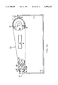
- FIG. 5 is a front isometric view of the expandable shell for changing photoconductive belts, including a mechanism for expanding and contracting the shell, installed on a belt photoconductor in an image forming apparatus;
- FIG. 6 is a back isometric view of the expandable shell for changing photoconductive belts, including a mechanism for expanding and contracting the shell, installed on a belt photoconductor in an image forming apparatus;
- FIG. 7 is a front isometric view of the mechanism for expanding and contracting the shell, printer support frame and the drive and idler rollers, having a belt photoconductor installed thereon;
- FIG. 8 is a front isometric view of the mechanism for expanding and contracting the shell, printer support frame and the drive and idler rollers, without the belt photoconductor installed;
- FIG. 9 is a front isometric view of the mechanism for expanding and contracting the shell and the drive and idler roller, without the belt photoconductor installed;
- FIG. 10 is a front view of the expandable shell for changing photoconductive belts, including a mechanism for expanding and contracting the shell, installed on a belt photoconductor in an image forming apparatus;
- FIG. 11 is a front isometric view of the mechanism for expanding and contracting the shell, printer support frame and the drive and idler rollers, having a belt photoconductor installed thereon;
- FIG. 12 is a front isometric view of the mechanism for expanding and contracting the shell and the drive and idler roller, without the belt photoconductor installed.
- Expandable shell 10 is formed to closely conform to the shape of a photoconductor belt 1 when belt 1 is installed over the drive roller 3 and the idler roller 4 in an image forming apparatus, such as a laser printer.
- this shape has rounded ends, one of a smaller diameter than the other, with top and bottom panels, 11 and 12, connecting the two ends to form a tapered construction.
- expandable shell 10 is a two piece construction manufactured by injection molding a suitable plastic material such as polyethylene. It should be noted that other materials, constructions and methods of manufacture can be employed.
- Large radius rounded end 17 is slidably attached to top panel 11 and bottom panel 12 between an expanded position, such as that shown in FIGS. 4A and 4E, and a contracted position, such as that shown in FIGS. 4B and 4D. This is accomplished by expansion nub slots 20, formed in straight expansion flanges 18 on rounded end 17.
- the two straight expansion flanges 18 on rounded end 17 are formed along diametrically opposed edges of the cylindrical section which constitutes the main body of rounded end 17.
- Expansion nub slots 20 are sized and positioned to slidably receive expansion nubs 19, which protrude outward from a straight expansion flange 18 on bottom panel 12 and a tapered expansion flange 15 on top panel 11.
- a slight downward flexing of top panel 11 is required to snap rounded end 17 onto the main shell body, formed by top panel 11, bottom panel 12, small radius rounded end 13 and front panel 16.
- Front panel 16 spans between the two front edges of top panel 11 and bottom panel 12 and connects the two panels to form a rigid structure.
- a flex relief slot 14 is formed part way along the connection between front panel 16 and top panel 11 at the end of front panel 11 which has the tapered expansion flange 15.
- Relief slot 14 in conjunction with tapered flange 15, operates to constrict shell 10 around belt photoconductor 1 when rounded end 17 is forced into its contracted position.
- a handle 36 is formed on front panel 16 to facilitate installation and removal of shell 10 on and from a belt photoconductor in an image forming apparatus.
- a pair of rails 21 are formed along the length of both small radius rounded end 13 and large radius rounded end 17.
- Rails 21 run along lines parallel to the axes of the arcuate sections of rounded ends 13 and 17 and lines which approximately bisect the cylindrical sections. Actually, the line defining the rail formed on large radius end 17 intersects the arc at a point slightly less than 0°, while the line defining the rail formed on the small radius end intersects that arc at a point slightly less than 180°.
- This positioning of rails 21 compensates for the fact that when shell 10 is installed on a belt in an image forming apparatus, bottom panel 12 is essentially horizontal, which is, here, also the direction of expansion and contraction.
- the cross sections of rails 21 are here generally "T” shaped to matingly engage stationary shell guide 22 and slidable shell guide 23.
- the cross-sectional shapes of rails 21 can be varied, for instance, using an "L” shape or a dove tail shape, with corresponding alterations in the guide slots of stationary shell guide 22 and slidable shell guide 23.
- shell 10 Additional modifications to shell 10 can be implemented, including the positioning of rails 21 along lines which don't necessarily bisect the cylindrical sections, or providing multiple or single shorter rails.
- the rails could be single or multiple mushroom shaped, or similar shaped, pins.
- the radii of rounded ends 13 and 17 is dependent upon the radii of idler roller 4 and drive roller 3, respectively.
- a tapered flange and flex relief slot can be provided on bottom panel 12 if desired.
- a small ridge can be formed to circumvolve the inner marginal back edge of the housing to interact with the back edge of the belt and facilitate belt removal. Other modifications are possible.
- One possible mechanism for expanding and contracting expandable shell 10 uses a fixed or stationary shell guide 22 and a movable shell guide or slidable shell guide 23 in connection with an idler roller 4 which is movable toward drive roller 3 to facilitate belt installation and removal.
- slidable shell guide 23 is linked to idler roller 4 to move in unison with idler roller 4 causing shell 10 to contract and expand.
- Stationary shell guide 22 is fixed to printer support frame 2 at a point along the general line of expansion and contraction of shell 10.
- Slidable shell guide 23 is slidably secured within guide retainer 24, which is fixed to printer support frame 2 at an opposing point along the general line of expansion and contraction.
- Slidable shell guide 23 has a rectangular through hole 37 along its length. The cross-sectional width dimension of rectangular through hole 37 is equal to the diameter of expansion shaft 26 plus the distance required to move shell 10 from its fully expanded position to its contracted position.
- Expansion cam 25 is here generally triangular in shape.
- Cam 25 is formed off-center from the axis of rotation of shaft 26 such that the flat portion of cam 25 rests against the inner wall of rectangular through hole 37 closest to idler roller 4. A rotation of expansion shaft 26 in either direction will cause the lobe portions of cam 25 to push slidable shell guide 23 toward drive roller 3.
- An activation lever 27 is radially attached to the front end of expansion shaft 26.
- An activation pulley 28 is concentrically attached to the back end of expansion shaft 26.
- a tension belt 29 rotationally couples activation pulley 28 with a tension pulley 30, attached to the back end of tension shaft 31, for reasons which will become apparent below.
- Drive roller 3 is rigidly attached to drive shaft 5, which in turn is attached to a drive mechanism, not shown.
- Drive shaft 5 has a fixed position with respect to printer support frame 2 and will only rotate about the axis of the shaft.
- a pair of tension guide members 34 are rotatably attached around opposing ends of drive shaft 5 so that drive shaft 5 can rotate with respect to tension members 38.
- Tension guide members 34 act as slide receivers for a pair of tension slides 33.
- Tension slides 33 are rotatably attached to the ends of idler roller shaft 6 so that idler roller 4 can rotate with respect to tension slides 33.
- a pair of tension springs 35 interact between slides 33 and guides 34 to bias idler roller 4 toward the belt tension position which corresponds to the expanded position of shell 10.
- Tension shaft 31 has a tension unload cam 32 formed along a substantial portion of its length and is positioned to interact with tension slide members 34 to untension and re-tension belt 1. With both the shell and idler roller in their expanded positions, a rotation of activation lever 27 in either direction will cause belt 1 to be untensioned and shell 10 to contract in unison. A reverse rotation of activation lever 27 will re-tension belt 1 and expand shell 10.
- the old belt 1 is first removed from the printer by sliding expandable shell 10 into the printer, with the shell in its extended position, over belt 1, as is particularly shown in FIG. 4A.
- the housing is guided by rails 21 and shell guides 22 and 23.
- shell 10 completely surrounds belt 1 but does not touch it.
- Belt 1 is then untensioned by moving idler 4 roller towards drive roller 5, as is explained above.
- idler roller 4 moves to untension belt 1, shell 10 collapses in unison. This motion causes belt 1 to move from being tensioned on the rollers to being held against the inner wall of shell 10, as is shown in FIG. 4B.
- Shell 10, with the captured belt is then pulled from the printer, as is illustrated in FIG. 4C.
- the old belt photoconductor is removed from shell 10 and replaced with a new belt photoconductor.
- Shell 10 is then re-inserted into the printer as is shown in FIG. 4D.
- Belt 1 is then re-tensioned by moving idler roller 4 out and expanding shell 10 in unison, as is shown in FIG. 4E.
- Shell 10 is then removed from the printer, leaving a new photoconductive belt 1 installed in the printer, as is illustrated in FIG. 4F.
Landscapes
- Physics & Mathematics (AREA)
- General Physics & Mathematics (AREA)
- Discharging, Photosensitive Material Shape In Electrophotography (AREA)
- Electrophotography Configuration And Component (AREA)
- Control Or Security For Electrophotography (AREA)
Priority Applications (4)
| Application Number | Priority Date | Filing Date | Title |
|---|---|---|---|
| US08/163,318 US5400121A (en) | 1993-12-07 | 1993-12-07 | Belt-type photoconductor replacement apparatus |
| DE69405362T DE69405362T2 (de) | 1993-12-07 | 1994-07-14 | Gerät zum Wechseln eines photoleitfähigen Bandes |
| EP94110983A EP0657783B1 (de) | 1993-12-07 | 1994-07-14 | Gerät zum Wechseln eines photoleitfähigen Bandes |
| JP33058394A JP3575849B2 (ja) | 1993-12-07 | 1994-12-07 | ベルト型光導電体交換装置 |
Applications Claiming Priority (1)
| Application Number | Priority Date | Filing Date | Title |
|---|---|---|---|
| US08/163,318 US5400121A (en) | 1993-12-07 | 1993-12-07 | Belt-type photoconductor replacement apparatus |
Publications (1)
| Publication Number | Publication Date |
|---|---|
| US5400121A true US5400121A (en) | 1995-03-21 |
Family
ID=22589480
Family Applications (1)
| Application Number | Title | Priority Date | Filing Date |
|---|---|---|---|
| US08/163,318 Expired - Lifetime US5400121A (en) | 1993-12-07 | 1993-12-07 | Belt-type photoconductor replacement apparatus |
Country Status (4)
| Country | Link |
|---|---|
| US (1) | US5400121A (de) |
| EP (1) | EP0657783B1 (de) |
| JP (1) | JP3575849B2 (de) |
| DE (1) | DE69405362T2 (de) |
Cited By (31)
| Publication number | Priority date | Publication date | Assignee | Title |
|---|---|---|---|---|
| US5708924A (en) * | 1996-09-30 | 1998-01-13 | Xerox Corporation | Customer replaceable photoreceptor belt module |
| EP0871079A1 (de) * | 1997-04-11 | 1998-10-14 | Xerox Corporation | Klammer am Photoleiter für Transport und Einbau einer vom Benutzer wechselbaren Xerographieeinheit |
| US5909810A (en) * | 1997-12-17 | 1999-06-08 | Eastman Kodak Company | Apparatus for packaging and installation of a fusing belt |
| US5918091A (en) * | 1997-04-25 | 1999-06-29 | Nec Corporation | Endless photoreceptor belt for use in a recording device |
| US5978625A (en) * | 1997-07-16 | 1999-11-02 | Samsung Electronics Co., Ltd. | Photosensitive belt receiving case |
| US6014535A (en) * | 1998-12-10 | 2000-01-11 | Imation Corp. | Soft cartridge package for a photoreceptor belt and method of manufacturing soft cartridge package including method of loading photoreceptor belt using soft cartridge package |
| US6026274A (en) * | 1997-12-17 | 2000-02-15 | Eastman Kodak Company | Collapsible readily replaceable belt fuser assembly |
| US6044239A (en) * | 1998-07-27 | 2000-03-28 | Xerox Corporation | Molded roller with slide mechanism |
| US6049682A (en) * | 1998-12-10 | 2000-04-11 | Imation Corp. | Hard cartridge package for an organic photoreceptor belt |
| US6097912A (en) * | 1998-12-10 | 2000-08-01 | Imation Corp. | Protective cover package for an organic photoreceptor belt |
| US6167223A (en) * | 1997-04-11 | 2000-12-26 | Xerox Corporation | Photoreceptor drive module |
| US6175704B1 (en) * | 1998-05-27 | 2001-01-16 | Nec Corporation | Electrophotographic printer using replaceable photosensitive belt cartridge |
| US6185395B1 (en) * | 1999-01-18 | 2001-02-06 | Samsung Electronics Co., Ltd. | Photoreceptor web installing/removing apparatus for a printer |
| US6233415B1 (en) * | 1998-12-28 | 2001-05-15 | Samsung Elctronics Co., Ltd. | Belt cartridge in a printing apparatus |
| US6236823B1 (en) * | 1998-12-28 | 2001-05-22 | Samsung Electronics Co., Ltd. | Photosensitive belt cartridge of electrophotographic printer, photosensitive belt replacing apparatus employing the same and method thereof |
| US6308029B1 (en) * | 1999-04-13 | 2001-10-23 | Nec Corporation | Electrophotographic image forming device having an exchangeable belt and a method of exchanging the same |
| US6356725B1 (en) * | 1999-12-02 | 2002-03-12 | Samsung Electronics Co., Ltd. | Photosensitive belt cartridge of a liquid electrophotographic printer |
| US6522848B2 (en) * | 2000-08-21 | 2003-02-18 | Oki Data Corporation | Belt unit and apparatus to which belt unit is attached |
| US20030138267A1 (en) * | 2001-12-26 | 2003-07-24 | Junichi Yamazaki | Package and method of forming the package |
| US20030152400A1 (en) * | 2002-02-05 | 2003-08-14 | Stefan Maier | Device for inserting a band into a machine unit |
| US20070127955A1 (en) * | 2005-12-07 | 2007-06-07 | Tsutomu Katoh | Image forming apparatus capable of providing a stable belt movement in a belt unit |
| US20070206972A1 (en) * | 2006-03-06 | 2007-09-06 | Fuji Xerox Co., Ltd. | Protective cover, process cartridge employing same, image forming apparatus, and method of installing process cartridge |
| US20080069591A1 (en) * | 2006-09-18 | 2008-03-20 | Aetas Technology, Incorporated | Gap controlling structure for image forming apparatus |
| US20090110435A1 (en) * | 2007-10-25 | 2009-04-30 | Xerox Corporation | Belt installation tool |
| US20100015825A1 (en) * | 2008-07-18 | 2010-01-21 | Ziberna Frank J | Retractable Connector for an Electronic Device |
| US20100086327A1 (en) * | 2008-10-08 | 2010-04-08 | Xerox Corporation | System for installing a continuous belt in a marking system |
| US20100095503A1 (en) * | 2006-12-12 | 2010-04-22 | Thomas Vizjak | Device for changing a ribbon in a machine assembly |
| US20110150529A1 (en) * | 2007-08-31 | 2011-06-23 | Ohkushi Hirofumi | Belt device and image-forming apparatus |
| US20110224040A1 (en) * | 2010-03-11 | 2011-09-15 | Boissonneault Olivier | Safety guard assembly for transmission mechanisms |
| US8787797B2 (en) | 2011-10-30 | 2014-07-22 | Hewlett-Packard Development Company, L.P. | Photoconductive foil sheet applicator |
| US20150055981A1 (en) * | 2013-08-22 | 2015-02-26 | Junpei FUJITA | Image forming apparatus |
Citations (10)
| Publication number | Priority date | Publication date | Assignee | Title |
|---|---|---|---|---|
| US3888577A (en) * | 1973-02-12 | 1975-06-10 | Xerox Corp | Apparatus for packaging and subsequently installing a belt onto a roller assembly |
| US4551001A (en) * | 1982-07-20 | 1985-11-05 | Takashi Yokota | Recording apparatus using a recording member in endless belt form |
| US4655578A (en) * | 1986-03-24 | 1987-04-07 | Xerox Corporation | Reproducing apparatus cartridge mounting assembly |
| US4766455A (en) * | 1986-04-15 | 1988-08-23 | Xerox Corporation | Process unit for an imaging apparatus |
| US4804993A (en) * | 1987-08-05 | 1989-02-14 | Eastman Kodak Company | Photoconductive member mounting mechanism for an electrophotographic reproduction apparatus |
| US4811839A (en) * | 1987-12-17 | 1989-03-14 | Eastman Kodak Company | Film belt loader package |
| US4829334A (en) * | 1986-05-28 | 1989-05-09 | Mita Industrial Co., Ltd. | Image-forming machine having a cover member for covering part of an image bearing member |
| US4983146A (en) * | 1987-03-23 | 1991-01-08 | Colorocs Corporation | Belt tensioning and quick release device for electrophotographic system |
| US5243384A (en) * | 1991-03-28 | 1993-09-07 | Xerox Corporation | Customer replaceable belt module |
| US5307117A (en) * | 1992-12-08 | 1994-04-26 | Xerox Corporation | Protective shipping cover for CRU |
-
1993
- 1993-12-07 US US08/163,318 patent/US5400121A/en not_active Expired - Lifetime
-
1994
- 1994-07-14 EP EP94110983A patent/EP0657783B1/de not_active Expired - Lifetime
- 1994-07-14 DE DE69405362T patent/DE69405362T2/de not_active Expired - Fee Related
- 1994-12-07 JP JP33058394A patent/JP3575849B2/ja not_active Expired - Fee Related
Patent Citations (10)
| Publication number | Priority date | Publication date | Assignee | Title |
|---|---|---|---|---|
| US3888577A (en) * | 1973-02-12 | 1975-06-10 | Xerox Corp | Apparatus for packaging and subsequently installing a belt onto a roller assembly |
| US4551001A (en) * | 1982-07-20 | 1985-11-05 | Takashi Yokota | Recording apparatus using a recording member in endless belt form |
| US4655578A (en) * | 1986-03-24 | 1987-04-07 | Xerox Corporation | Reproducing apparatus cartridge mounting assembly |
| US4766455A (en) * | 1986-04-15 | 1988-08-23 | Xerox Corporation | Process unit for an imaging apparatus |
| US4829334A (en) * | 1986-05-28 | 1989-05-09 | Mita Industrial Co., Ltd. | Image-forming machine having a cover member for covering part of an image bearing member |
| US4983146A (en) * | 1987-03-23 | 1991-01-08 | Colorocs Corporation | Belt tensioning and quick release device for electrophotographic system |
| US4804993A (en) * | 1987-08-05 | 1989-02-14 | Eastman Kodak Company | Photoconductive member mounting mechanism for an electrophotographic reproduction apparatus |
| US4811839A (en) * | 1987-12-17 | 1989-03-14 | Eastman Kodak Company | Film belt loader package |
| US5243384A (en) * | 1991-03-28 | 1993-09-07 | Xerox Corporation | Customer replaceable belt module |
| US5307117A (en) * | 1992-12-08 | 1994-04-26 | Xerox Corporation | Protective shipping cover for CRU |
Cited By (46)
| Publication number | Priority date | Publication date | Assignee | Title |
|---|---|---|---|---|
| US5708924A (en) * | 1996-09-30 | 1998-01-13 | Xerox Corporation | Customer replaceable photoreceptor belt module |
| US6167223A (en) * | 1997-04-11 | 2000-12-26 | Xerox Corporation | Photoreceptor drive module |
| EP0871079A1 (de) * | 1997-04-11 | 1998-10-14 | Xerox Corporation | Klammer am Photoleiter für Transport und Einbau einer vom Benutzer wechselbaren Xerographieeinheit |
| US5887229A (en) * | 1997-04-11 | 1999-03-23 | Xerox Corporation | Photoreceptor shipping installation clip for xerographic customer replaceable unit (CRU) |
| US5918091A (en) * | 1997-04-25 | 1999-06-29 | Nec Corporation | Endless photoreceptor belt for use in a recording device |
| US5978625A (en) * | 1997-07-16 | 1999-11-02 | Samsung Electronics Co., Ltd. | Photosensitive belt receiving case |
| US5909810A (en) * | 1997-12-17 | 1999-06-08 | Eastman Kodak Company | Apparatus for packaging and installation of a fusing belt |
| US6026274A (en) * | 1997-12-17 | 2000-02-15 | Eastman Kodak Company | Collapsible readily replaceable belt fuser assembly |
| US6175704B1 (en) * | 1998-05-27 | 2001-01-16 | Nec Corporation | Electrophotographic printer using replaceable photosensitive belt cartridge |
| US6044239A (en) * | 1998-07-27 | 2000-03-28 | Xerox Corporation | Molded roller with slide mechanism |
| WO2000034833A1 (en) * | 1998-12-10 | 2000-06-15 | Imation Corp. | Hard cartridge package for an organic photoreceptor belt |
| US6097912A (en) * | 1998-12-10 | 2000-08-01 | Imation Corp. | Protective cover package for an organic photoreceptor belt |
| US6049682A (en) * | 1998-12-10 | 2000-04-11 | Imation Corp. | Hard cartridge package for an organic photoreceptor belt |
| US6014535A (en) * | 1998-12-10 | 2000-01-11 | Imation Corp. | Soft cartridge package for a photoreceptor belt and method of manufacturing soft cartridge package including method of loading photoreceptor belt using soft cartridge package |
| US6233415B1 (en) * | 1998-12-28 | 2001-05-15 | Samsung Elctronics Co., Ltd. | Belt cartridge in a printing apparatus |
| US6236823B1 (en) * | 1998-12-28 | 2001-05-22 | Samsung Electronics Co., Ltd. | Photosensitive belt cartridge of electrophotographic printer, photosensitive belt replacing apparatus employing the same and method thereof |
| US6185395B1 (en) * | 1999-01-18 | 2001-02-06 | Samsung Electronics Co., Ltd. | Photoreceptor web installing/removing apparatus for a printer |
| US6308029B1 (en) * | 1999-04-13 | 2001-10-23 | Nec Corporation | Electrophotographic image forming device having an exchangeable belt and a method of exchanging the same |
| US6356725B1 (en) * | 1999-12-02 | 2002-03-12 | Samsung Electronics Co., Ltd. | Photosensitive belt cartridge of a liquid electrophotographic printer |
| US6522848B2 (en) * | 2000-08-21 | 2003-02-18 | Oki Data Corporation | Belt unit and apparatus to which belt unit is attached |
| US6983840B2 (en) * | 2001-12-26 | 2006-01-10 | Ricoh Co., Ltd. | Package and method of forming the package |
| US20030138267A1 (en) * | 2001-12-26 | 2003-07-24 | Junichi Yamazaki | Package and method of forming the package |
| US7334383B2 (en) | 2001-12-26 | 2008-02-26 | Ricoh Co Ltd | Package and method of forming the package |
| US6792231B2 (en) | 2002-02-05 | 2004-09-14 | OCé PRINTING SYSTEMS GMBH | Device for inserting a band into a machine unit |
| US20030152400A1 (en) * | 2002-02-05 | 2003-08-14 | Stefan Maier | Device for inserting a band into a machine unit |
| US7627268B2 (en) * | 2005-12-07 | 2009-12-01 | Ricoh Co., Ltd. | Image forming apparatus capable of providing a stable belt movement in a belt unit |
| US20070127955A1 (en) * | 2005-12-07 | 2007-06-07 | Tsutomu Katoh | Image forming apparatus capable of providing a stable belt movement in a belt unit |
| US20070206972A1 (en) * | 2006-03-06 | 2007-09-06 | Fuji Xerox Co., Ltd. | Protective cover, process cartridge employing same, image forming apparatus, and method of installing process cartridge |
| US7532841B2 (en) * | 2006-03-06 | 2009-05-12 | Fuji Xerox Co., Ltd. | Protective cover, process cartridge employing same, image forming apparatus, and method of installing process cartridge |
| US20080069591A1 (en) * | 2006-09-18 | 2008-03-20 | Aetas Technology, Incorporated | Gap controlling structure for image forming apparatus |
| US20100095503A1 (en) * | 2006-12-12 | 2010-04-22 | Thomas Vizjak | Device for changing a ribbon in a machine assembly |
| US8453309B2 (en) * | 2006-12-12 | 2013-06-04 | OCè PRINTING SYSTEMS GMBH | Method for changing a belt in a machine assembly using a gripper having moveable opposed legs |
| US8103190B2 (en) * | 2007-08-31 | 2012-01-24 | Ricoh Company, Ltd. | Belt device and image-forming apparatus |
| US8290399B2 (en) | 2007-08-31 | 2012-10-16 | Ricoh Company, Ltd. | Belt device and image-forming apparatus |
| US20110150529A1 (en) * | 2007-08-31 | 2011-06-23 | Ohkushi Hirofumi | Belt device and image-forming apparatus |
| US7885576B2 (en) * | 2007-10-25 | 2011-02-08 | Xerox Corporation | Belt installation tool |
| US20090110435A1 (en) * | 2007-10-25 | 2009-04-30 | Xerox Corporation | Belt installation tool |
| US20100015825A1 (en) * | 2008-07-18 | 2010-01-21 | Ziberna Frank J | Retractable Connector for an Electronic Device |
| US7896676B2 (en) * | 2008-07-18 | 2011-03-01 | Bi-Link | Retractable connector for an electronic device |
| US8032054B2 (en) * | 2008-10-08 | 2011-10-04 | Xerox Corporation | System for installing a continuous belt in a marking system |
| US20100086327A1 (en) * | 2008-10-08 | 2010-04-08 | Xerox Corporation | System for installing a continuous belt in a marking system |
| US20110224040A1 (en) * | 2010-03-11 | 2011-09-15 | Boissonneault Olivier | Safety guard assembly for transmission mechanisms |
| US8790200B2 (en) | 2010-03-11 | 2014-07-29 | Les Distributions Masterfab Inc. | Safety guard assembly for transmission mechanisms |
| US8787797B2 (en) | 2011-10-30 | 2014-07-22 | Hewlett-Packard Development Company, L.P. | Photoconductive foil sheet applicator |
| US20150055981A1 (en) * | 2013-08-22 | 2015-02-26 | Junpei FUJITA | Image forming apparatus |
| US9405269B2 (en) * | 2013-08-22 | 2016-08-02 | Ricoh Company, Ltd. | Image forming apparatus with a guide member for a transfer belt |
Also Published As
| Publication number | Publication date |
|---|---|
| DE69405362D1 (de) | 1997-10-09 |
| JP3575849B2 (ja) | 2004-10-13 |
| JPH07199772A (ja) | 1995-08-04 |
| DE69405362T2 (de) | 1998-03-19 |
| EP0657783A1 (de) | 1995-06-14 |
| EP0657783B1 (de) | 1997-09-03 |
Similar Documents
| Publication | Publication Date | Title |
|---|---|---|
| US5400121A (en) | Belt-type photoconductor replacement apparatus | |
| DE3587456T2 (de) | Elektrostatisches Kopiergerät. | |
| CA1122645A (en) | Belt support and steering module | |
| DE60103461T2 (de) | Bandantrieb und Bilderzeugungsapparat mit Bandantrieb | |
| DE3504939C2 (de) | ||
| EP0405514A2 (de) | Bilderzeugungsgerät | |
| US5669054A (en) | Multi-directional driving mechanism and transfer device for an image forming machine using such mechanism | |
| US5070365A (en) | Low lateral force drive roller system | |
| DE2008194C3 (de) | Elektrophotographisches Kopiergerät | |
| US20220019161A1 (en) | Imaging system | |
| US5574550A (en) | Transfer device for image forming machine | |
| US6233415B1 (en) | Belt cartridge in a printing apparatus | |
| US7300015B2 (en) | Paper magazine | |
| US5602634A (en) | Transfer device of image forming machine | |
| US11422487B2 (en) | Imaging system | |
| CA1058686A (en) | Belt type sensitive member unit | |
| CA1095579A (en) | Xerographic copier | |
| US4866485A (en) | Molded skive and guide | |
| CA1203560A (en) | Belt support and steering roller | |
| EP0191590B1 (de) | Bahnträger und Führungsrolle | |
| US6356725B1 (en) | Photosensitive belt cartridge of a liquid electrophotographic printer | |
| JPS6315238Y2 (de) | ||
| US5474220A (en) | Successive sheet feed mechanism | |
| JPH09156794A (ja) | 用紙搬送用ベルトのクリーニング装置 | |
| JPH04190280A (ja) | シームレスベルト状感光体における寄り止め機構 |
Legal Events
| Date | Code | Title | Description |
|---|---|---|---|
| AS | Assignment |
Owner name: HEWLETT-PACKARD COMPANY, CALIFORNIA Free format text: ASSIGNMENT OF ASSIGNORS INTEREST;ASSIGNOR:FOOTE, WAYNE E.;REEL/FRAME:006836/0871 Effective date: 19931207 |
|
| STCF | Information on status: patent grant |
Free format text: PATENTED CASE |
|
| FEPP | Fee payment procedure |
Free format text: PAYOR NUMBER ASSIGNED (ORIGINAL EVENT CODE: ASPN); ENTITY STATUS OF PATENT OWNER: LARGE ENTITY |
|
| FPAY | Fee payment |
Year of fee payment: 4 |
|
| AS | Assignment |
Owner name: HEWLETT-PACKARD COMPANY, COLORADO Free format text: MERGER;ASSIGNOR:HEWLETT-PACKARD COMPANY;REEL/FRAME:011523/0469 Effective date: 19980520 |
|
| FPAY | Fee payment |
Year of fee payment: 8 |
|
| REMI | Maintenance fee reminder mailed | ||
| REMI | Maintenance fee reminder mailed | ||
| FPAY | Fee payment |
Year of fee payment: 12 |
|
| SULP | Surcharge for late payment |
Year of fee payment: 11 |
|
| AS | Assignment |
Owner name: HEWLETT-PACKARD DEVELOPMENT COMPANY, L.P., TEXAS Free format text: ASSIGNMENT OF ASSIGNORS INTEREST;ASSIGNOR:HEWLETT-PACKARD COMPANY;REEL/FRAME:026945/0699 Effective date: 20030131 |