US5384556A - Microwave circulator apparatus and method - Google Patents
Microwave circulator apparatus and method Download PDFInfo
- Publication number
- US5384556A US5384556A US08/129,709 US12970993A US5384556A US 5384556 A US5384556 A US 5384556A US 12970993 A US12970993 A US 12970993A US 5384556 A US5384556 A US 5384556A
- Authority
- US
- United States
- Prior art keywords
- disk
- housing
- circulator
- providing
- center conductor
- Prior art date
- Legal status (The legal status is an assumption and is not a legal conclusion. Google has not performed a legal analysis and makes no representation as to the accuracy of the status listed.)
- Expired - Fee Related
Links
- 238000000034 method Methods 0.000 title claims description 9
- 229910000859 α-Fe Inorganic materials 0.000 claims abstract description 42
- 239000004020 conductor Substances 0.000 claims abstract description 30
- 230000006835 compression Effects 0.000 claims abstract description 11
- 238000007906 compression Methods 0.000 claims abstract description 11
- 239000002184 metal Substances 0.000 claims abstract description 7
- 229910052751 metal Inorganic materials 0.000 claims abstract description 7
- 239000000463 material Substances 0.000 claims description 12
- 230000009471 action Effects 0.000 claims description 9
- RYGMFSIKBFXOCR-UHFFFAOYSA-N Copper Chemical compound [Cu] RYGMFSIKBFXOCR-UHFFFAOYSA-N 0.000 claims description 6
- 229910052802 copper Inorganic materials 0.000 claims description 5
- 239000010949 copper Substances 0.000 claims description 5
- 239000003989 dielectric material Substances 0.000 claims description 5
- 238000005530 etching Methods 0.000 claims description 2
- 239000004593 Epoxy Substances 0.000 description 3
- 230000005540 biological transmission Effects 0.000 description 3
- PXHVJJICTQNCMI-UHFFFAOYSA-N Nickel Chemical compound [Ni] PXHVJJICTQNCMI-UHFFFAOYSA-N 0.000 description 2
- 239000000919 ceramic Substances 0.000 description 2
- 238000010276 construction Methods 0.000 description 2
- 238000004519 manufacturing process Methods 0.000 description 2
- 229910000679 solder Inorganic materials 0.000 description 2
- 238000005476 soldering Methods 0.000 description 2
- 229910000831 Steel Inorganic materials 0.000 description 1
- 230000004075 alteration Effects 0.000 description 1
- 239000010960 cold rolled steel Substances 0.000 description 1
- 239000011889 copper foil Substances 0.000 description 1
- 230000000694 effects Effects 0.000 description 1
- PCHJSUWPFVWCPO-UHFFFAOYSA-N gold Chemical compound [Au] PCHJSUWPFVWCPO-UHFFFAOYSA-N 0.000 description 1
- 239000010931 gold Substances 0.000 description 1
- 229910052737 gold Inorganic materials 0.000 description 1
- 230000008676 import Effects 0.000 description 1
- 238000009434 installation Methods 0.000 description 1
- 230000003993 interaction Effects 0.000 description 1
- 230000005415 magnetization Effects 0.000 description 1
- 238000012986 modification Methods 0.000 description 1
- 230000004048 modification Effects 0.000 description 1
- 229910052759 nickel Inorganic materials 0.000 description 1
- 230000009467 reduction Effects 0.000 description 1
- 239000007787 solid Substances 0.000 description 1
- 239000010959 steel Substances 0.000 description 1
Images


Classifications
-
- H—ELECTRICITY
- H01—ELECTRIC ELEMENTS
- H01P—WAVEGUIDES; RESONATORS, LINES, OR OTHER DEVICES OF THE WAVEGUIDE TYPE
- H01P1/00—Auxiliary devices
- H01P1/32—Non-reciprocal transmission devices
- H01P1/38—Circulators
- H01P1/383—Junction circulators, e.g. Y-circulators
- H01P1/387—Strip line circulators
Definitions
- This invention relates generally to microwave devices and in particular to a method and apparatus for assembling a low cost ferrite stripline circulator.
- non-reciprocal devices such as circulators and isolators.
- energy fed to an input port of the circulator is transferred to an output port of the circulator, whereas input energy fed to the output port of the circulator is not efficiently transferred to the input port of the circulator, and therefore, such a device is generally referred to as a non-reciprocal device.
- Such devices are used to minimize VSWR interactions between adjacent components or to duplex a common antenna between a transmitter and a receiver.
- junction circulator which can be comprised of either a stripline transmission medium or microstrip transmission medium.
- the construction of a stripline circulator is shown in Microwave Circulator Design, Douglas K. Linkhart, Artech House, Inc., MA 1989, pages 37-39.
- a junction circulator typically comprises three ports and is generally referred to in the art as a Y-junction circulator.
- the basic construction of a stripline Y-junction circulator includes a center conductor having three stripline branches connected to a center portion. The center conductor is sandwiched between a pair of ferrite disks which space said center conductor from ground planes disposed over the second surfaces of the ferrite disks.
- the ferrites are used to provide nonreciprocal performance via gyromagnetic action.
- Input energy fed to an input one of the branches of the circulator is transferred either to a clockwise disposed or counter-clockwise disposed adjacent output port of the circulator in accordance with the polarity of the magnetic field fed through the ferrite disks.
- Screw clamps, soldering or epoxy techniques usually hold the circulators together and in place.
- It is a further object of this invention to provide a microwave circulator comprising a housing means for supporting a plurality of elements of the circulator, first disk means disposed within the housing means for providing gyromagnetic action, center conductor means disposed on the first disk means, the center conductor means having a plurality of tabs, each of the tabs extending outside the housing means for providing ports for circuit connections, second disk means disposed on the center conductor means for providing the gyromagnetic action, a ground plane disposed on the second disk means, the circumference of the ground plane contacting the sides of the housing means, a magnet disposed on the ground plane, cover means disposed on top of the magnet for providing magnetic shielding, and means disposed on the cover means for compressing the plurality of elements disposed within the housing means.
- the housing means comprises a metal cylinder having a closed base, or the housing means comprises a metal cylinder having a closed base with a flange extending beyond the circumference of the cylinder walls for mounting the circulator.
- the first disk means and the second disk means comprises a ferrite material.
- the first disk means and the second disk means each comprises a ring having an inner portion comprising a ferrite material and an outer portion comprising a dielectric material.
- the center conductor means comprises a photochemically etched copper.
- the compressing means comprises spring means disposed on the cover means for providing a compression force to the plurality of elements of the circulator, and retainer means disposed on the spring means and positioned within a groove of the housing means for compressing the spring means.
- It is a further object of this invention to provide a method for providing a low cost microwave circulator comprising the steps of providing a housing means for supporting a plurality of elements of the circulator, disposing a first disk means within the housing means adjacent to a bottom surface of the housing means for providing gyromagnetic action, disposing on the first ferrite disk means a center conductor means, the center conductor means having a plurality of tabs, each of the tabs extending outside the housing means for providing ports for circuit connection, disposing a second disk means on the center conductor for providing the gyromagnetic action, disposing a ground plane on the second disk means, the circumference of the ground plane being in contact with the sides of the housing means, positioning a magnet on the ground plane, placing a cover means on top of the magnet for magnetic shielding, and compressing the plurality of elements disposed within the housing means with means disposed on the cover means.
- the steps of disposing the first disk means and the second disk means in the housing means includes the first disk means and the second disk means each comprising ferrite material.
- the step of disposing the first disk means and the second disk means in the housing means includes the first disk means and the second disk means each comprises a ring having an inner portion comprising a ferrite material and an outer portion comprising a dielectric material.
- the step of disposing on the first ferrite disk a center conductor means comprises the step of photochemically etching copper to obtain the center conductor.
- the step of comprising the plurality of elements comprises the steps of disposing a spring means on the cover means for providing a compression force to the plurality of elements, and positioning a retainer means on the spring means and within a groove of the housing means for compressing the spring means.
- FIG. 1 is an exploded perspective of a ferrite stripline circulator according to the present invention showing the elements of said circulator;
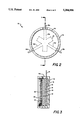
- FIG. 2 is a plan view of a ferrite stripline circulator according to the present invention.
- FIG. 3 is a cross-sectional view along line A--A of the ferrite stripline circulator of FIG. 2;
- FIG. 4 is a plan view of an alternate embodiment of the invention showing a base with a rectangular flange and ferrite disk having a ferrite center portion surrounded by a dielectric ring outer portion;
- FIG. 5 is a cross-sectional view along line B--B of the alternate embodiment of FIG. 4;
- FIG. 6 is a plan view of the ferrite disk of the alternate embodiment shown in FIG. 5.
- the circulator 10 comprises a housing 12 having a center conductor 16 sandwiched between two ferrite disks 14 and 18, a ground plane 20 disposed on the upper ferrite disk 18, a magnet 22 disposed on the ground plane 22, a cover 24 on top of the magnet 22, a compression spring 26 disposed on the cover 24, and a C-clip 28 inserted in a groove 30 on the upper inner circumference of the housing 12.
- FIG. 2 a plan view of a center conductor 16 used in the circulator 10 is shown.
- the center conductor 16 is photochemically etched without tight tolerances.
- the circulator 10 has three ports formed by three extension arms 16a-16c of the center conductor having tabs 32a-32c extending through slot openings 13a-13c in the cylindrical surface of the housing 12.
- the tabs 32a-32c facilitate soldering the circulator 10 into either a microstrip or stripline microwave printed circuit board.
- the housing 12 is a low cost, nickel plated, steel screw machine part cylindrical in shape and having three slot openings 13a-13c spaced at 120° intervals around the cylinder walls (13b and 13c are not shown).
- the ferrite disks 14, 18 are simple round disks having a diameter of 0.750 ⁇ 0.003 inches and a height of 0.045 ⁇ 0.005 inches which do not require a tight tolerance on the thickness dimension because the compression spring 26 absorbs tolerance effects.
- the center conductor 16 is photochemically etched from copper foil 0.005 inches thick.
- the ground plane 20 is a stamped metal piece of copper which folds up and contacts the wall of the cylindrical housing 12 over a large contact area. Both the center conductor 16 and the ground plane 20 are gold plated.
- the magnet 22 is circular shape with a diameter of 0.700 ⁇ 0.010 inches and thickness of 0.050 ⁇ 0.005 inches.
- the cover 24 is made of nickle plated cold rolled steel and is circular. The cover could be omitted in applications which allow some magnetic field to be created by the magnet 22.
- the compression spring 26 is disposed on the cover 24 and embodied by Part No. 9714K55 manufactured by McMaster-Carr Corporation of Alanta, Ga.
- the C-clip is embodied by Part No. 98409A181 manufactured by McMaster-Carr Corporation of Atlanta, Ga.
- the circulator 10 is assembled without any epoxy bonding, solder joints or conventional fasteners and results in a circulator 10 that is easily disassembled and reworked without damage to the piece parts used in the circulator 10.
- Other relevant parameters of circulator 19 are given in Table 1.
- FIG. 4 an alternate embodiment of the invention is shown which comprises a different configuration for enabling the installation of a circulator 50 in an application requiring a housing 52 to have a rectangular base portion with four mounting holes 74a-74d.
- the outside dimensions of the rectangular base portion of housing 50 are 1.00 inches long by 0.85 inches wide.
- the four mounting holes 74a-74d are located at the four corners.
- the upper portion of the housing 52 is cylindrical having the same dimensions as the housing 12 in FIG. 2.
- the center conductor 56 has extension arms 56a-56c and two of such arms 56b and 56c are angled at the cylindrical wall of housing 52 to permit the tabs 72b and 72c to protrude through slot openings 53b and 53c in the cylindrical walls of the housing 52 equally spaced at 120° intervals.
- the extension arm 56a comprises tab 72a which protrudes straight through its slot opening 53a in the cylindrical wall.
- This alternate embodiment further comprises a C-clip 68 (not shown) which is inserted in a groove 70 on the upper inner circumference of the cylindrical portion of housing 52 to assure proper operation of the stacked components in conjunction with a compression spring 66 (not shown).
- FIG. 5 shows a cross-sectional view along line B--B in FIG. 4 of the alternate embodiment.
- the housing 52 comprises a center conductor 56 sandwiched between two ferrite disks 54, 58, a ground plane 60 disposed on the upper ferrite disk 58, a magnet 62 disposed on the ground plane 60, a cover 64 disposed on top of the magnet 62, a compression spring 66 disposed on the cover 64, and a C-clip 68 inserted in, the groove 70 on the upper inner circumference of the housing 52.
- FIG. 6 is a plan view of one of the ferrite disks 54, 58.
- the ferrite disks 54, 58 in the alternate embodiment comprises a circular ferrite material 54b within a dielectric ring 54a.
- the ferrite material 54b has a diameter of 0.493 inches and the diameter of the complete ferrite disk 54, 58 is 0.75 inches.
- the dielectric ring 54a of the ferrite disks 54, 58 is embodied with Model MCT-20 ceramic from Trans-Tech of Adamstown, Md. This type of ferrite disk 54, 58 in a circulator 50 results in reduced losses for broadband applications. Other relevant parameters of circulator 50 are the same as in Table 1.
Landscapes
- Non-Reversible Transmitting Devices (AREA)
Abstract
A ferrite stripline circulator having low cost, broad tolerance elements and an easy to assembly design. The unit comprises of a cylindrical housing into which are stacked a ferrite disk, a center conductor, another ferrite disk, a metal ground plane, a disk magnet, a metal cover and a compression spring. A C-clip, that fits into a groove on an upper inner circumference of the cylinder, forces the compression spring against the cover and thereby applies the pressure that is required to assure proper operation of the stacked elements.
Description
This invention relates generally to microwave devices and in particular to a method and apparatus for assembling a low cost ferrite stripline circulator.
As is known in the art, energy transfer between two or more ports may be provided by non-reciprocal devices such as circulators and isolators. In particular with circulators, energy fed to an input port of the circulator is transferred to an output port of the circulator, whereas input energy fed to the output port of the circulator is not efficiently transferred to the input port of the circulator, and therefore, such a device is generally referred to as a non-reciprocal device. Such devices are used to minimize VSWR interactions between adjacent components or to duplex a common antenna between a transmitter and a receiver.
One type of circulator commonly employed in the art is a junction circulator which can be comprised of either a stripline transmission medium or microstrip transmission medium. The construction of a stripline circulator is shown in Microwave Circulator Design, Douglas K. Linkhart, Artech House, Inc., MA 1989, pages 37-39. A junction circulator typically comprises three ports and is generally referred to in the art as a Y-junction circulator. The basic construction of a stripline Y-junction circulator includes a center conductor having three stripline branches connected to a center portion. The center conductor is sandwiched between a pair of ferrite disks which space said center conductor from ground planes disposed over the second surfaces of the ferrite disks. Disposed over the second surfaces of the ground planes are permanent magnets which magnetically bias the ferrite. The ferrites are used to provide nonreciprocal performance via gyromagnetic action. Input energy fed to an input one of the branches of the circulator is transferred either to a clockwise disposed or counter-clockwise disposed adjacent output port of the circulator in accordance with the polarity of the magnetic field fed through the ferrite disks. Screw clamps, soldering or epoxy techniques usually hold the circulators together and in place.
Many microwave systems require ferrite circulators with stripline, microstrip or coaxial transmission line interfaces. Solid state phased array systems require large quantities of circulators (typically one to three per transmit/receive (T/R) module. In order to reduce system costs components that are used repetitively such as circulators are key targets for cost reduction. Prior art circulators have been implemented with solder joints, epoxy bonds or conventional fasteners which contribute to the circulator cost and they are not easily disassembled for rework without damage to the parts in a unit. Accordingly, there is a need for a simply assembled, low cost microwave ferrite circulator.
Accordingly, it is therefore an object of this invention to provide a low cost stripline circulator suitable for low, moderate or high volume production.
It is a further object of this invention to provide a low cost method for assembling a stripline circulator suitable for low, moderate or high volume production.
It is a further object of this invention to provide a microwave circulator comprising a housing means for supporting a plurality of elements of the circulator, first disk means disposed within the housing means for providing gyromagnetic action, center conductor means disposed on the first disk means, the center conductor means having a plurality of tabs, each of the tabs extending outside the housing means for providing ports for circuit connections, second disk means disposed on the center conductor means for providing the gyromagnetic action, a ground plane disposed on the second disk means, the circumference of the ground plane contacting the sides of the housing means, a magnet disposed on the ground plane, cover means disposed on top of the magnet for providing magnetic shielding, and means disposed on the cover means for compressing the plurality of elements disposed within the housing means. The housing means comprises a metal cylinder having a closed base, or the housing means comprises a metal cylinder having a closed base with a flange extending beyond the circumference of the cylinder walls for mounting the circulator. The first disk means and the second disk means comprises a ferrite material. The first disk means and the second disk means each comprises a ring having an inner portion comprising a ferrite material and an outer portion comprising a dielectric material. The center conductor means comprises a photochemically etched copper. The compressing means comprises spring means disposed on the cover means for providing a compression force to the plurality of elements of the circulator, and retainer means disposed on the spring means and positioned within a groove of the housing means for compressing the spring means.
It is a further object of this invention to provide a method for providing a low cost microwave circulator comprising the steps of providing a housing means for supporting a plurality of elements of the circulator, disposing a first disk means within the housing means adjacent to a bottom surface of the housing means for providing gyromagnetic action, disposing on the first ferrite disk means a center conductor means, the center conductor means having a plurality of tabs, each of the tabs extending outside the housing means for providing ports for circuit connection, disposing a second disk means on the center conductor for providing the gyromagnetic action, disposing a ground plane on the second disk means, the circumference of the ground plane being in contact with the sides of the housing means, positioning a magnet on the ground plane, placing a cover means on top of the magnet for magnetic shielding, and compressing the plurality of elements disposed within the housing means with means disposed on the cover means. The steps of disposing the first disk means and the second disk means in the housing means includes the first disk means and the second disk means each comprising ferrite material. The step of disposing the first disk means and the second disk means in the housing means includes the first disk means and the second disk means each comprises a ring having an inner portion comprising a ferrite material and an outer portion comprising a dielectric material. The step of disposing on the first ferrite disk a center conductor means comprises the step of photochemically etching copper to obtain the center conductor. The step of comprising the plurality of elements comprises the steps of disposing a spring means on the cover means for providing a compression force to the plurality of elements, and positioning a retainer means on the spring means and within a groove of the housing means for compressing the spring means.
Other and further features and advantages of the invention will become apparent in connection with the accompanying drawings wherein:
FIG. 1 is an exploded perspective of a ferrite stripline circulator according to the present invention showing the elements of said circulator;
FIG. 2 is a plan view of a ferrite stripline circulator according to the present invention;
FIG. 3 is a cross-sectional view along line A--A of the ferrite stripline circulator of FIG. 2;
FIG. 4 is a plan view of an alternate embodiment of the invention showing a base with a rectangular flange and ferrite disk having a ferrite center portion surrounded by a dielectric ring outer portion; and
FIG. 5 is a cross-sectional view along line B--B of the alternate embodiment of FIG. 4; and
FIG. 6 is a plan view of the ferrite disk of the alternate embodiment shown in FIG. 5.
Referring to FIG. 1 an exploded perspective view of a low cost stripline circulator 10 is shown. The circulator 10 comprises a housing 12 having a center conductor 16 sandwiched between two ferrite disks 14 and 18, a ground plane 20 disposed on the upper ferrite disk 18, a magnet 22 disposed on the ground plane 22, a cover 24 on top of the magnet 22, a compression spring 26 disposed on the cover 24, and a C-clip 28 inserted in a groove 30 on the upper inner circumference of the housing 12.
Referring now to FIG. 2, a plan view of a center conductor 16 used in the circulator 10 is shown. The center conductor 16 is photochemically etched without tight tolerances. The circulator 10 has three ports formed by three extension arms 16a-16c of the center conductor having tabs 32a-32c extending through slot openings 13a-13c in the cylindrical surface of the housing 12. The tabs 32a-32c facilitate soldering the circulator 10 into either a microstrip or stripline microwave printed circuit board.
Referring now to FIG. 3, a cross-sectional view along line A--A of the circulator in FIG. 2 is shown. The housing 12 is a low cost, nickel plated, steel screw machine part cylindrical in shape and having three slot openings 13a-13c spaced at 120° intervals around the cylinder walls (13b and 13c are not shown). The ferrite disks 14, 18 are simple round disks having a diameter of 0.750±0.003 inches and a height of 0.045±0.005 inches which do not require a tight tolerance on the thickness dimension because the compression spring 26 absorbs tolerance effects. The center conductor 16 is photochemically etched from copper foil 0.005 inches thick. The ground plane 20 is a stamped metal piece of copper which folds up and contacts the wall of the cylindrical housing 12 over a large contact area. Both the center conductor 16 and the ground plane 20 are gold plated. The magnet 22 is circular shape with a diameter of 0.700±0.010 inches and thickness of 0.050±0.005 inches. The cover 24 is made of nickle plated cold rolled steel and is circular. The cover could be omitted in applications which allow some magnetic field to be created by the magnet 22. The compression spring 26 is disposed on the cover 24 and embodied by Part No. 9714K55 manufactured by McMaster-Carr Corporation of Alanta, Ga. The C-clip is embodied by Part No. 98409A181 manufactured by McMaster-Carr Corporation of Atlanta, Ga. Of particular import is that the circulator 10 is assembled without any epoxy bonding, solder joints or conventional fasteners and results in a circulator 10 that is easily disassembled and reworked without damage to the piece parts used in the circulator 10. Other relevant parameters of circulator 19 are given in Table 1.
              TABLE 1
______________________________________
Property               Value
______________________________________
Ferrite material       64260
Dielectric constant of Ferrite
                       15.4
Saturation magnetization
                       550 Gauss
Center frequency       3.3 GHz
Stripline height       0.090 inches
Dielectric constant of ring
                       20
Magnet Material        Ceramic 5
Dielectric Material    MCT 20
Curie temperature of ferrite
                       280°
3 dB line width        100 Oe
______________________________________
Referring now to FIG. 4 an alternate embodiment of the invention is shown which comprises a different configuration for enabling the installation of a circulator 50 in an application requiring a housing 52 to have a rectangular base portion with four mounting holes 74a-74d. The outside dimensions of the rectangular base portion of housing 50 are 1.00 inches long by 0.85 inches wide. The four mounting holes 74a-74d are located at the four corners. The upper portion of the housing 52 is cylindrical having the same dimensions as the housing 12 in FIG. 2. The center conductor 56 has extension arms 56a-56c and two of such arms 56b and 56c are angled at the cylindrical wall of housing 52 to permit the tabs 72b and 72c to protrude through slot openings 53b and 53c in the cylindrical walls of the housing 52 equally spaced at 120° intervals. The extension arm 56a comprises tab 72a which protrudes straight through its slot opening 53a in the cylindrical wall. This alternate embodiment further comprises a C-clip 68 (not shown) which is inserted in a groove 70 on the upper inner circumference of the cylindrical portion of housing 52 to assure proper operation of the stacked components in conjunction with a compression spring 66 (not shown).
Referring to FIG. 5 and FIG. 6, FIG. 5 shows a cross-sectional view along line B--B in FIG. 4 of the alternate embodiment. The housing 52 comprises a center conductor 56 sandwiched between two ferrite disks 54, 58, a ground plane 60 disposed on the upper ferrite disk 58, a magnet 62 disposed on the ground plane 60, a cover 64 disposed on top of the magnet 62, a compression spring 66 disposed on the cover 64, and a C-clip 68 inserted in, the groove 70 on the upper inner circumference of the housing 52. FIG. 6 is a plan view of one of the ferrite disks 54, 58. The ferrite disks 54, 58 in the alternate embodiment comprises a circular ferrite material 54b within a dielectric ring 54a. The ferrite material 54b has a diameter of 0.493 inches and the diameter of the complete ferrite disk 54, 58 is 0.75 inches. The dielectric ring 54a of the ferrite disks 54, 58 is embodied with Model MCT-20 ceramic from Trans-Tech of Adamstown, Md. This type of ferrite disk 54, 58 in a circulator 50 results in reduced losses for broadband applications. Other relevant parameters of circulator 50 are the same as in Table 1.
This concludes the description of the preferred embodiment. However, many modifications and alterations will be obvious to one of ordinary skill in the art without departing from the spirit and scope of the inventive concept. Therefore, it is intended that the scope of this invention be limited only by the appended claims.
Claims (10)
1. A microwave circulator comprising:
a housing means for supporting a plurality of elements of said circulator;
first disk means disposed within said housing means for providing gyromagnetic action;
center conductor means disposed on said first disk means, said center conductor means having a plurality of tabs, each of said tabs extending outside said housing means for providing ports for circuit connections;
second disk means disposed on said center conductor means for providing said gyromagnetic action;
a ground plane disposed on said second disk means, the circumference of said ground plane contacting the sides of said housing means;
a magnet disposed on said ground plane;
cover means disposed on top of said magnet for providing magnetic shielding;
spring means disposed on said cover means for providing a compression force to said plurality of elements of said circulator; and
retainer means disposed on said spring means and positioned within a groove of said housing means for compressing said spring means.
2. The microwave circulator as recited in claim 1 wherein said housing means comprises a metal cylinder having a closed base.
3. The microwave circulator as recited in claim 1 wherein said housing means comprises a metal cylinder having a closed base with a flange extending beyond the circumference of said cylinder walls for mounting said circulator.
4. The microwave circulator as recited in claim 1 wherein said first disk means and said second disk means comprises a ferrite material.
5. The microwave circulator as recited in claim 1 wherein said first disk means and said second disk means each comprises a ring having an inner portion comprising a ferrite material and an outer portion comprising a dielectric material.
6. The microwave circulator as recited in claim 1 wherein said center conductor means comprises a photochemically etched copper.
7. A method for providing a low cost microwave circulator comprising the steps of:
providing a housing means for supporting a plurality of elements of said circulator;
disposing a first disk means within said housing means adjacent to a bottom surface of said housing means for providing gyromagnetic action;
disposing on said first disk means a center conductor means, said center conductor means having a plurality of tabs, each of said tabs extending outside said housing means for providing ports for circuit connection;
disposing a second disk means on said center conductor for providing said gyromagnetic action;
disposing a ground plane on said second disk means, the circumference of said ground plane being in contact with the sides of said housing means;
positioning a magnet on said ground plane;
placing a cover means on top of said magnet for magnetic shielding;
disposing a spring means on said cover means for providing a compression force to said plurality of elements; and
positioning a retainer means on said spring means and within a groove of said housing means for compressing said spring means.
8. The method as recited in claim 7 wherein said steps of disposing said first disk means and said second disk means in said housing means includes the step of said first disk means and said second disk means each comprising ferrite material.
9. The method as recited in claim 7 wherein said step of disposing said first disk means and said second disk means in said housing means includes the step of said first disk means and said second disk means each comprises a ring having an inner portion comprising a ferrite material and an outer portion comprising a dielectric material.
10. The method as recited in claim 7 wherein said step of disposing on said first disk a center conductor means comprises the step of photochemically etching copper to obtain said center conductor.
Priority Applications (1)
| Application Number | Priority Date | Filing Date | Title |
|---|---|---|---|
| US08/129,709 US5384556A (en) | 1993-09-30 | 1993-09-30 | Microwave circulator apparatus and method |
Applications Claiming Priority (1)
| Application Number | Priority Date | Filing Date | Title |
|---|---|---|---|
| US08/129,709 US5384556A (en) | 1993-09-30 | 1993-09-30 | Microwave circulator apparatus and method |
Publications (1)
| Publication Number | Publication Date |
|---|---|
| US5384556A true US5384556A (en) | 1995-01-24 |
Family
ID=22441218
Family Applications (1)
| Application Number | Title | Priority Date | Filing Date |
|---|---|---|---|
| US08/129,709 Expired - Fee Related US5384556A (en) | 1993-09-30 | 1993-09-30 | Microwave circulator apparatus and method |
Country Status (1)
| Country | Link |
|---|---|
| US (1) | US5384556A (en) |
Cited By (12)
| Publication number | Priority date | Publication date | Assignee | Title |
|---|---|---|---|---|
| US5653841A (en) * | 1995-04-13 | 1997-08-05 | Martin Marietta Corporation | Fabrication of compact magnetic circulator components in microwave packages using high density interconnections |
| US6107895A (en) * | 1996-04-03 | 2000-08-22 | Deltec Telesystems International Limited | Circulator and components thereof |
| KR100311816B1 (en) * | 1999-08-03 | 2001-11-03 | 이형도 | Cirulator |
| US6625869B2 (en) * | 2000-05-30 | 2003-09-30 | Murata Manufacturing Co., Ltd. | Method for manufacturing nonreciprocal circuit device |
| KR100457061B1 (en) * | 2001-11-17 | 2004-11-18 | 케이에스엠 주식회사 | Isolator |
| US20060017520A1 (en) * | 2004-07-20 | 2006-01-26 | Kingston James P | Ferrite circulator having alignment members |
| CN100348545C (en) * | 2005-11-25 | 2007-11-14 | 长沙隆泰科技有限公司 | Process for microwave sintering gyromagnet ferrite material |
| US7385454B2 (en) | 2005-05-23 | 2008-06-10 | M/A-Com, Inc. | Ferrite housing for microwave devices |
| EP2131442A1 (en) * | 2008-06-06 | 2009-12-09 | Smiths Group PLC | Microwave circulators |
| US20100102896A1 (en) * | 2008-10-28 | 2010-04-29 | Hitachi Global Storage Technologies Nethetrlands B.V. | Microwave circulator with thin-film exchange-coupled magnetic structure |
| CN103384938A (en) * | 2011-01-14 | 2013-11-06 | Fdk株式会社 | Non-reciprocal circuit element |
| US10615476B2 (en) * | 2016-05-20 | 2020-04-07 | Smiths Interconnect, Inc. | Method of manufacturing a microstrip circulator |
Citations (11)
| Publication number | Priority date | Publication date | Assignee | Title |
|---|---|---|---|---|
| US3673518A (en) * | 1971-03-10 | 1972-06-27 | Ferrotec Inc | Stub tuned circulator |
| US3739302A (en) * | 1971-06-01 | 1973-06-12 | Trak Microwave Corp | Miniaturized ferrimagnetic circulator for microwaves |
| US3895308A (en) * | 1973-05-17 | 1975-07-15 | Raytheon Co | Microwave frequency amplifier constructed upon a single ferrite substrate |
| US4209756A (en) * | 1976-11-02 | 1980-06-24 | Nippon Electric Co., Ltd. | Circulator comprising a spring member between a ferrimagnetic piece and an adjacent conductor |
| US4276522A (en) * | 1979-12-17 | 1981-06-30 | General Dynamics | Circulator in a stripline microwave transmission line circuit |
| US4634992A (en) * | 1985-06-26 | 1987-01-06 | Raytheon Company | Magnetron amplifier power combiner |
| US4703289A (en) * | 1985-12-17 | 1987-10-27 | Motorola, Inc. | Distributed resonator stripline circulator and method for fabricating same |
| US4704588A (en) * | 1986-06-30 | 1987-11-03 | Motorola, Inc. | Microstrip circulator with ferrite and resonator in printed circuit laminate |
| US4749965A (en) * | 1985-12-20 | 1988-06-07 | Thomson Csf | Miniaturized gyromagnetic device |
| US4810979A (en) * | 1986-10-04 | 1989-03-07 | Ant Nachrichtentechnik Gmbh | Microwave junction circulator |
| US5128635A (en) * | 1989-07-10 | 1992-07-07 | Ant Nachrichtentechnik Gmbh | High power ferrite circulator having heating and cooling means |
-
1993
- 1993-09-30 US US08/129,709 patent/US5384556A/en not_active Expired - Fee Related
Patent Citations (11)
| Publication number | Priority date | Publication date | Assignee | Title |
|---|---|---|---|---|
| US3673518A (en) * | 1971-03-10 | 1972-06-27 | Ferrotec Inc | Stub tuned circulator |
| US3739302A (en) * | 1971-06-01 | 1973-06-12 | Trak Microwave Corp | Miniaturized ferrimagnetic circulator for microwaves |
| US3895308A (en) * | 1973-05-17 | 1975-07-15 | Raytheon Co | Microwave frequency amplifier constructed upon a single ferrite substrate |
| US4209756A (en) * | 1976-11-02 | 1980-06-24 | Nippon Electric Co., Ltd. | Circulator comprising a spring member between a ferrimagnetic piece and an adjacent conductor |
| US4276522A (en) * | 1979-12-17 | 1981-06-30 | General Dynamics | Circulator in a stripline microwave transmission line circuit |
| US4634992A (en) * | 1985-06-26 | 1987-01-06 | Raytheon Company | Magnetron amplifier power combiner |
| US4703289A (en) * | 1985-12-17 | 1987-10-27 | Motorola, Inc. | Distributed resonator stripline circulator and method for fabricating same |
| US4749965A (en) * | 1985-12-20 | 1988-06-07 | Thomson Csf | Miniaturized gyromagnetic device |
| US4704588A (en) * | 1986-06-30 | 1987-11-03 | Motorola, Inc. | Microstrip circulator with ferrite and resonator in printed circuit laminate |
| US4810979A (en) * | 1986-10-04 | 1989-03-07 | Ant Nachrichtentechnik Gmbh | Microwave junction circulator |
| US5128635A (en) * | 1989-07-10 | 1992-07-07 | Ant Nachrichtentechnik Gmbh | High power ferrite circulator having heating and cooling means |
Non-Patent Citations (2)
| Title |
|---|
| "Microwave Circulator Design," D. K. Linkhart, ARTECH House, Inc. Norwood, Mass., International Standard Book Number 0-89006-329-X, Library of Congress Catalog Card Number 89-6550, 1989, pp. 37-40. |
| Microwave Circulator Design, D. K. Linkhart, ARTECH House, Inc. Norwood, Mass., International Standard Book Number 0 89006 329 X, Library of Congress Catalog Card Number 89 6550, 1989, pp. 37 40. * |
Cited By (18)
| Publication number | Priority date | Publication date | Assignee | Title |
|---|---|---|---|---|
| US5653841A (en) * | 1995-04-13 | 1997-08-05 | Martin Marietta Corporation | Fabrication of compact magnetic circulator components in microwave packages using high density interconnections |
| US5776275A (en) * | 1995-04-13 | 1998-07-07 | Martin Marietta Corporation | Fabrication of compact magnetic circulator components in microwave packages using high density interconnections |
| US6107895A (en) * | 1996-04-03 | 2000-08-22 | Deltec Telesystems International Limited | Circulator and components thereof |
| US6317010B1 (en) | 1996-04-03 | 2001-11-13 | Deltec Telesystems International Limited | Thermostable circulator with the magnetic characteristics of the ferrite and magnet correlated |
| KR100311816B1 (en) * | 1999-08-03 | 2001-11-03 | 이형도 | Cirulator |
| US6625869B2 (en) * | 2000-05-30 | 2003-09-30 | Murata Manufacturing Co., Ltd. | Method for manufacturing nonreciprocal circuit device |
| KR100457061B1 (en) * | 2001-11-17 | 2004-11-18 | 케이에스엠 주식회사 | Isolator |
| US7170362B2 (en) | 2004-07-20 | 2007-01-30 | M/A-Com, Inc. | Ferrite circulator having alignment members |
| US20060017520A1 (en) * | 2004-07-20 | 2006-01-26 | Kingston James P | Ferrite circulator having alignment members |
| US7385454B2 (en) | 2005-05-23 | 2008-06-10 | M/A-Com, Inc. | Ferrite housing for microwave devices |
| CN100348545C (en) * | 2005-11-25 | 2007-11-14 | 长沙隆泰科技有限公司 | Process for microwave sintering gyromagnet ferrite material |
| EP2131442A1 (en) * | 2008-06-06 | 2009-12-09 | Smiths Group PLC | Microwave circulators |
| US20100102896A1 (en) * | 2008-10-28 | 2010-04-29 | Hitachi Global Storage Technologies Nethetrlands B.V. | Microwave circulator with thin-film exchange-coupled magnetic structure |
| US7816994B2 (en) | 2008-10-28 | 2010-10-19 | Hitachi Global Storage Technologies Netherlands B.V. | Microwave circulator with thin-film exchange-coupled magnetic structure |
| CN103384938A (en) * | 2011-01-14 | 2013-11-06 | Fdk株式会社 | Non-reciprocal circuit element |
| EP2665122A4 (en) * | 2011-01-14 | 2014-07-02 | Fdk Corp | NON-RECIPROCAL CIRCUIT ELEMENT |
| CN103384938B (en) * | 2011-01-14 | 2015-06-17 | 东方微波公司 | Non-reciprocal circuit element |
| US10615476B2 (en) * | 2016-05-20 | 2020-04-07 | Smiths Interconnect, Inc. | Method of manufacturing a microstrip circulator |
Similar Documents
| Publication | Publication Date | Title |
|---|---|---|
| US8183953B2 (en) | Multi-junction stripline circulators | |
| US5384556A (en) | Microwave circulator apparatus and method | |
| US6222425B1 (en) | Nonreciprocal circuit device with a dielectric film between the magnet and substrate | |
| GB2516369A (en) | Integrated circulator for phased arrays | |
| US8704608B1 (en) | Integrated circulator for phased arrays | |
| JP4817050B2 (en) | Non-reciprocal circuit element | |
| US3334317A (en) | Ferrite stripline circulator having closed magnetic loop path and centrally located, conductive foil overlying radially extending center conductors | |
| KR100856136B1 (en) | Irreversible circuit elements | |
| JP5137125B2 (en) | Nonreciprocal circuit element that can be integrated | |
| US6633205B2 (en) | Cascaded circulators with common ferrite and common element matching structure | |
| US20030030500A1 (en) | Compact multi-element cascade circulator | |
| US4761621A (en) | Circulator/isolator resonator | |
| US7170362B2 (en) | Ferrite circulator having alignment members | |
| US7936231B2 (en) | Circulator/isolator housing with inserts | |
| US4704588A (en) | Microstrip circulator with ferrite and resonator in printed circuit laminate | |
| US3414843A (en) | Four-part microwave ferrite circulator | |
| US6417741B2 (en) | Nonreciprocal circuit device with an insulating adhesive tape on the yoke | |
| US7385454B2 (en) | Ferrite housing for microwave devices | |
| JPH11239009A (en) | Band widening structure of irreversible circuit element | |
| KR100880369B1 (en) | Irreversible Circuitry and Manufacturing Method Thereof | |
| US6597253B2 (en) | Nonreciprocal circuit device and communication apparatus including the same | |
| JP4639540B2 (en) | Non-reciprocal circuit device and communication device | |
| US20250316876A1 (en) | Design of stacked double junction circulator device and methods for fabrication | |
| US20020158703A1 (en) | Nonreciprocal circuit device and communication apparatus using same | |
| JP3714220B2 (en) | Non-reciprocal circuit device and communication device |
Legal Events
| Date | Code | Title | Description |
|---|---|---|---|
| AS | Assignment |
Owner name: RAYTHEON COMPANY, MASSACHUSETTS Free format text: ASSIGNMENT OF ASSIGNORS INTEREST;ASSIGNORS:COLES, MARK E.;KINGSTON, STEPHEN P.;REEL/FRAME:006730/0656 Effective date: 19930930 |
|
| FEPP | Fee payment procedure |
Free format text: PAYOR NUMBER ASSIGNED (ORIGINAL EVENT CODE: ASPN); ENTITY STATUS OF PATENT OWNER: LARGE ENTITY |
|
| FPAY | Fee payment |
Year of fee payment: 4 |
|
| REMI | Maintenance fee reminder mailed | ||
| LAPS | Lapse for failure to pay maintenance fees | ||
| STCH | Information on status: patent discontinuation |
Free format text: PATENT EXPIRED DUE TO NONPAYMENT OF MAINTENANCE FEES UNDER 37 CFR 1.362 |
|
| FP | Lapsed due to failure to pay maintenance fee |
Effective date: 20030124 |