US7170362B2 - Ferrite circulator having alignment members - Google Patents
Ferrite circulator having alignment members Download PDFInfo
- Publication number
- US7170362B2 US7170362B2 US10/894,812 US89481204A US7170362B2 US 7170362 B2 US7170362 B2 US 7170362B2 US 89481204 A US89481204 A US 89481204A US 7170362 B2 US7170362 B2 US 7170362B2
- Authority
- US
- United States
- Prior art keywords
- housing
- ferrite
- alignment
- accordance
- circulator
- Prior art date
- Legal status (The legal status is an assumption and is not a legal conclusion. Google has not performed a legal analysis and makes no representation as to the accuracy of the status listed.)
- Active, expires
Links
- 229910000859 α-Fe Inorganic materials 0.000 title claims abstract description 114
- 238000000034 method Methods 0.000 claims abstract description 7
- 230000008569 process Effects 0.000 claims description 6
- 238000003754 machining Methods 0.000 claims description 5
- 238000005266 casting Methods 0.000 claims description 4
- 238000000465 moulding Methods 0.000 claims description 4
- 238000002955 isolation Methods 0.000 description 3
- 239000004593 Epoxy Substances 0.000 description 2
- 230000005540 biological transmission Effects 0.000 description 2
- 238000010586 diagram Methods 0.000 description 2
- 239000000463 material Substances 0.000 description 2
- 125000006850 spacer group Chemical group 0.000 description 2
- 229910000831 Steel Inorganic materials 0.000 description 1
- 229910052782 aluminium Inorganic materials 0.000 description 1
- XAGFODPZIPBFFR-UHFFFAOYSA-N aluminium Chemical compound [Al] XAGFODPZIPBFFR-UHFFFAOYSA-N 0.000 description 1
- 239000004020 conductor Substances 0.000 description 1
- 230000008878 coupling Effects 0.000 description 1
- 238000010168 coupling process Methods 0.000 description 1
- 238000005859 coupling reaction Methods 0.000 description 1
- 239000003989 dielectric material Substances 0.000 description 1
- 230000005684 electric field Effects 0.000 description 1
- 230000005672 electromagnetic field Effects 0.000 description 1
- -1 for example Substances 0.000 description 1
- 239000003292 glue Substances 0.000 description 1
- 230000003993 interaction Effects 0.000 description 1
- 238000004519 manufacturing process Methods 0.000 description 1
- 229910052751 metal Inorganic materials 0.000 description 1
- 239000002184 metal Substances 0.000 description 1
- 230000004048 modification Effects 0.000 description 1
- 238000012986 modification Methods 0.000 description 1
- 230000035699 permeability Effects 0.000 description 1
- 238000004080 punching Methods 0.000 description 1
- 238000010008 shearing Methods 0.000 description 1
- 239000010959 steel Substances 0.000 description 1
Images


Classifications
-
- H—ELECTRICITY
- H01—ELECTRIC ELEMENTS
- H01P—WAVEGUIDES; RESONATORS, LINES, OR OTHER DEVICES OF THE WAVEGUIDE TYPE
- H01P1/00—Auxiliary devices
- H01P1/32—Non-reciprocal transmission devices
- H01P1/38—Circulators
- H01P1/383—Junction circulators, e.g. Y-circulators
- H01P1/387—Strip line circulators
Definitions
- This invention relates generally to microwave devices, and more particularly, to a ferrite circulator having integrated alignment members.
- Ferrite circulators are typically configured as multi-port (e.g., three-port) passive RF or microwave devices having magnets and ferrite material that may be used to control the direction of signal flow in, for example, an RF circuit or a microwave circuit.
- ferrite circulators may be used to control signal flow in wireless base station or power amplifier applications.
- a ferrite circulator or junction ferrite circulator is a multi-port device, such as a three-port device, having a symmetrical Y-junction formed by a magnetically biased ferrite disk or slab that is often used as a diplexer.
- the circulator allows flow of, for example, microwave energy in one direction (e.g., from one of three ports to another one of the three ports).
- a microwave signal entering one of the ports of the ferrite circulator follows a rotating sense based on the interaction of the electromagnetic wave with the magnetized ferrite.
- Ferrite circulators also may be used to protect against reflections by terminating one of the ports of the ferrite circulator to thereby provide isolation.
- the ferrite circulator In order for the ferrite circulator to properly operate (e.g., properly control signal flow therethrough), proper alignment of ferrite within the ferrite circulator must be provided. Specifically, the ferrite and center conductor must be precisely positioned and maintained relative to the housing in order to provide proper operation. It is known to provide alignment devices in connection with the ferrite circulator and/or to use epoxy to ensure proper alignment of the ferrite within the housing of the ferrite circulator. For example, it is known to use a plastic aligning frame or aligning disc member in connection with the ferrite circulator to ensure proper alignment of the ferrite within the housing of the ferrite circulator.
- a ferrite circulator housing that includes a body for receiving at least one ferrite element therein.
- the ferrite circulator housing further includes a plurality of alignment members positioned and configured to maintain the alignment of the at least one ferrite element in an alignment region defined by the plurality of alignment members.
- an alignment system for a ferrite circulator includes a plurality of posts extending from a bottom surface of a housing of a ferrite circulator.
- the plurality of posts are integrally formed with the housing.
- the alignment system further includes an alignment region defined by the plurality of posts for receiving a ferrite element and aligning the ferrite element within the housing.
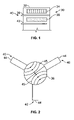
- FIG. 1 is a diagram of an exemplary embodiment of a ferrite circulator.
- FIG. 2 is a diagram illustrating electric field configurations controlling the operation of a ferrite circulator.
- FIG. 3 is a top plan view of a ferrite circulator housing constructed in accordance with an exemplary embodiment of the invention.
- FIG. 4 is a section view of the ferrite circulator housing of FIG. 3 taken along the line 4 — 4 .
- FIG. 5 is an exploded perspective view of a ferrite circulator in accordance with an exemplary embodiment of the invention.
- FIG. 6 is a section view of a ferrite circulator in accordance with an exemplary embodiment of the invention.
- FIG. 1 illustrates an exemplary embodiment of a ferrite circulator 30 in accordance with an exemplary embodiment.
- the ferrite circulator 30 generally includes a housing 32 defined by a body having a one or more magnets 34 and one or more ferrite elements 36 (e.g., ferrite slab or disk) aligned therein.
- the housing 32 is constructed of a metal, such as, for example, steel or aluminum, and which in one embodiment forms a cylindrical cavity resonator.
- the ferrite circulator 30 also includes a plurality of stripline circuits 38 (only one of the stripline circuits 38 is shown in FIG. 1 ) defining ports 40 of the ferrite circulator 30 .
- a Y junction ferrite circulator 30 may be formed by providing three stripline circuits 38 defining three different ports 40 .
- the ferrite circulator 30 also may include a ground plane 42 for establishing a ground reference within the ferrite circulator 30 . It should be noted that a dielectric (not shown) between different components, for example, between the ground plane 42 and stripline circuit 38 may be provided within the housing 32 of the ferrite circulator 30 .
- additional magnets 34 and ferrite elements 36 may be provided in a stacked arrangement within the housing 32 .
- additional stripline circuits 38 defining additional ports 40 may be provided (e.g., four stripline circuits defining a four-port ferrite circulator 30 ).
- power may be applied to any one of a plurality of transmission lines 44 defined by ports 40 that are formed by stripline circuits 38 extending outside the housing 32 .
- a standing wave pattern 45 is established. This electromagnetic field pattern is caused by counter-rotating waves created within the housing 32 . It should be noted that coupling and isolation within the ferrite circulator 30 are determined by the relative position of a port 40 and the standing wave pattern.
- the presence of an induced axial magnetic field across the ferrite element 36 changes the effective permeability experienced by the rotating waves based upon the sense of rotation. This causes rotation of the standing wave patterns.
- the ferrite circulator 30 may be configured such that the power transfer and isolation properties are provided such that the standing wave pattern is rotated thirty degrees.
- one of the ports 40 may be internally terminated to provide a two-port isolator.
- a plurality of alignment members 50 integrally formed as part of the housing 32 to align a ferrite element 36 therein are provided as described in more detail herein.
- the plurality of alignment members 50 extend generally perpendicularly to a plane of a bottom surface 52 of the housing 32 , for example, as protrusions, to define an alignment region 54 for maintaining therein a ferrite element 36 .
- the alignment region 54 is provided as a generally planar area for supporting the ferrite element 36 substantially horizontally relative to sides 56 (e.g., walls) of the housing 32 and between the alignment members 50 .
- the number and configuration of the alignment members 50 may be modified as desired or needed.
- the alignment members 50 are shown as generally cylindrical posts, the shape of the alignment members 50 may be provided having, for example, a square, rectangular, octagonal or other geometric shaped cross-section.
- the height of the alignment members 50 may be modified to accommodate (e.g., receive in the alignment region 54 ) and maintain therein more than one ferrite element 36 provided in a stacked arrangement.
- the number and positioning of the alignment members 50 may be modified to accommodate different sizes and shapes of ferrite elements 36 .
- the alignment members 50 may be arranged to define a square, rectangular, octagonal or other geometrically shaped alignment region 54 for receiving and maintaining therein or therebetween a correspondingly shaped ferrite element 36 .
- the alignment region 54 defined by the plurality of alignment members 50 is sized smaller than the magnet 34 (shown in FIG. 1 ).
- the alignment region 54 may have a diameter approximately twenty percent smaller than the diameter of the magnet 34 .
- the height of the alignment members 50 may be about equal to the thickness of the one or more ferrite elements 36 or may be sized slightly higher than the one or more ferrite elements 36 (e.g., five percent higher).
- the alignment members 50 are integrally formed as part of the housing 32 in the various embodiments.
- the alignment members 50 may be formed into the housing 32 using a machining, stamping, casting and/or molding process, which may be a single or multiple step process.
- a two step process is performed to form the alignment members 50 and alignment region 54 .
- the alignment members 50 are formed (e.g., by stamping or pulling up posts from the bottom surface 52 ) and in a second step, the planar alignment region 54 is formed.
- this two step process may include, for example, a first machining strike to form the alignment members 50 (e.g., posts) and a second machining strike to flatten the alignment region 54 to provide a planar surface.
- the alignment members 50 may be formed at any position along the bottom surface 52 of the housing 32 .
- the alignment members 50 are centered in the housing 32 relative to the sides 56 (e.g., walls) of the housing 32 .
- the number and positioning of the alignment members 50 may be provided at any location along the bottom surface 52 of the housing 32 .
- the integral forming of the alignment members 50 as part of the housing 32 to form a single unitary piece may be provided by any suitable process, including, but not limited to, shearing, extruding, punching, etc.
- the alignment members 50 may be formed in the housing 32 at the time of molding or casting, or as part of a secondary step.
- a ferrite circulator 30 having a housing 32 with integrally formed alignment members 50 is provided.
- a dimpled housing 32 or a housing 32 having posts formed thereon may be provided.
- the housing 32 is constructed having a plurality of openings 60 formed in the sides 56 to allow extension therefrom of stripline circuits 38 to define ports 40 of the ferrite circulator 30 .
- one or more ferrite elements 36 are inserted within the alignment region 54 defined by the plurality of alignment members 50 .
- a circuit element 62 comprising a plurality of stripline circuits 38 is provided on top of the ferrite element 36 .
- a spacer 64 which may be formed of a dielectric material is then provided between the circuit element 62 and a magnet 34 .
- a pole piece 66 is provided on top of the magnet 34 and a cover return 68 is provided on top of the pole piece 66 .
- a cover 70 is then provided on top of the cover return 68 .
- the spacer 64 is provided between the circuit element 62 and the magnet 34 to minimize the “lossyness” of the circuit element 62 that would occur if the magnet 34 contacts the circuit element 62 .
- the pole piece 66 and return cover 68 are provided and configured to focus the magnetic fields within the housing 32 as is known and to direct flow of energy therethrough.
- the cover 70 is spring loaded to apply a downward force on the components within the housing 32 to maintain the position and alignment of the components therein.
- the cover 70 and housing 32 may have complimenting locking or latching portion to secure the cover 70 to the housing 32 (e.g., snap fit).
- a ferrite circulator 30 is constructed having a stacked arrangement of components therein with the ferrite element 36 maintained in alignment with the other components using the plurality of alignment members 50 .
- the various components may be secured to one another, for example, by glue, epoxy or other suitable material. Additionally, the components may be maintained in position relative to each other by a force supplied by the cover 70 .
- the number and configuration of each component e.g., the number and shape of ferrite elements 36
- the alignment region 54 for maintaining the position of the ferrite element 36 is generally smaller in diameter than the other components of the ferrite circulator 30 such that a gap 72 is provided between the plurality of alignment members 50 and the sides 56 of the housing 32 .
- the plurality of alignment members 50 are spaced a distance from the sides 56 of the housing 32 .
- the other components of the ferrite circulator 30 are configured in a stacked arrangement on top of the ferrite element 36 as is known.
Abstract
Description
Claims (19)
Priority Applications (4)
| Application Number | Priority Date | Filing Date | Title |
|---|---|---|---|
| US10/894,812 US7170362B2 (en) | 2004-07-20 | 2004-07-20 | Ferrite circulator having alignment members |
| JP2005209864A JP2006033866A (en) | 2004-07-20 | 2005-07-20 | Ferrite circulator having positioning member |
| EP05106625A EP1619744A1 (en) | 2004-07-20 | 2005-07-20 | Ferrite circulator having alignment members |
| CN200510092285.7A CN1744376A (en) | 2004-07-20 | 2005-07-20 | Ferrite circulator having alignment members |
Applications Claiming Priority (1)
| Application Number | Priority Date | Filing Date | Title |
|---|---|---|---|
| US10/894,812 US7170362B2 (en) | 2004-07-20 | 2004-07-20 | Ferrite circulator having alignment members |
Publications (2)
| Publication Number | Publication Date |
|---|---|
| US20060017520A1 US20060017520A1 (en) | 2006-01-26 |
| US7170362B2 true US7170362B2 (en) | 2007-01-30 |
Family
ID=35064656
Family Applications (1)
| Application Number | Title | Priority Date | Filing Date |
|---|---|---|---|
| US10/894,812 Active 2024-07-21 US7170362B2 (en) | 2004-07-20 | 2004-07-20 | Ferrite circulator having alignment members |
Country Status (4)
| Country | Link |
|---|---|
| US (1) | US7170362B2 (en) |
| EP (1) | EP1619744A1 (en) |
| JP (1) | JP2006033866A (en) |
| CN (1) | CN1744376A (en) |
Cited By (2)
| Publication number | Priority date | Publication date | Assignee | Title |
|---|---|---|---|---|
| US20100102896A1 (en) * | 2008-10-28 | 2010-04-29 | Hitachi Global Storage Technologies Nethetrlands B.V. | Microwave circulator with thin-film exchange-coupled magnetic structure |
| US9000859B2 (en) | 2013-03-19 | 2015-04-07 | Honeywell International Inc. | Ferrite circulator with asymmetric dielectric spacers |
Families Citing this family (8)
| Publication number | Priority date | Publication date | Assignee | Title |
|---|---|---|---|---|
| JP4817050B2 (en) * | 2006-02-07 | 2011-11-16 | 日立金属株式会社 | Non-reciprocal circuit element |
| JP4811578B2 (en) * | 2006-03-31 | 2011-11-09 | Tdk株式会社 | Non-reciprocal circuit device and communication device |
| KR101279487B1 (en) | 2012-05-18 | 2013-06-27 | 쓰리알웨이브 (주) | Non-reciprocal circuit device with single ferrite unit |
| KR101378741B1 (en) * | 2013-09-04 | 2014-03-27 | 쓰리알웨이브 (주) | Non-reciprocal circuit element capable of magnetostatic field |
| KR101378740B1 (en) * | 2013-10-10 | 2014-03-27 | 쓰리알웨이브 (주) | Non reciprocal circuit device of distributed circuit type combined with lumped circuit element |
| US10333192B2 (en) | 2016-05-20 | 2019-06-25 | Smiths Interconnect, Inc. | Below resonance circulator and method of manufacturing the same |
| CN107887710B (en) * | 2017-03-29 | 2019-03-29 | 比亚迪股份有限公司 | Antenna, requestor antenna, transponder antenna and answering system |
| WO2019118870A1 (en) * | 2017-12-14 | 2019-06-20 | Trak Microwave Corporation | Broadband circulator and method of manufacturing the same |
Citations (11)
| Publication number | Priority date | Publication date | Assignee | Title |
|---|---|---|---|---|
| US3621476A (en) * | 1969-10-02 | 1971-11-16 | Tdk Electronics Co Ltd | Circulator having heat dissipating plate |
| US4145672A (en) | 1976-11-12 | 1979-03-20 | Trw Inc. | Microwave ferrite circulator having dielectric tube for housing circulator elements |
| EP0005801A1 (en) | 1978-05-25 | 1979-12-12 | Hitachi Metals, Ltd. | Microwave ferrite component |
| US4276522A (en) * | 1979-12-17 | 1981-06-30 | General Dynamics | Circulator in a stripline microwave transmission line circuit |
| US4791389A (en) | 1987-05-27 | 1988-12-13 | Varian Associates, Inc. | Millimeter wave circulator |
| US5384556A (en) | 1993-09-30 | 1995-01-24 | Raytheon Company | Microwave circulator apparatus and method |
| US5638033A (en) | 1995-12-27 | 1997-06-10 | Hughes Electronics | Three port slot line circulator |
| US6011449A (en) | 1997-02-18 | 2000-01-04 | The Whitaker Corporation | Surface mount technology contact for ferrite isolator/circulator applications |
| US6337607B1 (en) | 2000-05-12 | 2002-01-08 | Renaissance Electronics Corporation | Surface mountable low IMD ferrite isolator/circulator structure |
| US6504445B1 (en) | 2001-12-07 | 2003-01-07 | Renaissance Electronics Corporation | Surface mountable low IMD circulator/isolator with a locking cover and assembly method |
| US6566972B2 (en) | 2001-06-14 | 2003-05-20 | Tyco Electronics Corporation | Ferrite-circuit aligning frame |
Family Cites Families (3)
| Publication number | Priority date | Publication date | Assignee | Title |
|---|---|---|---|---|
| JPH0445281Y2 (en) * | 1985-08-28 | 1992-10-26 | ||
| JPH0379506U (en) * | 1989-12-04 | 1991-08-14 | ||
| JP3570023B2 (en) * | 1995-07-25 | 2004-09-29 | 株式会社村田製作所 | Non-reciprocal circuit device |
-
2004
- 2004-07-20 US US10/894,812 patent/US7170362B2/en active Active
-
2005
- 2005-07-20 EP EP05106625A patent/EP1619744A1/en not_active Ceased
- 2005-07-20 JP JP2005209864A patent/JP2006033866A/en active Pending
- 2005-07-20 CN CN200510092285.7A patent/CN1744376A/en active Pending
Patent Citations (13)
| Publication number | Priority date | Publication date | Assignee | Title |
|---|---|---|---|---|
| US3621476A (en) * | 1969-10-02 | 1971-11-16 | Tdk Electronics Co Ltd | Circulator having heat dissipating plate |
| US4145672A (en) | 1976-11-12 | 1979-03-20 | Trw Inc. | Microwave ferrite circulator having dielectric tube for housing circulator elements |
| EP0005801A1 (en) | 1978-05-25 | 1979-12-12 | Hitachi Metals, Ltd. | Microwave ferrite component |
| US4276522A (en) * | 1979-12-17 | 1981-06-30 | General Dynamics | Circulator in a stripline microwave transmission line circuit |
| US4791389A (en) | 1987-05-27 | 1988-12-13 | Varian Associates, Inc. | Millimeter wave circulator |
| US5384556A (en) | 1993-09-30 | 1995-01-24 | Raytheon Company | Microwave circulator apparatus and method |
| US5638033A (en) | 1995-12-27 | 1997-06-10 | Hughes Electronics | Three port slot line circulator |
| US6011449A (en) | 1997-02-18 | 2000-01-04 | The Whitaker Corporation | Surface mount technology contact for ferrite isolator/circulator applications |
| US6337607B1 (en) | 2000-05-12 | 2002-01-08 | Renaissance Electronics Corporation | Surface mountable low IMD ferrite isolator/circulator structure |
| US6566972B2 (en) | 2001-06-14 | 2003-05-20 | Tyco Electronics Corporation | Ferrite-circuit aligning frame |
| US6504445B1 (en) | 2001-12-07 | 2003-01-07 | Renaissance Electronics Corporation | Surface mountable low IMD circulator/isolator with a locking cover and assembly method |
| US20030107448A1 (en) | 2001-12-07 | 2003-06-12 | Kocharyan Karen N. | Surface mountable circulator/isolator and assembly technique |
| US6850126B2 (en) * | 2001-12-07 | 2005-02-01 | Renaissance Electronics Corporation | Surface mountable circulator/isolator and assembly technique |
Cited By (5)
| Publication number | Priority date | Publication date | Assignee | Title |
|---|---|---|---|---|
| US20100102896A1 (en) * | 2008-10-28 | 2010-04-29 | Hitachi Global Storage Technologies Nethetrlands B.V. | Microwave circulator with thin-film exchange-coupled magnetic structure |
| US7816994B2 (en) | 2008-10-28 | 2010-10-19 | Hitachi Global Storage Technologies Netherlands B.V. | Microwave circulator with thin-film exchange-coupled magnetic structure |
| US9000859B2 (en) | 2013-03-19 | 2015-04-07 | Honeywell International Inc. | Ferrite circulator with asymmetric dielectric spacers |
| US9184480B2 (en) | 2013-03-19 | 2015-11-10 | Honeywell International Inc. | Ferrite circulator with asymmetric dielectric spacers |
| US9531050B2 (en) | 2013-03-19 | 2016-12-27 | Honeywell International Inc. | Ferrite circulator with asymmetric dielectric spacers |
Also Published As
| Publication number | Publication date |
|---|---|
| CN1744376A (en) | 2006-03-08 |
| JP2006033866A (en) | 2006-02-02 |
| US20060017520A1 (en) | 2006-01-26 |
| EP1619744A1 (en) | 2006-01-25 |
Similar Documents
| Publication | Publication Date | Title |
|---|---|---|
| EP1619744A1 (en) | Ferrite circulator having alignment members | |
| US9859602B2 (en) | Non-reciprocal circuit device and communication apparatus using the same | |
| KR102050567B1 (en) | Compact Non-reciprocal Circuit Element | |
| US7385454B2 (en) | Ferrite housing for microwave devices | |
| US5384556A (en) | Microwave circulator apparatus and method | |
| US9735458B2 (en) | Non-reciprocal circuit device and communication apparatus using the same | |
| US6822524B2 (en) | Compact multi-element cascade circulator | |
| US7659792B2 (en) | Circulator device and a method for assembly | |
| EP3459139B1 (en) | Below resonance circulator and method of manufacturing the same | |
| US7936231B2 (en) | Circulator/isolator housing with inserts | |
| USH1408H (en) | Microwave circulator with a planar, biasing, permanent magnet | |
| JP4151009B2 (en) | Non-reciprocal circuit element | |
| CN103928734B (en) | A kind of processing technique of circulator and isolator shell | |
| JP2005184676A (en) | Irreversible circuit element | |
| JP2570669B2 (en) | Non-reciprocal circuit device | |
| JP2006033055A (en) | Method for regulating non-reciprocal circuit element | |
| JPH04277902A (en) | Distribution parameter type circulator and isolator | |
| US6590484B2 (en) | Insulated circulator | |
| JP2023067826A (en) | Non-reciprocal circuit element and communication device having the same | |
| US20060158047A1 (en) | Non-reciprocal circuit device | |
| JP2003115702A (en) | Nonreciprocal circuit element and communication apparatus thereof | |
| JP2606381Y2 (en) | Stripline type non-reciprocal circuit device | |
| JPH0729727A (en) | Non-reciprocal circuit element | |
| JPH0823212A (en) | Irreversible circuit element | |
| JP2006157089A (en) | Nonreciprocal circuit element |
Legal Events
| Date | Code | Title | Description |
|---|---|---|---|
| AS | Assignment |
Owner name: M/A COM, INC., MASSACHUSETTS Free format text: ASSIGNMENT OF ASSIGNORS INTEREST;ASSIGNORS:KINGSTON, JAMES PAUL;PAQUETTE, STANLEY VINCENT;REEL/FRAME:015630/0637 Effective date: 20040714 |
|
| STCF | Information on status: patent grant |
Free format text: PATENTED CASE |
|
| AS | Assignment |
Owner name: COBHAM DEFENSE ELECTRONIC SYSTEMS CORPORATION, MAS Free format text: ASSIGNMENT OF ASSIGNORS INTEREST;ASSIGNORS:M/A COM, INC.;RAYCHEM INTERNATIONAL;TYCO ELECTRONICS CORPORATION;AND OTHERS;REEL/FRAME:022266/0400;SIGNING DATES FROM 20080108 TO 20090113 Owner name: COBHAM DEFENSE ELECTRONIC SYSTEMS CORPORATION,MASS Free format text: ASSIGNMENT OF ASSIGNORS INTEREST;ASSIGNORS:M/A COM, INC.;RAYCHEM INTERNATIONAL;TYCO ELECTRONICS CORPORATION;AND OTHERS;SIGNING DATES FROM 20080108 TO 20090113;REEL/FRAME:022266/0400 Owner name: COBHAM DEFENSE ELECTRONIC SYSTEMS CORPORATION, MAS Free format text: ASSIGNMENT OF ASSIGNORS INTEREST;ASSIGNORS:M/A COM, INC.;RAYCHEM INTERNATIONAL;TYCO ELECTRONICS CORPORATION;AND OTHERS;SIGNING DATES FROM 20080108 TO 20090113;REEL/FRAME:022266/0400 |
|
| AS | Assignment |
Owner name: COBHAM DEFENSE ELECTRONIC SYSTEMS CORPORATION, MAS Free format text: SECURITY AGREEMENT;ASSIGNOR:KIWI STONE ACQUISITION CORP.;REEL/FRAME:022482/0016 Effective date: 20090330 Owner name: COBHAM DEFENSE ELECTRONIC SYSTEMS CORPORATION,MASS Free format text: SECURITY AGREEMENT;ASSIGNOR:KIWI STONE ACQUISITION CORP.;REEL/FRAME:022482/0016 Effective date: 20090330 |
|
| AS | Assignment |
Owner name: KIWI STONE ACQUISITION CORPORATION, CALIFORNIA Free format text: ASSIGNMENT OF ASSIGNORS INTEREST;ASSIGNOR:COBHAM DEFENSE ELECTRONIC SYSTEMS CORPORATION;REEL/FRAME:022714/0890 Effective date: 20090521 Owner name: KIWI STONE ACQUISITION CORPORATION,CALIFORNIA Free format text: ASSIGNMENT OF ASSIGNORS INTEREST;ASSIGNOR:COBHAM DEFENSE ELECTRONIC SYSTEMS CORPORATION;REEL/FRAME:022714/0890 Effective date: 20090521 |
|
| AS | Assignment |
Owner name: M/A-COM TECHNOLOGY SOLUTIONS HOLDINGS, INC., MASSA Free format text: CHANGE OF NAME;ASSIGNOR:KIWI STONE ACQUISITION CORP.;REEL/FRAME:023476/0069 Effective date: 20090526 Owner name: M/A-COM TECHNOLOGY SOLUTIONS HOLDINGS, INC.,MASSAC Free format text: CHANGE OF NAME;ASSIGNOR:KIWI STONE ACQUISITION CORP.;REEL/FRAME:023476/0069 Effective date: 20090526 |
|
| FPAY | Fee payment |
Year of fee payment: 4 |
|
| AS | Assignment |
Owner name: RBS BUSINESS CAPITAL, A DIVISION OF RBS ASSET FINA Free format text: SECURITY AGREEMENT;ASSIGNORS:MIMIX BROADBAND, INC.;M/A-COM TECHNOLOGY SOLUTIONS HOLDINGS, INC.;REEL/FRAME:025444/0920 Effective date: 20101203 |
|
| AS | Assignment |
Owner name: M/A-COM TECHNOLOGY SOLUTIONS HOLDINGS, INC., MASSA Free format text: RELEASE BY SECURED PARTY;ASSIGNOR:COBHAM DEFENSE ELECTRONIC SYSTEMS CORPORATION;REEL/FRAME:025445/0947 Effective date: 20101203 |
|
| AS | Assignment |
Owner name: MIMIX BROADBAND, INC., MASSACHUSETTS Free format text: RELEASE OF SECURITY INTEREST RECORDED AT REEL/FRAME 25444/920;ASSIGNOR:RBS BUSINESS CAPITAL, A DIVISION OF RBS ASSET FINANCE, INC., AS ADMINISTRATIVE AGENT;REEL/FRAME:027028/0021 Effective date: 20110930 Owner name: M/A-COM TECHNOLOGY SOLUTIONS HOLDINGS, INC., MASSA Free format text: RELEASE OF SECURITY INTEREST RECORDED AT REEL/FRAME 25444/920;ASSIGNOR:RBS BUSINESS CAPITAL, A DIVISION OF RBS ASSET FINANCE, INC., AS ADMINISTRATIVE AGENT;REEL/FRAME:027028/0021 Effective date: 20110930 |
|
| FPAY | Fee payment |
Year of fee payment: 8 |
|
| AS | Assignment |
Owner name: SKYWORKS SOLUTIONS, INC., MASSACHUSETTS Free format text: ASSIGNMENT OF ASSIGNORS INTEREST;ASSIGNOR:SKYWORKS IRELAND LIMITED;REEL/FRAME:037832/0842 Effective date: 20151028 |
|
| MAFP | Maintenance fee payment |
Free format text: PAYMENT OF MAINTENANCE FEE, 12TH YEAR, LARGE ENTITY (ORIGINAL EVENT CODE: M1553) Year of fee payment: 12 |
|
| AS | Assignment |
Owner name: TRANS-TECH, INC., MARYLAND Free format text: ASSIGNMENT OF ASSIGNORS INTEREST;ASSIGNOR:SKYWORKS SOLUTIONS, INC.;REEL/FRAME:063727/0270 Effective date: 20230407 |
|
| AS | Assignment |
Owner name: ALLUMAX TTI, LLC, MICHIGAN Free format text: ASSIGNMENT OF ASSIGNORS INTEREST;ASSIGNOR:TRANS-TECH, INC.;REEL/FRAME:063991/0097 Effective date: 20230407 |