US5373970A - Liquid soap dispenser for simplified replacement of soap reservoir - Google Patents
Liquid soap dispenser for simplified replacement of soap reservoir Download PDFInfo
- Publication number
- US5373970A US5373970A US08/172,390 US17239093A US5373970A US 5373970 A US5373970 A US 5373970A US 17239093 A US17239093 A US 17239093A US 5373970 A US5373970 A US 5373970A
- Authority
- US
- United States
- Prior art keywords
- orientation
- engagement means
- reservoir
- engagement
- dispenser
- Prior art date
- Legal status (The legal status is an assumption and is not a legal conclusion. Google has not performed a legal analysis and makes no representation as to the accuracy of the status listed.)
- Expired - Lifetime
Links
Images


Classifications
-
- A—HUMAN NECESSITIES
- A47—FURNITURE; DOMESTIC ARTICLES OR APPLIANCES; COFFEE MILLS; SPICE MILLS; SUCTION CLEANERS IN GENERAL
- A47K—SANITARY EQUIPMENT NOT OTHERWISE PROVIDED FOR; TOILET ACCESSORIES
- A47K5/00—Holders or dispensers for soap, toothpaste, or the like
- A47K5/06—Dispensers for soap
- A47K5/12—Dispensers for soap for liquid or pasty soap
- A47K5/1202—Dispensers for soap for liquid or pasty soap dispensing dosed volume
- A47K5/1204—Dispensers for soap for liquid or pasty soap dispensing dosed volume by means of a rigid dispensing chamber and pistons
- A47K5/1207—Dispensing from the bottom of the dispenser with a vertical piston
Definitions
- This invention relates generally to fluid dispensers, and more particularly to a liquid soap dispenser which is adapted for simplified replacement of a liquid soap reservoir.
- liquid hand soap Many of todays products sold in liquid form, such as liquid hand soap, are contained in disposable containers or reservoirs which incorporate a pump assembly.
- the pump assembly includes a reciprocally movable element, which when moved dispenses a quantity of liquid soap from the reservoir.
- the reservoirs are fitted within a permanent housing which includes a movable actuator assembly which secures and reciprocally moves the movable element to dispense the fluid.
- This has been found to be both a convenient and economical means of fluid supply and dispensation. As the fluid reservoirs are replaced once the fluid supply is exhausted, it is desirable to manufacture the dispenser and reservoir so as to make replacement of the fluid reservoir as easy and quick as possible.
- Known fluid dispensers suffer the disadvantage in that replacement of the fluid reservoir is time consuming, as care must be taken to ensure the reservoir is placed in the permanent housing in the correct dispensing position to dispense fluids. If the reservoir is not placed in the correct dispensing position with the movable element coupled to the actuator assembly, the dispenser will be inoperative as the movement of the actuator assembly will not reciprocally move the movable element and no fluids will be dispensed. To achieve the proper dispensing configuration, the pump assembly must therefore be precisely aligned in the housing to ensure it is properly secured in or coupled to the actuator assembly.
- the present invention provides a fluid dispenser comprising a housing and a replaceable fluid reservoir, wherein on initial use or cycling of the dispenser, the housing and the fluid reservoir assume an orientation where the reservoir is secured or coupled to the housing in a proper configuration to dispense fluids.
- An object of the present invention is to provide an improved fluid dispenser having a housing and a replaceable reservoir which incorporates as part of a fluid dispensing valve, a movable element.
- the housing includes a movable actuator assembly for coupling to the movable element. When the actuator assembly and movable element are coupled, the movement of the actuator assembly moves the movable element to dispense fluid from the reservoir.
- the actuator assembly is configured such that if the reservoir is inserted into the housing in a position uncoupled from the actuator assembly, the first activation of the dispenser moves the actuator assembly relative to the movable element to a position where the movable element and actuator assembly are secured together in a coupled orientation.
- Another object of the invention is to provide a dispenser which will permit insertion of a replaceable reservoir therein regardless of the initial position of the movable element.
- a further object is to provide an improved dispenser for the dispensation of liquid soap.
- the present invention provides a fluid dispenser which includes a replaceable reservoir and a permanent housing.
- the housing is configured to support the reservoir in a dispensing position.
- the reservoir includes a chamber for holding fluids and a portioning valve which includes a reciprocally movable element, the movement of which dispenses predetermined amount of fluid outwardly from the chamber.
- the housing includes an actuator assembly movable between first and second positions. The actuator assembly is adapted for coupling to the reciprocally movable element, wherein in a coupled orientation the movement of the actuator assembly moves the movable element to dispense fluid.
- the actuator assembly is further configured such that if the reservoir is inserted into the housing with the reciprocally movable element uncoupled, so that the movable element and actuator assembly may move independently, on first cycling of the actuator assembly, the actuator assembly is moved relative to the reciprocally movable element to secure it thereto.
- cycling of the actuator assembly it is generally meant the movement of the actuator assembly from the first position to the second position and back to the first position during the normal operation of the dispenser.
- the dispenser of the present invention advantageously permits quicker replacement of the reservoir, as it is not required to precisely align the reciprocally movable element with the actuator assembly to ensure the reservoir is inserted into the housing with the movable element and actuator assembly in a coupled orientation. Additionally, as there is no longer the need to adjust the position of the reciprocally movable element on the insertion of the reservoir, the disadvantages of inoperative arrangement and/or premature dispensation or escape of fluids from the chamber are eliminated.
- one of the actuator assembly and the reciprocally movable element includes a catch assembly.
- the catch assembly is configured to permit movement of the actuator assembly relative to the reciprocally movable element from a position where the actuator assembly and reciprocally movable element are in an uncoupled orientation, to a position where the actuator assembly and reciprocally movable element are in a coupled orientation. Once in the coupled orientation, the catch assembly prevents movement of the actuator assembly relative to the movable element to return to the uncoupled orientation.
- the reciprocally movable member is a piston which, on insertion of the reservoir into the housing, is substantially positioned in a cavity formed in the actuator assembly.
- the piston includes an engagement flange, which on insertion of the reservoir, either locates fully within a first zone of the cavity, wherein the piston and actuator assembly are in the coupled orientation, or the engagement flange locates at least partially in a zone of the cavity other than the first zone, wherein the piston and actuator assembly are in the uncoupled orientation.
- the first cycling of the actuator assembly moves the actuator assembly relative to the piston until the engagement flange is positioned fully within the first zone.
- the catch assembly preferably forms part of the actuator assembly and includes one or more fingers. Each finger carries at a first end a tab. The first end of the fingers are resiliently deformable from an unbiased position to a biased position. In the unbiased position, the tabs are positioned to engage and retain the engagement flange of the piston when it is fully in the first zone, substantially preventing its withdrawal therefrom. In the biased position, the tabs are moved out of contact with the piston sufficiently to permit movement of the actuator assembly relative to the piston.
- the fingers When the engagement flange is positioned fully in the first zone, the fingers assume the unbiased position, with the tabs engaging the engagement flange to couple it to the catch assembly.
- the first cycling of the actuator assembly moves the fingers to the biased position and the catch assembly is moved relative to the piston so that the engagement flange is relocated fully in the first zone.
- the resiliency of the fingers causes their return to the unbiased position, coupling the piston to the actuator assembly.
- the cavity in which the engagement flange locates comprises a slot having a lateral dimension defined by two or more of the fingers.
- the reservoir is inserted into the housing by sliding the piston radially inward into the slot in a direction transverse to the direction of axial movement of the catch assembly.
- the piston is positioned between the fingers, axially aligned in the slot. The movement of the actuator assembly causes the axial reciprocal movement of the catch assembly together with the piston to dispense fluid.
- each tab projects angularly from its associated finger such that a leading surface of each tab forms a camming surface.
- the first cycling of the dispenser moves the leading surfaces into contact with the piston to assist in moving the fingers to the biased position.
- a trailing edge or surface of the tabs engages the engagement flange to couple the piston to the actuator assembly.
- a leading surface it is generally meant, the surface of the tab which forms an obtuse angle with the remainder of the finger.
- a trailing edge or surface it is generally meant the surface of the tab opposite the leading surface or the edge portion of the tab therebetween.
- a dispenser for dispensing fluid comprising, a housing, a reservoir, the housing supporting the reservoir in a dispensing position, the reservoir being insertable into said housing to assume said dispensing position and removable therefrom for replacement, the reservoir comprising, (i) a chamber for retaining fluid having an outlet, and (ii) valve means disposed across the outlet for dispensing fluid from the chamber, the valve means comprising a reciprocally movable element for reciprocal movement relative to the housing when the reservoir is in the dispensing position to dispense fluid, the reciprocally movable element including engagement means, the housing including actuator means movable relative the housing between a first position and a second position, the actuator means including catch means, the actuator means further having a cavity to receive the engagement means therein when the reservoir is in the dispensing position, the cavity having a first zone and a second zone, wherein on insertion of the reservoir into the housing into the dispensing position, the engagement means is located in the cavity disposed in one of:
- a dispenser for dispensing fluid comprising, a housing, a reservoir, the housing supporting the reservoir in a dispensing position, the reservoir being insertable into said housing to assume said dispensing position and removable therefrom for replacement, the reservoir comprising, (i) a chamber for retaining fluid having an outlet, and (ii) valve means disposed across the outlet for dispensing fluid from the chamber, the valve means comprising a reciprocally movable element for reciprocal movement relative to the housing when the reservoir is in the dispensing position to dispense fluid, the reciprocally movable element including engagement means, the housing including actuator means movable relative a remainder of the housing between a first position and a second position, the actuator means including catch means to engage the engagement means a couple the reciprocally movable element to the actuator means, wherein when the reservoir is inserted into the dispensing position, the engagement means and catch means assume relative positions selected from; (a) a coupled orientation in which the catch means engages the engagement means for reciprocal movement of the element to
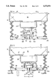
- FIG. 1 is an exploded partial perspective view of a preferred embodiment of a housing and reservoir in accordance with the invention with the housing open for reservoir insertion;
- FIG. 2 is a partial cross sectional view of the preferred embodiment of the housing and reservoir of FIG. 1 in a coupled first orientation with the actuator assembly and the reciprocally movable piston element in a first fully extended rest position;
- FIG. 3 is a partial perspective view of the reservoir and housing of FIG. 1 in a coupled first orientation with the activator assembly and piston element moved to a second fully retracted position;
- FIGS. 4 and 5 show partial perspective views of the identical housing and reservoir of FIG. 2 with the actuator assembly and piston element in uncoupled second and third orientations;
- FIG. 6 is an exploded partial perspective of a housing and reservoir in accordance with a second embodiment of the invention with the housing closed for dispensing fluid;
- FIG. 7 is a partial cross sectional view of the piston engagement flange and the catch assembly taken along line 7--7' of FIG. 6.
- FIG. 1 shows a dispenser 10 in accordance with a preferred embodiment of the invention.
- the dispenser 10 comprises a reservoir 12, and a housing 14.
- the reservoir 12 comprises a chamber 16 for holding fluid 18, as for example liquid soap, which is to be dispensed.
- An outlet 20 is provided through a lower most wall 17 of the chamber 16, across which is located a valve assembly 22 to regulate the flow of fluid 18 outwardly therethrough.
- the reservoir 12 is made entirely of plastic and is disposable once the supply of fluid 18 is exhausted.
- FIG. 1 shows the housing 14 in an open configuration, ready for insertion of the reservoir 12.
- the housing 14 includes a cover 24 which is hingely connected to a backplate 26 adapted for permanent attachment to a wall by screws 8 or other known means.
- the cover 24 pivots relative to the back plate 26 about hinge pivot 25 in a known manner from the open position, which permits removal and replacement of the reservoir 12, in the direction of arrow 4 to a closed position, wherein the dispenser may be used to dispense fluid 18.
- the cover 24 open to the piston shown in FIG. 1 the reservoir 12 is inserted into the housing 14 with the outlet 20 oriented upwardly.
- the movement of the cover 24 to the closed position inverts the reservoir 12 so that the outlet 20 is reoriented downwards ready to dispense fluid 18.
- the cover 24 is formed having a generally box-like shape so as to define a reservoir cavity 28 in which the reservoir 12 is housed. With the reservoir 12 inserted in the cavity 28, the cover 24 is closed to move the reservoir 12 to a dispensing position wherein the fluid 18 may be dispensed outwardly via the opening 20 and valve assembly 22.
- An actuator assembly 30 is provided in the housing 14, movable relative to the cover 24 to activate a movable piston element 78 of the valve assembly 22, and effect fluid 18 dispensation.
- the present invention is focused on the actuator assembly 30, which includes generally a lever 32 which is pivotally connected to the cover 24, and a catch assembly 34 for engaging and securing part of the piston element 78 thereto.
- the lever 32 includes, and pivots in the direction of arrow 6 about the axis of, a metal rod 33 which extends across the cover 24.
- One end of the lever 32 abuttingly contacts the catch assembly 34 such that pivotal movement of the lever 32 moves the catch assembly 34 between a first rest position spaced from the reservoir 12, and a second fully inserted position wherein the catch assembly 34 is moved thereto.
- the actuator assembly 30 permits the sliding insertion of the reciprocally movable piston element 78 into the catch assembly 34 either into an orientation where the catch assembly 34 and piston element 78 are coupled for movement together, as shown in FIG. 2, or an uncoupled orientation where the catch assembly 34 may move independently from the piston element 78, shown in FIGS. 4 and 5.
- the pivotal movement of the lever 32 axially moves the catch assembly 34 and piston element 78 between the first rest and second fully retracted positions, to dispense a quantity of fluid 18.
- the first movement of the lever 32 moves the catch assembly 34 relative to the piston element 78 until the catch assembly 34 engages the piston element 78 and assumes the coupled orientation of FIG. 2.
- the dispenser 10 is operative to dispense fluid 18 regardless of whether the piston element 78 is initially inserted into the housing 14 either coupled or uncoupled to the catch assembly 34.
- the catch assembly 34 includes a shoulder member 36 having a tabular surface 38 which is oriented uppermost towards the chamber 16 when the reservoir 12 is inserted and the cover 24 is closed.
- a pair of substantially parallel spaced metal fingers 40,42 extend from the tabular surface 38 towards the chamber 16, the fingers 40,42 substantially defining the lateral extent of a cavity or slot 43 therebetween.
- Each finger 40,42 comprises a flattened ribbon of metal, formed so that a first endmost portion 44,46 of each respective finger 40,42 which is remote from the shoulder member 36 is resiliently deformable from an unbiased position, wherein the fingers 40,42 assume their substantially parallel configuration, to a biased position, wherein the endmost portions 44,46 are moved apart.
- finger endmost portion 44 includes an integrally formed projecting tab 48, with finger endmost portion 46 including integrally formed projecting tab 50.
- the tabs 48,50 are generally located along each respective finger 40,42, an equal distance from the tabular surface 38. Each of the tabs 48,50 projects inwardly into the slot 43 towards the other, extending angularly downward from the associated fingers 40,42 towards the tabular surface 38.
- tab 48 extends from endmost portion 44, so as to define thereon a leading side 52a which forms an obtuse angle with a remainder of the finger 40, and a trailing lowermost edge 52b.
- tab 50 extends from endmost portion 46, so as to define thereon a leading side 54a which forms an obtuse angle with a remainder of finger 42, and trailing lowermost edge 54b.
- a second endmost portion 56,58 of each respective finger 40,42 is secured to the shoulder member 36, as for example, by snap fitting in complimentary slots 56', 56" and 58', 58" formed therethrough.
- a generally U-shaped fluid passage 60 is formed through the shoulder member 36 between second endmost portions 56 and 58. As shown in FIG. 1, the fluid passage 60 extends from a side 62 of shoulder member 36, a distance into the tabular surface 38.
- a generally U-shaped web 66 is provided extending across the cavity 28.
- the U-shaped web 66 is positioned to permit the reservoir 12 to be slid radially inward into the housing 14, in the manner illustrated in FIG. 1.
- the web 66 is located such that when the reservoir 12 is slid into the housing 14 and the cover 24 is closed, the web 66 abuts and supports the lower most wall 17 fluid chamber 16 to assist in maintaining the reservoir 12 in fluid dispensing position.
- Web 66 also engages part of the valve assembly 22 such that the web 66 is sandwiched between the wall 17 and the valve assembly, thereby preventing axial sliding movement of the reservoir 12 as the dispenser 10 is used.
- the U-shape of the web 66 further advantageously assists in guiding the reservoir 12 as it is inserted into and removed from the housing 14.
- each locating rod 64a,64b extends through respective openings 68a, 68b formed through the shoulder member 36.
- a retaining ferrule 70a,70b secured about the second end of each rod 64a,64b respectively prevents the complete withdrawal of the locating rods 64a,64b from the shoulder member 36.
- the catch assembly 34 is guided in sliding movement along the rods 64a,64b, between the first rest position shown in FIG. 2, wherein the shoulder member 38 abuts against ferrules 70a,70b, and the second fully inserted position wherein the shoulder member 36 and fingers 40,42 are moved along rods 64a,64b a distance towards the web 66.
- Springs 72a,72b are provided about each of the locating rods 64a,64b respectively.
- the springs 72a,72b are sized to engage both the web 66 and the shoulder member 36, to resiliently bias the catch assembly 34 to the first position.
- pivotal movement of the lever 32 in the direction of the arrow 6 shown in FIG. 1 moves the end portion thereof against the shoulder member 36 to overcome the force of the springs 72a,72b, moving the catch assembly 34 from the first rest position to the second retracted position.
- the force of the springs 72a,72b returns the catch assembly 34 to the first rest position.
- FIGS. 2 and 3 show the reservoir valve assembly 22 as comprising a dispensing chamber 74 having at an inward most end thereof, a one-way valve 76 which permits fluid 18 to flow outwardly only from the chamber 16 into the dispensing chamber 74.
- the reciprocally movable piston element 78 is slidably received within the dispensing chamber 74. The reciprocal movement of the piston element 78 causes fluid 18 to flow from the chamber 16 outwardly past the one-way valve 76 and out an outermost end 80 of the piston element 78 via a passage 82 formed therein.
- a generally circular radially extending flange 86 adjacent the outermost end 80 provides an engagement surface by which the piston element 78 may be actuated in reciprocal sliding movement to dispense fluid 18.
- the radial dimension of the radially extending flange 86 is selected to permit its complimentary fitted placement in the slot 43 between the fingers 40 and 42. As seen best in FIG. 3, the radial diameter of the flange 86 is preferably selected equal to or marginally smaller than the outermost distance d 1 between unbiased fingers 40 and 42 and greater than the inner most distance d 2 between tab 48 and tab 50.
- the radially extending flange 86 preferably has an axial extent marginally smaller than the shortest distance between tabs 48,50 and the tabular surface 38, so as to permit its fitted placement therebetween.
- the radially extending flange 86 is sized having a radial dimension larger than the remainder of the piston element 78 so as to engage an endmost surface 75 of the dispensing chamber 74 to limit its inward sliding movement therein.
- the actuator assembly 30 is reciprocally movable relative to the reservoir 12 so as to engage and reciprocally slide the piston element 78 to dispense fluid 18.
- the cover 24 On insertion and replacement of the reservoir 12, the cover 24 is moved to the open position shown in FIG. 1.
- the reservoir 12 is aligned in the reservoir cavity 28 with the outlet 20 positioned towards the actuator assembly 30, and the piston element 78 axially aligned with slot 43.
- the reservoir 12 is slid into the housing 14 such that the lower wall 17 is positioned abutting the U-shaped web 66, with the web 66 sandwiched between part of the lower wall 17 and a threaded rim 84 of the valve assembly 22.
- the radially extending flange 86 slides radially into position intermediate the fingers 40,42, and the outermost end 80 of the piston element 78 moves into the U-shaped fluid passage 60.
- the catch assembly 34 and the piston element 78 are coupled to each other with the radially extending flange 86 fully in a first zone 88 (shown for clarity in FIG. 3).
- the first zone 88 is the area of the slot 43 delineated at an upper extent by the trailing edges 52b,54b of each respective tab 48,50 and at a lower extent by the tabular surface 38.
- the movement of the actuator assembly 30 moves the radially extending flange 86 therewith.
- the housing 14 and reservoir 12 are preferably configured so that when the actuator assembly 30 is in the first position and is coupled to the radially extending flange 86, the piston element 78 is in an optimum extended position relative to the dispensing chamber 74.
- the actuator assembly 30 is cycled by the pivotal movement of the lever 32 moving the catch assembly 34 from the first rest position to the second retracted position shown in FIG. 3, and then the springs 72 returning the catch assembly 34 back to the first rest position.
- the tabular surface 38 engages the lower flange surface 92.
- the engagement of the tabular surface 38 with the lower flange surface 92 slides the piston element 78 inward in a first direction relative to the dispensing chamber 74.
- the piston element 78 moves inward into the dispensing chamber 74 until the upper flange surface 94 abuttingly engages the endmost surface 75, to limit further movement of both the piston element 78 and actuator assembly 30.
- the reservoir 12 may also be inserted into the housing 14 with the piston element 78 in a second or third orientation.
- the catch assembly 34 and piston element 78 are uncoupled with the radially extending flange 86 partially in the first zone 88 and partially in a second zone 90.
- the second zone 90 is generally the area of the slot 43 delineated at a lower extent by the leading sides 52a,54a of each tab 48,50 and at an upper extent by the endmost surface 75 of dispensing chamber 74.
- the catch assembly 34 moves relative to the flange 86 to achieve the first coupled orientation.
- the initial movement of the catch assembly 34 from the first position moves the leading side 52a,54a of each of tab 48 and tab 50 into contact with the lower flange surface 92.
- the leading sides 52a and 54a act as camming surfaces, deflecting the endmost portions 44 and 46 of each associated finger 40 and 42 from the unbiased position, radially outwardly to the biased position.
- the end portions 44,46 are deflected a sufficient distance to permit movement of projecting tabs 48 and 50 axially past the radially extending flange 86.
- each respective trailing edge 52b,54b moves relative to the piston element 78 so that each respective trailing edge 52b,54b is positioned between the upper flange surface 94 and the chamber 16, the resiliency of the fingers 40,42 causes the return of endmost portions 44,46 to the unbiased position.
- the trailing edges 52b,54b are moved to a position to overlap and abuttingly engage a peripheral portion of the flange surface 94.
- the engagement of the trailing edge 52b,54b with the flange surface 94 prevents return axial movement of the radially extending flange 86 past the projecting tabs 48,50 effectively coupling the flange 86 to the catch assembly 34 between the tabs 48,50 and the tabular surface 38.
- the spacing between the tabs 48,50 and tabular surface 38 is selected to permit the insertion of the radially extending flange 86, fully within first zone 88.
- the tabular surface 38 and fluid passage 60 are further selected such that when the radially extending flange 86 is in the coupled orientation with the catch assembly 34, a portion of the tabular surface 38 abuts a portion of the lower flange surface 92.
- the dispenser 10 of the present invention advantageously permits insertion of the reservoir 12 into the housing without the requirement of ensuring the piston element 78 is in a particular position relative the catch assembly 30.
- cycling of the actuator assembly 30 causes the axial inward and outward movement of the piston element 78 in the dispensing chamber 74 to dispense fluids 18.
- fluid 18 flows from the chamber 16 outwardly through the outermost end 80 and fluid passage 60, via the passage 82.
- the reservoir 12 may be removed for replacement by again moving the cover 24 to the open configuration shown in FIG. 1, and radially sliding the reservoir 12 outwardly in a direction transverse to the direction of axial movement in the reverse manner as insertion.
- a fluid passage 60 having a U-shape and extending into a side 62 of the shoulder member 36 is advantageous as it simplifies insertion of the reservoir 12 into the housing 14.
- the engagement of the outermost end 80 of the piston element 78 against the edge of the fluid passage 60 may be advantageously used to assist in guiding placement of the reservoir 12 in the correct axial alignment in the actuator assembly 30.
- the preferred embodiment is shown having a two resiliently deformable ribbons of metal acting as finger members, however, the invention is not so limited.
- Other apparatus and modes for permitting one way coupling of the actuator assembly 30 to the piston element 78 may also be used, including but not limited to, resiliently deformable flanges or prongs adapted to engage corresponding complimentary slits formed in either of a piston element 78 or the actuator assembly.
- FIGS. 1 to 5 illustrate two straight locating rods 64a,64b to assist in guiding movement of the actuator assembly 30, however, the invention is not so limited. Other means of guiding movement of the actuator assembly, including curved rods to assist in guiding the shoulder member 36 in arcuate movement may also be used.
- the dispenser may, for example, be provided with an actuator assembly 130 characterized by a catch assembly 134 which is carried directly by and adapted for arcuate movement with a pump activating lever 132.
- the actuator assembly 130 shown in FIG. 7 permits insertion of a reservoir 12 either coupled or uncoupled to the catch assembly 134 in essentially the same manner as that described with reference to FIGS. 1 to 5.
- FIG. 6 shows best the catch assembly 134 as being essentially the same as that shown in FIG. 1 having fingers 142,144 and a shoulder member 136, each of a similar construction to that previously described.
- the primary difference between the housing 114 of FIGS. 6 and 7 and that of FIGS. 1 to 5 is the elimination of locating or guide rods in the housing 114 and the provision of a shoulder member 136 having a rounded upper surface 138 and tabs 148,150 having a rounded edge 152 on each respective finger 142,144.
- the flange 86 of the piston element 78 is inserted between the fingers 142,144 and assumed the coupled orientation in the manner previously described.
- the rounded upper shoulder surface 138 and tab edges 152 allow for rotational contact of the catch assembly 134 with the flange 86.
- the rotational contact of the catch assembly 134 with the flange 86 permits substantially unhindered axial sliding of the piston element 78 as the catch assembly 134 moves along its arcuate path.
- the catch assembly 134 In use of a dispenser which includes a catch assembly 134 carried directly by the actuating lever 132, the catch assembly 134 is moved along an arcuate path from the first rest position to the second inserted position shown in phantom in FIG. 7, by moving the lever 132 in the direction of arrow 100. The catch assembly 134 is then returned along its arcuate path to the first position under the force of a spring.
- Providing a dispenser having a catch assembly 134 which is carried by a lever 132 may be used to simplify manufacture of the dispenser.
- a spring 123 for biasing the piston element 78 to an extended position the guide rods and springs of the housing may be eliminated.
- the spring 123 may act to bias both the piston element 78 and the actuator assembly 130 to the rest position shown in FIG. 7.
- the elimination of the guide rods and their associated springs advantageously reduces the number of components of the dispenser, thereby simplifying its manufacture.
Landscapes
- Health & Medical Sciences (AREA)
- Public Health (AREA)
- Containers And Packaging Bodies Having A Special Means To Remove Contents (AREA)
- Detergent Compositions (AREA)
- Closures For Containers (AREA)
- Devices For Dispensing Beverages (AREA)
Priority Applications (1)
| Application Number | Priority Date | Filing Date | Title |
|---|---|---|---|
| US08/355,894 US5431309A (en) | 1993-10-29 | 1994-12-14 | Liquid soap dispenser for simplified replacement of soap reservoir |
Applications Claiming Priority (2)
| Application Number | Priority Date | Filing Date | Title |
|---|---|---|---|
| CA002102016A CA2102016C (en) | 1993-10-29 | 1993-10-29 | Liquid soap dispenser for simplified replacement of soap reservoir |
| CA2102016 | 1993-10-29 |
Related Child Applications (1)
| Application Number | Title | Priority Date | Filing Date |
|---|---|---|---|
| US08/355,894 Continuation-In-Part US5431309A (en) | 1993-10-29 | 1994-12-14 | Liquid soap dispenser for simplified replacement of soap reservoir |
Publications (1)
| Publication Number | Publication Date |
|---|---|
| US5373970A true US5373970A (en) | 1994-12-20 |
Family
ID=4152035
Family Applications (2)
| Application Number | Title | Priority Date | Filing Date |
|---|---|---|---|
| US08/172,390 Expired - Lifetime US5373970A (en) | 1993-10-29 | 1993-12-23 | Liquid soap dispenser for simplified replacement of soap reservoir |
| US08/355,894 Expired - Lifetime US5431309A (en) | 1993-10-29 | 1994-12-14 | Liquid soap dispenser for simplified replacement of soap reservoir |
Family Applications After (1)
| Application Number | Title | Priority Date | Filing Date |
|---|---|---|---|
| US08/355,894 Expired - Lifetime US5431309A (en) | 1993-10-29 | 1994-12-14 | Liquid soap dispenser for simplified replacement of soap reservoir |
Country Status (5)
| Country | Link |
|---|---|
| US (2) | US5373970A (de) |
| EP (1) | EP0650687B1 (de) |
| AT (1) | ATE185257T1 (de) |
| CA (1) | CA2102016C (de) |
| DE (2) | DE650687T1 (de) |
Cited By (80)
| Publication number | Priority date | Publication date | Assignee | Title |
|---|---|---|---|---|
| WO1997013439A1 (en) * | 1995-10-10 | 1997-04-17 | Heiner Ophardt | Rear entry stepped pump |
| US5855302A (en) * | 1996-12-18 | 1999-01-05 | Georgia-Pacific Corporation | Liquid dispensing cap valve assembly with pedestal mounted resilient valve seal element |
| US5975360A (en) * | 1991-05-20 | 1999-11-02 | Ophardt; Heiner | Capped piston pump |
| US6068162A (en) * | 1999-02-18 | 2000-05-30 | Avmor Ltd. | Adjustable soap dispenser |
| US6247621B1 (en) | 1998-09-30 | 2001-06-19 | Kimberly-Clark Worldwide, Inc. | Dual use dispensing system |
| US6343724B1 (en) | 2000-07-10 | 2002-02-05 | Hygiene Technik Inc. | Unitary one-way valve for fluid dispenser |
| US6409050B1 (en) | 2001-03-20 | 2002-06-25 | Hygiene-Technik Inc. | Liquid dispenser for dispensing foam |
| US6516976B2 (en) | 2000-12-19 | 2003-02-11 | Kimberly-Clark Worldwide, Inc. | Dosing pump for liquid dispensers |
| US6533145B2 (en) | 2000-12-19 | 2003-03-18 | Kimberly-Clark Worldwide, Inc. | Self-contained viscous liquid dispenser |
| US6540117B2 (en) | 2001-03-30 | 2003-04-01 | Kimberly-Clark Worldwide, Inc. | Dosing pump for liquid dispensers |
| US6557736B1 (en) * | 2002-01-18 | 2003-05-06 | Heiner Ophardt | Pivoting piston head for pump |
| US20030106906A1 (en) * | 2000-04-07 | 2003-06-12 | Karl-Heinz Rosenthal | Pump |
| US6595437B1 (en) | 1998-04-08 | 2003-07-22 | The Procter & Gamble Company | Packaged product |
| US6651851B2 (en) | 1999-09-15 | 2003-11-25 | Technical Concepts, Llc | System and method for dispensing soap |
| US6663306B2 (en) | 1998-11-09 | 2003-12-16 | The Procter & Gamble Company | Cleaning composition, pad, wipe, implement, and system and method of use thereof |
| US20040217137A1 (en) * | 2002-04-26 | 2004-11-04 | Heiner Ophardt | Manual or pump assist fluid dispenser |
| US6854911B2 (en) | 1998-12-01 | 2005-02-15 | The Procter & Gamble Company | Cleaning composition, pad, wipe, implement, and system and method of use thereof |
| US20050051579A1 (en) * | 2003-09-10 | 2005-03-10 | Kasting Thomas P. | Inverted dispensing pump |
| US20050061832A1 (en) * | 2002-04-16 | 2005-03-24 | Heiner Ophardt | Vacuum relief device |
| US20050109798A1 (en) * | 2003-09-10 | 2005-05-26 | Kasting Thomas P. | Inverted dispensing pump with vent baffle |
| US6910823B2 (en) | 1998-11-09 | 2005-06-28 | The Procter & Gamble Company | Cleaning composition, pad, wipe, implement, and system and method of use thereof |
| US20050161476A1 (en) * | 2002-04-26 | 2005-07-28 | Heiner Ophardt | One-way valve and vacuum relief device |
| US20050205600A1 (en) * | 2004-03-19 | 2005-09-22 | Heiner Ophardt | Dual component dispenser |
| US6948873B2 (en) | 1998-11-09 | 2005-09-27 | The Procter & Gamble Company | Cleaning composition, pad, wipe implement, and system and method of use thereof |
| US20050224519A1 (en) * | 2002-04-17 | 2005-10-13 | Law Brian R | Pump dispensers |
| US20060032871A1 (en) * | 2004-08-12 | 2006-02-16 | Heiner Ophardt | Cantilevered spring |
| US20060175354A1 (en) * | 2002-04-26 | 2006-08-10 | Heiner Ophardt | Vacuum released valve |
| US20060213929A1 (en) * | 2005-02-09 | 2006-09-28 | Heiner Ophardt | Fluid dispenser lock defeater |
| US7144173B2 (en) | 1998-11-09 | 2006-12-05 | The Procter & Gamble Company | Cleaning composition, pad, wipe, implement, and system and method of use thereof |
| US20060278655A1 (en) * | 2005-05-02 | 2006-12-14 | Heiner Ophardt | Bottle piercing dispenser |
| US20070194053A1 (en) * | 2002-04-26 | 2007-08-23 | Heiner Ophardt | Fire resistant container system |
| US20080304978A1 (en) * | 2007-06-08 | 2008-12-11 | Heiner Ophardt | Vacuum release mechanism |
| EP2005870A1 (de) | 2007-06-18 | 2008-12-24 | Gotohti.Com Inc. | Optisch gesteuerte Ausgabe |
| EP2025274A1 (de) | 2007-08-13 | 2009-02-18 | Gotohti.Com Inc. | Berührungsloser, optisch gesteuerter Spender |
| US20090045221A1 (en) * | 2007-06-18 | 2009-02-19 | Heiner Ophardt | Touchless optically controlled dispenser |
| US20090101671A1 (en) * | 2007-10-22 | 2009-04-23 | Georgia-Pacific Consumer Products Lp | Pumping dispenser |
| US20090145296A1 (en) * | 2007-12-07 | 2009-06-11 | Heiner Ophardt | Angled slot foam dispenser |
| US20090184137A1 (en) * | 2006-04-26 | 2009-07-23 | O'brien Michael | Dispenser with Actuating Means Unengaged with the Dispensing Means |
| US20090302061A1 (en) * | 2008-06-05 | 2009-12-10 | Heiner Ophardt | Spring force adjustment system |
| US20100140879A1 (en) * | 2008-12-05 | 2010-06-10 | Heiner Ophardt | Piston with guide rings |
| US20100147879A1 (en) * | 2007-06-18 | 2010-06-17 | Heiner Ophardt | Photochromic optically keyed dispenser |
| US20100206909A1 (en) * | 2007-09-21 | 2010-08-19 | O'brien Michael | Dispenser mechanism |
| US20100232997A1 (en) * | 2009-03-10 | 2010-09-16 | Heiner Ophardt | Doubled seal disk for piston pump |
| US20100301070A1 (en) * | 2008-02-18 | 2010-12-02 | Evonik Stockhausen Gmbh | Suction pump for a dispenser unit and dispenser unit |
| EP2335537A2 (de) | 2009-12-16 | 2011-06-22 | Gotohti.Com Inc. | Fotochrome optisch verschlüsselte Ausgabe |
| US20110147416A1 (en) * | 2005-02-14 | 2011-06-23 | Stockhausen Gmbh | Dispenser |
| US20110168740A1 (en) * | 2010-01-11 | 2011-07-14 | David John Pritchett | Inverted dispenser pump with liquid inlet cup valve |
| US7980421B2 (en) | 2007-06-18 | 2011-07-19 | Gotohti.Com Inc. | Optically keyed dispenser |
| US8528795B2 (en) | 2008-09-01 | 2013-09-10 | Rieke Corporation | Liquid dosing devices |
| US8556130B2 (en) | 2010-01-14 | 2013-10-15 | Rieke Corporation | Pump dispensers |
| US8651328B2 (en) | 2011-07-14 | 2014-02-18 | Georgia-Pacific Consumer Products Lp | Pumping dispenser shield |
| EP2465684B1 (de) * | 2010-12-20 | 2014-05-14 | Fuji Xerox Co., Ltd. | Verbindungselement für Flüssigkeitsbeutel |
| US8763863B2 (en) * | 2008-02-08 | 2014-07-01 | Gojo Industries, Inc. | Bifurcated foam pump, dispensers and refill units |
| US8851331B2 (en) | 2012-05-04 | 2014-10-07 | Ecolab Usa Inc. | Fluid dispensers with adjustable dosing |
| US8939323B2 (en) | 2010-07-01 | 2015-01-27 | Rieke Corporation | Dispensers |
| US8944294B2 (en) | 2010-04-01 | 2015-02-03 | Gotohti.Com Inc. | Stationary stem pump |
| US8991655B2 (en) | 2013-02-15 | 2015-03-31 | Ecolab Usa Inc. | Fluid dispensers with increased mechanical advantage |
| US9211559B2 (en) | 2010-07-01 | 2015-12-15 | Rieke Corporation | Dispensers |
| US9340337B2 (en) | 2012-05-01 | 2016-05-17 | Ecolab Usa Inc. | Dispenser with lockable pushbutton |
| US9433960B2 (en) | 2008-09-01 | 2016-09-06 | Rieke Corporation | Liquid dosing devices |
| US9565977B2 (en) | 2014-01-27 | 2017-02-14 | Gojo Industries, Inc. | Dispensers and refill units having collapsible outlet tubes |
| US9573151B1 (en) * | 2015-08-28 | 2017-02-21 | Sonoco Development, Inc. | Liquid dispenser with replacement insert |
| US9718070B2 (en) | 2012-08-31 | 2017-08-01 | Arminak & Associates, Llc | Inverted squeeze foamer |
| EP3245924A1 (de) | 2016-05-17 | 2017-11-22 | OP-Hygiene IP GmbH | Spender mit behälter und gehäuse mit kennzeichnungen, die zusammen einen maschinenlesbaren code bilden |
| US10238243B1 (en) | 2016-04-13 | 2019-03-26 | Sue A Coulston | Wiping solution band dispenser |
| EP3549498A1 (de) | 2018-04-04 | 2019-10-09 | OP-Hygiene IP GmbH | Fluidpumpe mit pfeife |
| EP3572222A1 (de) | 2018-05-25 | 2019-11-27 | OP-Hygiene IP GmbH | Koextrudiertes mehrschichtiges rohr zur verwendung bei der herstellung von flexiblen beuteln |
| EP3636123A1 (de) | 2018-10-11 | 2020-04-15 | OP-Hygiene IP GmbH | Flüssigkeitsspender mit hubunabhängiger dosierungseinstellung |
| US20200253428A1 (en) * | 2015-05-22 | 2020-08-13 | Clay Callicoat | Liquid product pump devices, systems, and methods of using the same |
| EP3711645A1 (de) | 2019-03-15 | 2020-09-23 | OP-Hygiene IP GmbH | Berührungsfreie dosiseinstellung |
| US10875039B1 (en) | 2016-04-13 | 2020-12-29 | Sue A Coulston | Wiping solution band dispenser |
| EP3771389A1 (de) | 2019-08-01 | 2021-02-03 | OP-Hygiene IP GmbH | Flüssigkeitsspender mit sensor zur bestimmung des flüssigkeitsvolumens in einem zusammenklappbaren behälter |
| EP3808238A1 (de) | 2019-10-15 | 2021-04-21 | OP-Hygiene IP GmbH | Schaumspender mit ionischer, windgetriebener ozonerzeugung und luftzirkulation |
| US20210197219A1 (en) * | 2019-12-31 | 2021-07-01 | Op-Hygiene Ip Gmbh | Stationary Outlet Stem Pump |
| EP3939482A1 (de) | 2020-07-14 | 2022-01-19 | OP-Hygiene IP GmbH | Flüssigkeitsspender mit thermometer |
| WO2022049485A1 (en) | 2020-09-01 | 2022-03-10 | Carelyn Company Bv | Dispenser for dispensing a viscous liquid |
| EP3971551A1 (de) | 2020-09-21 | 2022-03-23 | OP-Hygiene IP GmbH | Verfahren zum nachweis einer infektion mittels negativer sortierung |
| US20220397106A1 (en) * | 2021-06-10 | 2022-12-15 | Kevin Imai | Fluid Pumping Device |
| EP4152304A1 (de) | 2021-09-10 | 2023-03-22 | OP-Hygiene IP GmbH | Flüssigkeitsspender mit beleuchtbarem deckel |
| EP4342997A1 (de) | 2022-09-26 | 2024-03-27 | OP-Hygiene IP GmbH | Flüssigkeitsspender zur entnahme und analyse der hautmikrobiota |
Families Citing this family (47)
| Publication number | Priority date | Publication date | Assignee | Title |
|---|---|---|---|---|
| CA2146102C (en) * | 1995-03-31 | 2000-07-25 | Hermann Ophardt | Bag fluid dispenser |
| US6093574A (en) * | 1997-08-11 | 2000-07-25 | Ventana Medical Systems | Method and apparatus for rinsing a microscope slide |
| US20050135972A1 (en) * | 1997-08-11 | 2005-06-23 | Ventana Medical Systems, Inc. | Method and apparatus for modifying pressure within a fluid dispenser |
| US8137619B2 (en) * | 1997-08-11 | 2012-03-20 | Ventana Medical Systems, Inc. | Memory management method and apparatus for automated biological reaction system |
| US6045759A (en) * | 1997-08-11 | 2000-04-04 | Ventana Medical Systems | Fluid dispenser |
| US20020110494A1 (en) * | 2000-01-14 | 2002-08-15 | Ventana Medical Systems, Inc. | Method and apparatus for modifying pressure within a fluid dispenser |
| US6192945B1 (en) | 1997-08-11 | 2001-02-27 | Ventana Medical Systems, Inc. | Fluid dispenser |
| US6189740B1 (en) | 1998-12-30 | 2001-02-20 | Steris Inc | Antiseptic soap dispenser with selectively variable dose |
| DE10147702A1 (de) | 2001-09-27 | 2003-04-10 | Form Orange Produktentwicklung | Befeuchtungsvorrichtung für Toilettenpapier |
| US7378058B2 (en) * | 2002-01-30 | 2008-05-27 | Ventana Medical Systems, Inc. | Method and apparatus for modifying pressure within a fluid dispenser |
| US11249095B2 (en) | 2002-04-15 | 2022-02-15 | Ventana Medical Systems, Inc. | Automated high volume slide processing system |
| JP4299150B2 (ja) | 2002-04-15 | 2009-07-22 | ベンタナ・メデイカル・システムズ・インコーポレーテツド | 大容量のスライドを自動染色するシステム |
| US7468161B2 (en) | 2002-04-15 | 2008-12-23 | Ventana Medical Systems, Inc. | Automated high volume slide processing system |
| US7950548B2 (en) * | 2003-10-25 | 2011-05-31 | Gojo Industries, Inc. | Universal collar |
| AT500281B1 (de) * | 2004-03-05 | 2006-11-15 | Hagleitner Hans Georg | Vorrichtung mit einer behälteraufnahme |
| CA2461225C (en) * | 2004-03-17 | 2010-04-20 | Hygiene-Technik Inc. | Self-orientating pump nozzle for fluid dispenser |
| CA2468367A1 (en) * | 2004-05-26 | 2005-11-26 | Hygiene-Technik Inc. | Time delay soap dispenser |
| EP1645523B1 (de) * | 2004-10-06 | 2008-07-23 | Kabushiki Kaisha Cosmo Life | Kartusche für Getränkespender und Stützvorrichtung dafür |
| CA2504989C (en) * | 2005-04-22 | 2013-03-12 | Gotohti.Com Inc. | Stepped pump foam dispenser |
| CA2791887C (en) * | 2005-04-22 | 2014-10-07 | Gotohti.Com Inc. | Foam pump with bellows spring |
| US7770874B2 (en) * | 2005-04-22 | 2010-08-10 | Gotohii.com Inc. | Foam pump with spring |
| US7337930B2 (en) * | 2005-05-20 | 2008-03-04 | Gotohti.Com Inc. | Foaming pump with improved air inlet valve |
| GB2443184B (en) * | 2006-04-26 | 2011-10-12 | Packaging Innovation Ltd | Dispenser |
| CA2567671C (en) | 2006-11-09 | 2013-12-24 | Gotohti.Com Inc. | Vacuum switch multi reservoir dispenser |
| CA2567912C (en) * | 2006-11-14 | 2014-12-09 | Gotohti.Com Inc. | Removable lever assembly for fluid dispenser |
| CA2569194C (en) | 2006-11-29 | 2014-01-14 | Gotohti.Com Inc. | Arcuate to linear motion translation assembly |
| CA2592728C (en) | 2007-06-22 | 2015-12-29 | Gotohti.Com Inc. | Split engagement flange for soap dispenser pump piston |
| FR2931052B1 (fr) * | 2008-05-13 | 2012-08-03 | Occitane L | Distributeur de liquide a office de rechargement dissimule |
| TWI483780B (zh) * | 2008-09-11 | 2015-05-11 | Gojo Ind Inc | 具有用於與分配器接合的可撓機構之泵 |
| AU2009313985B2 (en) | 2008-11-12 | 2014-07-31 | Ventana Medical Systems, Inc. | Methods and apparatuses for heating slides carrying specimens |
| US8413852B2 (en) | 2008-12-08 | 2013-04-09 | Gotohti.Com Inc. | Ramped actuator for engagement flange on removable dispenser cartridge |
| CA2645953A1 (en) * | 2008-12-08 | 2010-06-08 | Gotohti.Com Inc. | Engagement flange for fluid dispenser pump piston |
| US8113388B2 (en) | 2008-12-08 | 2012-02-14 | Heiner Ophardt | Engagement flange for removable dispenser cartridge |
| CN101817427B (zh) * | 2008-12-08 | 2014-03-12 | 哥特赫提.Com有限公司 | 用于分配流体的分配器 |
| CA2687879C (en) * | 2009-12-08 | 2016-11-01 | Gotohti.Com Inc. | Piston with frangible piston stop |
| WO2011133077A1 (en) | 2010-04-22 | 2011-10-27 | Sca Hygiene Products Ab | Pump soap dispenser |
| GB2482027A (en) * | 2010-07-16 | 2012-01-18 | Packaging Innovation Ltd | A Portable Handheld Liquid Dispenser |
| EP2447207A1 (de) | 2010-10-29 | 2012-05-02 | AB InBev NV | Ausgabevorrichtung mit Mitteln zur Positionierung eines Behälters |
| ES2670494T3 (es) | 2011-06-01 | 2018-05-30 | Ventana Medical Systems, Inc. | Dispensador con dispositivo de filtro |
| WO2015015896A1 (ja) * | 2013-07-30 | 2015-02-05 | 株式会社ジーシー | 印象材自動練和装置 |
| CN105793690B (zh) | 2013-12-13 | 2020-01-03 | 文塔纳医疗系统公司 | 生物样本的自动化组织学处理及相关的技术 |
| US9445694B2 (en) | 2014-08-20 | 2016-09-20 | Op-Hygiene Ip Gmbh | Dispenser cover |
| CA2861544C (en) | 2014-08-29 | 2022-07-26 | Op-Hygiene Ip Gmbh | Pump assembly carrying rasp |
| US10295028B2 (en) | 2016-07-26 | 2019-05-21 | Blockwise Engineering Llc | Linear actuator |
| CA2942640C (en) | 2016-09-21 | 2023-06-27 | Op-Hygiene Ip Gmbh | Pump for under counter dispensing system |
| US10561282B2 (en) | 2017-12-21 | 2020-02-18 | Speakman Company | Ligature-resistant dispenser |
| US11744413B2 (en) | 2021-10-07 | 2023-09-05 | Deb Ip Limited | Dispenser assembly |
Citations (14)
| Publication number | Priority date | Publication date | Assignee | Title |
|---|---|---|---|---|
| GB700200A (en) * | 1951-04-25 | 1953-11-25 | Churchill Henry Winston S | Improvements relating to apparatus for dispensing pastes, liquids and other substances |
| CH331376A (fr) * | 1955-08-12 | 1958-07-15 | Newton Chambers & Company Limi | Appareil pour dispenser une substance coulante |
| GB1019718A (en) * | 1963-10-25 | 1966-02-09 | Ernest H Hill Ltd | Improvements in or relating to dispensers for soap-jelly and like substances |
| US3826408A (en) * | 1973-06-29 | 1974-07-30 | A Freyberger | Gravity flow portable laundry liquid dispenser |
| US4164306A (en) * | 1978-04-03 | 1979-08-14 | Towlsaver, Inc. | Soap dispenser including removable soap supply container positioner and stabilizer |
| US4238056A (en) * | 1978-03-06 | 1980-12-09 | Towlsaver, Inc. | Soap dispenser having a pivotable dispensing lever and a rotatable flow valve |
| US4345627A (en) * | 1980-01-21 | 1982-08-24 | Steiner Corporation | Soap dispensing system |
| US4493440A (en) * | 1983-08-08 | 1985-01-15 | United States Borax & Chemical Corporation | Wall-mounted soap dispenser |
| US4586635A (en) * | 1984-06-01 | 1986-05-06 | Collins Jr Virgil H | Conical dome collapsible tube dispenser for dispensing liquids |
| US4673109A (en) * | 1985-10-18 | 1987-06-16 | Steiner Company, Inc. | Liquid soap dispensing system |
| US4993600A (en) * | 1989-10-10 | 1991-02-19 | James River Corporation | Liquid dispenser pump |
| US5165577A (en) * | 1991-05-20 | 1992-11-24 | Heiner Ophardt | Disposable plastic liquid pump |
| US5248066A (en) * | 1992-03-27 | 1993-09-28 | Ecolab Inc. | Liquid dispenser with collapsible reservoir holder |
| US5282552A (en) * | 1991-05-20 | 1994-02-01 | Hygiene-Technik Inc. | Disposable plastic liquid pump |
-
1993
- 1993-10-29 CA CA002102016A patent/CA2102016C/en not_active Expired - Lifetime
- 1993-12-23 US US08/172,390 patent/US5373970A/en not_active Expired - Lifetime
-
1994
- 1994-10-28 AT AT94117104T patent/ATE185257T1/de active
- 1994-10-28 DE DE0650687T patent/DE650687T1/de active Pending
- 1994-10-28 EP EP94117104A patent/EP0650687B1/de not_active Expired - Lifetime
- 1994-10-28 DE DE69421038T patent/DE69421038T2/de not_active Expired - Lifetime
- 1994-12-14 US US08/355,894 patent/US5431309A/en not_active Expired - Lifetime
Patent Citations (14)
| Publication number | Priority date | Publication date | Assignee | Title |
|---|---|---|---|---|
| GB700200A (en) * | 1951-04-25 | 1953-11-25 | Churchill Henry Winston S | Improvements relating to apparatus for dispensing pastes, liquids and other substances |
| CH331376A (fr) * | 1955-08-12 | 1958-07-15 | Newton Chambers & Company Limi | Appareil pour dispenser une substance coulante |
| GB1019718A (en) * | 1963-10-25 | 1966-02-09 | Ernest H Hill Ltd | Improvements in or relating to dispensers for soap-jelly and like substances |
| US3826408A (en) * | 1973-06-29 | 1974-07-30 | A Freyberger | Gravity flow portable laundry liquid dispenser |
| US4238056A (en) * | 1978-03-06 | 1980-12-09 | Towlsaver, Inc. | Soap dispenser having a pivotable dispensing lever and a rotatable flow valve |
| US4164306A (en) * | 1978-04-03 | 1979-08-14 | Towlsaver, Inc. | Soap dispenser including removable soap supply container positioner and stabilizer |
| US4345627A (en) * | 1980-01-21 | 1982-08-24 | Steiner Corporation | Soap dispensing system |
| US4493440A (en) * | 1983-08-08 | 1985-01-15 | United States Borax & Chemical Corporation | Wall-mounted soap dispenser |
| US4586635A (en) * | 1984-06-01 | 1986-05-06 | Collins Jr Virgil H | Conical dome collapsible tube dispenser for dispensing liquids |
| US4673109A (en) * | 1985-10-18 | 1987-06-16 | Steiner Company, Inc. | Liquid soap dispensing system |
| US4993600A (en) * | 1989-10-10 | 1991-02-19 | James River Corporation | Liquid dispenser pump |
| US5165577A (en) * | 1991-05-20 | 1992-11-24 | Heiner Ophardt | Disposable plastic liquid pump |
| US5282552A (en) * | 1991-05-20 | 1994-02-01 | Hygiene-Technik Inc. | Disposable plastic liquid pump |
| US5248066A (en) * | 1992-03-27 | 1993-09-28 | Ecolab Inc. | Liquid dispenser with collapsible reservoir holder |
Cited By (160)
| Publication number | Priority date | Publication date | Assignee | Title |
|---|---|---|---|---|
| US5676277A (en) * | 1991-05-20 | 1997-10-14 | Ophardt; Heiner | Disposable plastic liquid pump |
| US5975360A (en) * | 1991-05-20 | 1999-11-02 | Ophardt; Heiner | Capped piston pump |
| WO1997013439A1 (en) * | 1995-10-10 | 1997-04-17 | Heiner Ophardt | Rear entry stepped pump |
| US5855302A (en) * | 1996-12-18 | 1999-01-05 | Georgia-Pacific Corporation | Liquid dispensing cap valve assembly with pedestal mounted resilient valve seal element |
| US5971223A (en) * | 1996-12-18 | 1999-10-26 | Georgia-Pacific Corporation | Liquid dispenser and cap valve assembly therefor |
| US6595437B1 (en) | 1998-04-08 | 2003-07-22 | The Procter & Gamble Company | Packaged product |
| US6247621B1 (en) | 1998-09-30 | 2001-06-19 | Kimberly-Clark Worldwide, Inc. | Dual use dispensing system |
| US6948873B2 (en) | 1998-11-09 | 2005-09-27 | The Procter & Gamble Company | Cleaning composition, pad, wipe implement, and system and method of use thereof |
| US7144173B2 (en) | 1998-11-09 | 2006-12-05 | The Procter & Gamble Company | Cleaning composition, pad, wipe, implement, and system and method of use thereof |
| US7163349B2 (en) | 1998-11-09 | 2007-01-16 | The Procter & Gamble Company | Combined cleaning pad and cleaning implement |
| US6910823B2 (en) | 1998-11-09 | 2005-06-28 | The Procter & Gamble Company | Cleaning composition, pad, wipe, implement, and system and method of use thereof |
| US6814519B2 (en) | 1998-11-09 | 2004-11-09 | The Procter & Gamble Company | Cleaning composition, pad, wipe, implement, and system and method of use thereof |
| US6669391B2 (en) | 1998-11-09 | 2003-12-30 | The Procter & Gamble Company | Cleaning composition, pad, wipe, implement, and system and method of use thereof |
| US6663306B2 (en) | 1998-11-09 | 2003-12-16 | The Procter & Gamble Company | Cleaning composition, pad, wipe, implement, and system and method of use thereof |
| US6854911B2 (en) | 1998-12-01 | 2005-02-15 | The Procter & Gamble Company | Cleaning composition, pad, wipe, implement, and system and method of use thereof |
| US6068162A (en) * | 1999-02-18 | 2000-05-30 | Avmor Ltd. | Adjustable soap dispenser |
| US7611317B2 (en) | 1999-09-15 | 2009-11-03 | Technical Concepts Llc | Shank clip for coupling a spout and mounting shaft assembly to a motor housing and support assembly |
| US20050218161A1 (en) * | 1999-09-15 | 2005-10-06 | Muderlak Kenneth J | Motor housing and support assembly for a system for dispensing soap |
| US6651851B2 (en) | 1999-09-15 | 2003-11-25 | Technical Concepts, Llc | System and method for dispensing soap |
| US7533787B2 (en) | 1999-09-15 | 2009-05-19 | Technical Concepts Llc | Motor housing and support assembly for a system for dispensing soap |
| US6929150B2 (en) | 1999-09-15 | 2005-08-16 | Technical Concepts, Llc | System and method for dispensing soap |
| US20040050876A1 (en) * | 1999-09-15 | 2004-03-18 | Technical Concepts, L.P. | System and method for dispensing soap |
| US6814263B2 (en) * | 2000-04-07 | 2004-11-09 | Karl-Heinz Rosenthal | Pump |
| US20030106906A1 (en) * | 2000-04-07 | 2003-06-12 | Karl-Heinz Rosenthal | Pump |
| US6343724B1 (en) | 2000-07-10 | 2002-02-05 | Hygiene Technik Inc. | Unitary one-way valve for fluid dispenser |
| US6729502B2 (en) | 2000-12-19 | 2004-05-04 | Kimberly-Clark Worldwide, Inc. | Self-contained viscous liquid dispenser |
| US6648179B2 (en) | 2000-12-19 | 2003-11-18 | Kimberly-Clark Worldwide, Inc. | Self-contained viscous liquid dispenser |
| US6575335B2 (en) | 2000-12-19 | 2003-06-10 | Kimberly-Clark Worldwide, Inc. | Self-contained viscous liquid dispenser |
| US6543651B2 (en) | 2000-12-19 | 2003-04-08 | Kimberly-Clark Worldwide, Inc. | Self-contained viscous liquid dispenser |
| US6575334B2 (en) | 2000-12-19 | 2003-06-10 | Kimberly-Clark Worldwide, Inc. | Self-contained viscous liquid dispenser |
| US6516976B2 (en) | 2000-12-19 | 2003-02-11 | Kimberly-Clark Worldwide, Inc. | Dosing pump for liquid dispensers |
| US6533145B2 (en) | 2000-12-19 | 2003-03-18 | Kimberly-Clark Worldwide, Inc. | Self-contained viscous liquid dispenser |
| US6409050B1 (en) | 2001-03-20 | 2002-06-25 | Hygiene-Technik Inc. | Liquid dispenser for dispensing foam |
| US6601736B2 (en) | 2001-03-20 | 2003-08-05 | Hygiene-Technik Inc. | Liquid dispenser for dispensing foam |
| USRE40319E1 (en) | 2001-03-20 | 2008-05-20 | Hygiene-Technik Inc. | Liquid dispenser for dispensing foam |
| US6540117B2 (en) | 2001-03-30 | 2003-04-01 | Kimberly-Clark Worldwide, Inc. | Dosing pump for liquid dispensers |
| US6557736B1 (en) * | 2002-01-18 | 2003-05-06 | Heiner Ophardt | Pivoting piston head for pump |
| US7377405B2 (en) | 2002-04-16 | 2008-05-27 | Gotohti.Com Inc. | Vacuum relief device |
| US6957751B2 (en) | 2002-04-16 | 2005-10-25 | Hygiene-Technik Inc. | Vacuum relief device |
| US20050061832A1 (en) * | 2002-04-16 | 2005-03-24 | Heiner Ophardt | Vacuum relief device |
| US7938297B2 (en) | 2002-04-17 | 2011-05-10 | Rieke Corporation | Pump dispensers |
| US20050224519A1 (en) * | 2002-04-17 | 2005-10-13 | Law Brian R | Pump dispensers |
| US7641077B2 (en) | 2002-04-17 | 2010-01-05 | Rieke Corporation | Pump dispensers |
| US7461762B2 (en) | 2002-04-17 | 2008-12-09 | Rieke Corporation | Pump dispensers |
| US20070215643A1 (en) * | 2002-04-17 | 2007-09-20 | Rieke Corporation | Pump dispensers |
| US20070194053A1 (en) * | 2002-04-26 | 2007-08-23 | Heiner Ophardt | Fire resistant container system |
| US7556178B2 (en) | 2002-04-26 | 2009-07-07 | Hygiene-Technik Inc. | One-way valve and vacuum relief device |
| US7198175B2 (en) | 2002-04-26 | 2007-04-03 | Heiner Ophardt | Manual or pump assist fluid dispenser |
| US20050161476A1 (en) * | 2002-04-26 | 2005-07-28 | Heiner Ophardt | One-way valve and vacuum relief device |
| US7815076B2 (en) | 2002-04-26 | 2010-10-19 | Gotohti.Com Inc. | Vacuum released valve |
| US20040217137A1 (en) * | 2002-04-26 | 2004-11-04 | Heiner Ophardt | Manual or pump assist fluid dispenser |
| US20060175354A1 (en) * | 2002-04-26 | 2006-08-10 | Heiner Ophardt | Vacuum released valve |
| US7325704B2 (en) | 2003-09-10 | 2008-02-05 | Rieke Corporation | Inverted dispensing pump with vent baffle |
| US20050109798A1 (en) * | 2003-09-10 | 2005-05-26 | Kasting Thomas P. | Inverted dispensing pump with vent baffle |
| US7389893B2 (en) | 2003-09-10 | 2008-06-24 | Rieke Corporation | Inverted dispensing pump |
| US20050051579A1 (en) * | 2003-09-10 | 2005-03-10 | Kasting Thomas P. | Inverted dispensing pump |
| FR2867700A1 (fr) | 2004-03-19 | 2005-09-23 | Hygiene Technik Inc | Distributeur pour deux composants |
| US7661561B2 (en) | 2004-03-19 | 2010-02-16 | Hygiene-Technik Inc. | Dual component dispenser |
| US7823751B2 (en) | 2004-03-19 | 2010-11-02 | Hygiene-Technik Inc. | Dual component dispenser |
| US20050205600A1 (en) * | 2004-03-19 | 2005-09-22 | Heiner Ophardt | Dual component dispenser |
| DE102005012121B4 (de) * | 2004-03-19 | 2015-08-20 | Hygiene-Technik Inc. | Zweikomponenten-Spender |
| US20100102089A1 (en) * | 2004-03-19 | 2010-04-29 | Heiner Ophardt | Dual component dispenser |
| US20100001023A1 (en) * | 2004-08-12 | 2010-01-07 | Heiner Ophardt | Cantilevered spring |
| US7568598B2 (en) | 2004-08-12 | 2009-08-04 | Gotohti.Com Inc. | Cantilevered spring |
| US20060032871A1 (en) * | 2004-08-12 | 2006-02-16 | Heiner Ophardt | Cantilevered spring |
| US7748574B2 (en) | 2004-08-12 | 2010-07-06 | Gotohti.Com | Cantilevered spring |
| US20060213929A1 (en) * | 2005-02-09 | 2006-09-28 | Heiner Ophardt | Fluid dispenser lock defeater |
| US7232045B2 (en) | 2005-02-09 | 2007-06-19 | Hygiene-Technik Inc. | Fluid dispenser lock defeater |
| US7992804B2 (en) * | 2005-02-14 | 2011-08-09 | Stockhausen Gmbh | Dispenser |
| US20110147416A1 (en) * | 2005-02-14 | 2011-06-23 | Stockhausen Gmbh | Dispenser |
| US7527171B2 (en) | 2005-05-02 | 2009-05-05 | Gotohti.Com Inc. | Bottle piercing dispenser |
| US20060278655A1 (en) * | 2005-05-02 | 2006-12-14 | Heiner Ophardt | Bottle piercing dispenser |
| US8678240B2 (en) * | 2006-04-26 | 2014-03-25 | Packaging Innovation Limited | Dispenser with actuating means unengaged with the dispensing means |
| US20090184137A1 (en) * | 2006-04-26 | 2009-07-23 | O'brien Michael | Dispenser with Actuating Means Unengaged with the Dispensing Means |
| US20080304978A1 (en) * | 2007-06-08 | 2008-12-11 | Heiner Ophardt | Vacuum release mechanism |
| US8056772B2 (en) * | 2007-06-08 | 2011-11-15 | Gotohti.Com Inc. | Vacuum release mechanism |
| EP2387926A2 (de) | 2007-06-18 | 2011-11-23 | Gotohti.com Inc. | Optisch verschlüsselte Ausgabe |
| US7984825B2 (en) | 2007-06-18 | 2011-07-26 | Gotohti.Com Inc. | Optically keyed dispenser |
| US8479950B2 (en) | 2007-06-18 | 2013-07-09 | Gotohti.Com Inc. | Method of operation of photochromic optically keyed dispenser |
| US8071933B2 (en) | 2007-06-18 | 2011-12-06 | Gotohti.Com Inc | Photochromic optically keyed dispenser |
| US20090045221A1 (en) * | 2007-06-18 | 2009-02-19 | Heiner Ophardt | Touchless optically controlled dispenser |
| EP2387925A2 (de) | 2007-06-18 | 2011-11-23 | Gotohti.com Inc. | Optisch verschlüsselte Ausgabe |
| EP2005870A1 (de) | 2007-06-18 | 2008-12-24 | Gotohti.Com Inc. | Optisch gesteuerte Ausgabe |
| US8622243B2 (en) * | 2007-06-18 | 2014-01-07 | Gotohti.Com Inc. | Photochromic optically keyed dispenser |
| EP2387924A2 (de) | 2007-06-18 | 2011-11-23 | Gotohti.com Inc. | Optisch verschlüsselte Ausgabe |
| US20130256334A1 (en) * | 2007-06-18 | 2013-10-03 | Gotohti.Com Inc. | Photochromic Optically Keyed Dispenser |
| US7980421B2 (en) | 2007-06-18 | 2011-07-19 | Gotohti.Com Inc. | Optically keyed dispenser |
| US20100147879A1 (en) * | 2007-06-18 | 2010-06-17 | Heiner Ophardt | Photochromic optically keyed dispenser |
| EP2025274A1 (de) | 2007-08-13 | 2009-02-18 | Gotohti.Com Inc. | Berührungsloser, optisch gesteuerter Spender |
| US20100206909A1 (en) * | 2007-09-21 | 2010-08-19 | O'brien Michael | Dispenser mechanism |
| US8302820B2 (en) * | 2007-09-21 | 2012-11-06 | Packaging Innovation Ltd | Dispenser mechanism |
| US8746510B2 (en) | 2007-10-22 | 2014-06-10 | Georgia-Pacific Consumer Products Lp | Pumping dispenser |
| US20090101671A1 (en) * | 2007-10-22 | 2009-04-23 | Georgia-Pacific Consumer Products Lp | Pumping dispenser |
| US8261950B2 (en) | 2007-10-22 | 2012-09-11 | Georgia-Pacific Consumer Products Lp | Pumping dispenser |
| US8272539B2 (en) | 2007-12-07 | 2012-09-25 | Gotohti.Com Inc. | Angled slot foam dispenser |
| US20090145296A1 (en) * | 2007-12-07 | 2009-06-11 | Heiner Ophardt | Angled slot foam dispenser |
| US8763863B2 (en) * | 2008-02-08 | 2014-07-01 | Gojo Industries, Inc. | Bifurcated foam pump, dispensers and refill units |
| US20100301070A1 (en) * | 2008-02-18 | 2010-12-02 | Evonik Stockhausen Gmbh | Suction pump for a dispenser unit and dispenser unit |
| EP2312982A1 (de) * | 2008-02-18 | 2011-04-27 | Evonik Stockhausen GmbH | Saugpumpe für eine spendereinheit und spendereinheit |
| US8245881B2 (en) | 2008-06-05 | 2012-08-21 | Gotohti.Com Inc | Spring force adjustment system |
| US20090302061A1 (en) * | 2008-06-05 | 2009-12-10 | Heiner Ophardt | Spring force adjustment system |
| US20160355304A1 (en) * | 2008-09-01 | 2016-12-08 | Rieke Corporation | Liquid dosing devices |
| US9433960B2 (en) | 2008-09-01 | 2016-09-06 | Rieke Corporation | Liquid dosing devices |
| US8528795B2 (en) | 2008-09-01 | 2013-09-10 | Rieke Corporation | Liquid dosing devices |
| US8157134B2 (en) | 2008-12-05 | 2012-04-17 | Gotohti.Com Inc. | Piston with guide rings |
| US20100140879A1 (en) * | 2008-12-05 | 2010-06-10 | Heiner Ophardt | Piston with guide rings |
| US8500416B2 (en) | 2009-03-10 | 2013-08-06 | Gotohti.Com | Doubled seal disk for piston pump |
| US20100232997A1 (en) * | 2009-03-10 | 2010-09-16 | Heiner Ophardt | Doubled seal disk for piston pump |
| EP2335537A2 (de) | 2009-12-16 | 2011-06-22 | Gotohti.Com Inc. | Fotochrome optisch verschlüsselte Ausgabe |
| US20110168740A1 (en) * | 2010-01-11 | 2011-07-14 | David John Pritchett | Inverted dispenser pump with liquid inlet cup valve |
| US8418889B2 (en) | 2010-01-11 | 2013-04-16 | Rieke Corporation | Inverted dispenser pump with liquid inlet cup valve |
| US8556130B2 (en) | 2010-01-14 | 2013-10-15 | Rieke Corporation | Pump dispensers |
| US8944294B2 (en) | 2010-04-01 | 2015-02-03 | Gotohti.Com Inc. | Stationary stem pump |
| US9346068B2 (en) | 2010-07-01 | 2016-05-24 | Rieke Corporation | Dispensers |
| US8939323B2 (en) | 2010-07-01 | 2015-01-27 | Rieke Corporation | Dispensers |
| US9010584B2 (en) | 2010-07-01 | 2015-04-21 | Rieke Corporation | Dispensers |
| US9211559B2 (en) | 2010-07-01 | 2015-12-15 | Rieke Corporation | Dispensers |
| EP2465684B1 (de) * | 2010-12-20 | 2014-05-14 | Fuji Xerox Co., Ltd. | Verbindungselement für Flüssigkeitsbeutel |
| US8651328B2 (en) | 2011-07-14 | 2014-02-18 | Georgia-Pacific Consumer Products Lp | Pumping dispenser shield |
| US9340337B2 (en) | 2012-05-01 | 2016-05-17 | Ecolab Usa Inc. | Dispenser with lockable pushbutton |
| US8851331B2 (en) | 2012-05-04 | 2014-10-07 | Ecolab Usa Inc. | Fluid dispensers with adjustable dosing |
| US9718070B2 (en) | 2012-08-31 | 2017-08-01 | Arminak & Associates, Llc | Inverted squeeze foamer |
| JP2016513048A (ja) * | 2013-02-15 | 2016-05-12 | エコラボ ユーエスエー インコーポレイティド | メカニカルアドバンテージの向上した流体ディスペンサー |
| US9408502B2 (en) | 2013-02-15 | 2016-08-09 | Ecolab Usa Inc. | Fluid dispensers with increased mechanical advantage |
| US8991655B2 (en) | 2013-02-15 | 2015-03-31 | Ecolab Usa Inc. | Fluid dispensers with increased mechanical advantage |
| EP2956042A4 (de) * | 2013-02-15 | 2016-10-05 | Ecolab Usa Inc | Flüssigkeitsspender mit erhöhtem mechanischem nutzen |
| US9565977B2 (en) | 2014-01-27 | 2017-02-14 | Gojo Industries, Inc. | Dispensers and refill units having collapsible outlet tubes |
| US10912425B2 (en) * | 2015-05-22 | 2021-02-09 | Clay Callicoat | Liquid product pump devices, systems, and methods of using the same |
| US20200253428A1 (en) * | 2015-05-22 | 2020-08-13 | Clay Callicoat | Liquid product pump devices, systems, and methods of using the same |
| US9573151B1 (en) * | 2015-08-28 | 2017-02-21 | Sonoco Development, Inc. | Liquid dispenser with replacement insert |
| US10238243B1 (en) | 2016-04-13 | 2019-03-26 | Sue A Coulston | Wiping solution band dispenser |
| US10512368B1 (en) | 2016-04-13 | 2019-12-24 | Sue A Coulston | Wiping solution band dispenser |
| US10875039B1 (en) | 2016-04-13 | 2020-12-29 | Sue A Coulston | Wiping solution band dispenser |
| US10671902B2 (en) | 2016-05-17 | 2020-06-02 | Op-Hygiene Ip Gmbh | Method providing superimposed QR code for dispenser and replaceable reservoir |
| US10242301B2 (en) | 2016-05-17 | 2019-03-26 | Op-Hygiene Ip Gmbh | Superimposed QR code for dispenser and replaceable reservoir |
| US11347984B2 (en) | 2016-05-17 | 2022-05-31 | Op-Hygiene Ip Gmbh | Method providing superimposed machine readable tags for dispenser and replaceable reservoir |
| EP3520661A1 (de) | 2016-05-17 | 2019-08-07 | OP-Hygiene IP GmbH | Spender mit maschinenlesbaren etiketten |
| EP3245924A1 (de) | 2016-05-17 | 2017-11-22 | OP-Hygiene IP GmbH | Spender mit behälter und gehäuse mit kennzeichnungen, die zusammen einen maschinenlesbaren code bilden |
| EP3520662A1 (de) | 2016-05-17 | 2019-08-07 | OP-Hygiene IP GmbH | Verfahren zur bereitstellung von markierungen für spender und austauschbaren behälter |
| EP3549498A1 (de) | 2018-04-04 | 2019-10-09 | OP-Hygiene IP GmbH | Fluidpumpe mit pfeife |
| US11545011B2 (en) | 2018-04-04 | 2023-01-03 | OP-Hygience IP GmbH | Fluid pump with whistle |
| EP4234093A2 (de) | 2018-04-04 | 2023-08-30 | OP-Hygiene IP GmbH | Fluidpumpe mit pfeife |
| US11954997B2 (en) * | 2018-04-04 | 2024-04-09 | Op-Hygiene Ip Gmbh | Fluid pump with whistle |
| EP3572222A1 (de) | 2018-05-25 | 2019-11-27 | OP-Hygiene IP GmbH | Koextrudiertes mehrschichtiges rohr zur verwendung bei der herstellung von flexiblen beuteln |
| US11141965B2 (en) | 2018-05-25 | 2021-10-12 | Op-Hygiene Ip Gmbh | Co-extruded multi-layer tube for use in forming flexible bags |
| EP3636123A1 (de) | 2018-10-11 | 2020-04-15 | OP-Hygiene IP GmbH | Flüssigkeitsspender mit hubunabhängiger dosierungseinstellung |
| US11092472B2 (en) | 2019-03-15 | 2021-08-17 | Op-Hygiene Ip Gmbh | Touch-free dosage adjustment |
| EP3984426A1 (de) | 2019-03-15 | 2022-04-20 | OP-Hygiene IP GmbH | Berührungsfreie dosiseinstellung |
| EP3711645A1 (de) | 2019-03-15 | 2020-09-23 | OP-Hygiene IP GmbH | Berührungsfreie dosiseinstellung |
| EP3771389A1 (de) | 2019-08-01 | 2021-02-03 | OP-Hygiene IP GmbH | Flüssigkeitsspender mit sensor zur bestimmung des flüssigkeitsvolumens in einem zusammenklappbaren behälter |
| EP3808238A1 (de) | 2019-10-15 | 2021-04-21 | OP-Hygiene IP GmbH | Schaumspender mit ionischer, windgetriebener ozonerzeugung und luftzirkulation |
| US11084052B2 (en) * | 2019-12-31 | 2021-08-10 | Op-Hygiene Ip Gmbh | Stationary outlet stem pump |
| US20210197219A1 (en) * | 2019-12-31 | 2021-07-01 | Op-Hygiene Ip Gmbh | Stationary Outlet Stem Pump |
| EP3939482A1 (de) | 2020-07-14 | 2022-01-19 | OP-Hygiene IP GmbH | Flüssigkeitsspender mit thermometer |
| NL2026388B1 (nl) * | 2020-09-01 | 2022-05-04 | Carelyn Company Bv | Dispensers |
| WO2022049485A1 (en) | 2020-09-01 | 2022-03-10 | Carelyn Company Bv | Dispenser for dispensing a viscous liquid |
| EP3971551A1 (de) | 2020-09-21 | 2022-03-23 | OP-Hygiene IP GmbH | Verfahren zum nachweis einer infektion mittels negativer sortierung |
| US20220397106A1 (en) * | 2021-06-10 | 2022-12-15 | Kevin Imai | Fluid Pumping Device |
| EP4152304A1 (de) | 2021-09-10 | 2023-03-22 | OP-Hygiene IP GmbH | Flüssigkeitsspender mit beleuchtbarem deckel |
| EP4342997A1 (de) | 2022-09-26 | 2024-03-27 | OP-Hygiene IP GmbH | Flüssigkeitsspender zur entnahme und analyse der hautmikrobiota |
Also Published As
| Publication number | Publication date |
|---|---|
| DE69421038T2 (de) | 2000-01-27 |
| EP0650687B1 (de) | 1999-10-06 |
| ATE185257T1 (de) | 1999-10-15 |
| EP0650687A1 (de) | 1995-05-03 |
| CA2102016C (en) | 1995-08-15 |
| US5431309A (en) | 1995-07-11 |
| DE69421038D1 (de) | 1999-11-11 |
| DE650687T1 (de) | 1998-11-19 |
| CA2102016A1 (en) | 1995-04-30 |
Similar Documents
| Publication | Publication Date | Title |
|---|---|---|
| US5373970A (en) | Liquid soap dispenser for simplified replacement of soap reservoir | |
| EP2005871B1 (de) | Spalteingriffsflansch für Pumpenkolben eines Seifenspenders | |
| CA2461225C (en) | Self-orientating pump nozzle for fluid dispenser | |
| US8087545B2 (en) | Counter mounted dispensing system | |
| US8091739B2 (en) | Engagement flange for fluid dispenser pump piston | |
| CA2045313C (en) | Disposable plastic liquid pump | |
| CA2238315C (en) | Single shot liquid dispenser | |
| US5826755A (en) | Liquid dispenser with selectably attachable actuator | |
| WO1998026702A9 (en) | Liquid dispenser and cap valve assembly therefor | |
| WO1998026702A1 (en) | Liquid dispenser and cap valve assembly therefor | |
| EP2193736B1 (de) | Eingriffsflansch für abnehmbare spenderkartusche | |
| CA2787556A1 (en) | Rotating keyed dispensing cartridge system | |
| EP2606793B1 (de) | Rampenaktuator für Eingriffsflansch auf abnehmbarer Spenderkartusche | |
| WO2005035140A1 (en) | Viscous liquid dispenser having leak prevention device | |
| WO2005068085A1 (en) | Lockout device for viscous liquid dispenser |
Legal Events
| Date | Code | Title | Description |
|---|---|---|---|
| AS | Assignment |
Owner name: HYGIENE-TECHNIK INC., CANADA Free format text: ASSIGNMENT OF ASSIGNORS INTEREST;ASSIGNOR:OPHARDT, HEINER;REEL/FRAME:006829/0906 Effective date: 19931214 |
|
| STCF | Information on status: patent grant |
Free format text: PATENTED CASE |
|
| FPAY | Fee payment |
Year of fee payment: 4 |
|
| FPAY | Fee payment |
Year of fee payment: 8 |
|
| FEPP | Fee payment procedure |
Free format text: PAT HOLDER NO LONGER CLAIMS SMALL ENTITY STATUS, ENTITY STATUS SET TO UNDISCOUNTED (ORIGINAL EVENT CODE: STOL); ENTITY STATUS OF PATENT OWNER: LARGE ENTITY |
|
| FPAY | Fee payment |
Year of fee payment: 12 |
|
| FEPP | Fee payment procedure |
Free format text: PAYOR NUMBER ASSIGNED (ORIGINAL EVENT CODE: ASPN); ENTITY STATUS OF PATENT OWNER: LARGE ENTITY |