US5365695A - Parking place obstruction - Google Patents
Parking place obstruction Download PDFInfo
- Publication number
- US5365695A US5365695A US08/146,019 US14601993A US5365695A US 5365695 A US5365695 A US 5365695A US 14601993 A US14601993 A US 14601993A US 5365695 A US5365695 A US 5365695A
- Authority
- US
- United States
- Prior art keywords
- post
- catch
- hindrance
- parking lot
- slot
- Prior art date
- Legal status (The legal status is an assumption and is not a legal conclusion. Google has not performed a legal analysis and makes no representation as to the accuracy of the status listed.)
- Expired - Fee Related
Links
Images
Classifications
-
- E—FIXED CONSTRUCTIONS
- E01—CONSTRUCTION OF ROADS, RAILWAYS, OR BRIDGES
- E01F—ADDITIONAL WORK, SUCH AS EQUIPPING ROADS OR THE CONSTRUCTION OF PLATFORMS, HELICOPTER LANDING STAGES, SIGNS, SNOW FENCES, OR THE LIKE
- E01F13/00—Arrangements for obstructing or restricting traffic, e.g. gates, barricades ; Preventing passage of vehicles of selected category or dimensions
- E01F13/04—Arrangements for obstructing or restricting traffic, e.g. gates, barricades ; Preventing passage of vehicles of selected category or dimensions movable to allow or prevent passage
- E01F13/044—Arrangements for obstructing or restricting traffic, e.g. gates, barricades ; Preventing passage of vehicles of selected category or dimensions movable to allow or prevent passage the barrier being formed by obstructing members situated on, flush with, or below the traffic surface, e.g. with inflatable members on the surface
- E01F13/046—Arrangements for obstructing or restricting traffic, e.g. gates, barricades ; Preventing passage of vehicles of selected category or dimensions movable to allow or prevent passage the barrier being formed by obstructing members situated on, flush with, or below the traffic surface, e.g. with inflatable members on the surface the obstructing members moving up in a translatory motion, e.g. telescopic barrier posts
Abstract
Theft preventing means at a parking lot comprising a hindrance means (10, 30) raisable from a retired position and lockable in a raised position. The hindrance means comprises a tubular part (10) depressed into the ground at the parking lot, and a post (30) telescopically mounted therein. The post (30) has a slot (40) in which a catch (41) is pivotally mounted between an inner position, in which the catch is accommodated within the cross section of the post and an outer position in which the post is prevented from being pushed down in part (10), on the post. An opening (44) is arranged in the catch (41) for receiving the clamp of a padlock.
Description
The invention refers to a means according to the preamble of claim 1.
Means of this kind are well known in many embodiments, and are used partly for making it more difficult to or prevent the driving of a car past the raised hindrance means, and partly to prevent unauthorized parking in the parking lot.
One important problem has been the manufacturing of a raisable/removable hindrance means, which is robust, can be manufactured at a low cost, is easy to manipulate and also can be used at extreme weather conditions as in snowy and cold weather.
The object of the invention is accomplished by the means according to the invention as defined in the characterizing part of claim 1.
Embodiments of the invention will be evident from the subclaims and are further described below with reference to the accompanying drawing.
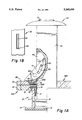
In the drawing, the FIGURE shows an axial, partly cross-sectional view of a hindrance means according to the invention.
The surface of the ground is identified with the reference numeral 400.
A tubular part (10) is mounted in the ground.
The flange 12 has a seam 15. In this seam a hindrance means 16 is immersed, which reaches down in the sleeve 11. This hindrance means 16 is turned with a stepped form 17. The hindrance means 16 is connected to the flange 12 through a screw joint 18.
In the seam 15, on top of the hindrance means 16, is mounted a packing box 200.
A packing flange 19 has a seam 20, in which seam a scraper ring 300 is arranged, and underneath the scraper ring a washer 21 is mounted, which holds the scraper ring 300 in place.
The flanges 12,19 are connected to each other through a screw joint 22.
A post 30 made of solid material passes with a slip fit through the packing box 200 and the scraper ring 300 down into the sleeve 11 having a larger inside diameter than the post 30.
A cylindrical guide body 31 is arranged having an outside diameter corresponding to the inner diameter of the sleeve 11 and prevents removal of the post 30 from part 10 by abutting the hindrance means 16.
The sleeve 11 is deep enough for inserting the post therein, whereby the cap 70 on the post will rest on the flange 19 and/or the surface of the ground 400.
The cap 70 can be convex on the upper side and be provided with a lifting means 71, such as a pulling ring, which is immersed in a groove in the cap 70, which pulling ring is provided with a holder acting as a hinge.
The post 30 has an axial slot 40 and a catch 41, which through a groove 42 in the catch 41 is guided by a pin 43, which prevents the catch 41 from sliding completely out of the slot 40.
The catch is retractable into the slot 40 to an inner position, where it is accomodated inside the outer diameter of the post, and it is extendable by its own weight. When the catch 41 has passed the upper part of the scraping ring 300/the surface of the ground 400, the catch falls out under its own weight and rests on the packing flange 19 and the surface of the ground 400, whereby the opening 44 is exposed. A padlock is mounted with its clamp through the opening 44 and prevents depression of the post 30 into the sleeve 10.
The embodiment shown in the drawing has proved to fullfill all practical demands put on a hindrance means, and thereby eliminates all disadvantages and defects associated with previously known embodiments of hindrance means.
Claims (2)
1. A means at a parking lot having at its front end a barrier and, at its back end, a hindrance means (10,30) which is raisable from a retired position and which is lockable in a raised position, whereby the hindrance means (10,30) comprises a tubular part, which is recessedly mounted in the ground at the parking lot, and a post (30), which is telescopically mounted in said tubular part, which post is connected to a guide body (31) preventing the post (30) from being dragged out of a sleeve (11) by a second hindrance means (16), characterized in that the post (30) comprises a slot (40) wherein a catch (41) is pivotally mounted on the post between an inner position, wherein the catch lies within the cross section of the post, and an outer position in which the catch (41) projects outside said cross section and prevents the post from being pushed down from its raised, locked position, and in that an opening (44) is arranged in the projecting part of the catch (41) in order to receive a padlock clamp.
2. Means according to claim 1, characterized in that the slot (40) is arranged substantially axially in the, preferably solid post (30).
Applications Claiming Priority (3)
| Application Number | Priority Date | Filing Date | Title |
|---|---|---|---|
| SE9101447A SE9101447L (en) | 1991-05-14 | 1991-05-14 | STEEL PROTECTION DEVICE AT PARKING PLACE INCLUDING A POST WITH SWINGABLE SAVING TUNING |
| SE9101447 | 1991-05-14 | ||
| PCT/SE1992/000301 WO1992020867A1 (en) | 1991-05-14 | 1992-05-08 | Parking place obstruction |
Publications (1)
| Publication Number | Publication Date |
|---|---|
| US5365695A true US5365695A (en) | 1994-11-22 |
Family
ID=20382720
Family Applications (1)
| Application Number | Title | Priority Date | Filing Date |
|---|---|---|---|
| US08/146,019 Expired - Fee Related US5365695A (en) | 1991-05-14 | 1992-05-08 | Parking place obstruction |
Country Status (7)
| Country | Link |
|---|---|
| US (1) | US5365695A (en) |
| EP (1) | EP0584173B1 (en) |
| AT (1) | ATE134238T1 (en) |
| CA (1) | CA2108573C (en) |
| DE (1) | DE69208361T2 (en) |
| SE (1) | SE9101447L (en) |
| WO (1) | WO1992020867A1 (en) |
Cited By (2)
| Publication number | Priority date | Publication date | Assignee | Title |
|---|---|---|---|---|
| US6289633B1 (en) | 2000-03-10 | 2001-09-18 | Gwyn Lowe | Parking place obstruction |
| US20080075530A1 (en) * | 2006-09-22 | 2008-03-27 | The Hong Kong Polytechnic University | Bollard with connecting mechanisms for connecting railings |
Families Citing this family (3)
| Publication number | Priority date | Publication date | Assignee | Title |
|---|---|---|---|---|
| GB2287495B (en) * | 1994-03-15 | 1997-11-19 | William Godfrey Lukes Barton | Security post |
| GB2299604A (en) * | 1995-04-07 | 1996-10-09 | Jonathan Mark Nigel Grosvenor | Removable security bollard |
| CN107326832B (en) * | 2017-07-18 | 2020-07-21 | 平顶山市华安电气有限公司 | Intelligent transportation obstacle stake |
Citations (6)
| Publication number | Priority date | Publication date | Assignee | Title |
|---|---|---|---|---|
| US3564769A (en) * | 1968-03-28 | 1971-02-23 | Arthur G Wilson | Anti-theft device |
| US3660935A (en) * | 1970-03-26 | 1972-05-09 | Patrick R Boots | Vehicle parking space locking device |
| US4003161A (en) * | 1976-03-01 | 1977-01-18 | Collins Wesley A | Mechanical barrier |
| US4576508A (en) * | 1984-12-06 | 1986-03-18 | Dickinson Harry D | Bollard trafficway barrier and vehicle arrest system |
| FR2621625A1 (en) * | 1987-12-07 | 1989-04-14 | Clapier Georges | Autonomous bollard of variable height |
| US5054237A (en) * | 1990-07-16 | 1991-10-08 | Rockford Ornamental Iron Incorporated | Vehicle safety barrier |
Family Cites Families (1)
| Publication number | Priority date | Publication date | Assignee | Title |
|---|---|---|---|---|
| GB1256889A (en) * | 1968-06-20 | 1971-12-15 |
-
1991
- 1991-05-14 SE SE9101447A patent/SE9101447L/en not_active IP Right Cessation
-
1992
- 1992-05-08 AT AT92910422T patent/ATE134238T1/en not_active IP Right Cessation
- 1992-05-08 CA CA002108573A patent/CA2108573C/en not_active Expired - Fee Related
- 1992-05-08 WO PCT/SE1992/000301 patent/WO1992020867A1/en active IP Right Grant
- 1992-05-08 US US08/146,019 patent/US5365695A/en not_active Expired - Fee Related
- 1992-05-08 EP EP92910422A patent/EP0584173B1/en not_active Expired - Lifetime
- 1992-05-08 DE DE69208361T patent/DE69208361T2/en not_active Expired - Fee Related
Patent Citations (6)
| Publication number | Priority date | Publication date | Assignee | Title |
|---|---|---|---|---|
| US3564769A (en) * | 1968-03-28 | 1971-02-23 | Arthur G Wilson | Anti-theft device |
| US3660935A (en) * | 1970-03-26 | 1972-05-09 | Patrick R Boots | Vehicle parking space locking device |
| US4003161A (en) * | 1976-03-01 | 1977-01-18 | Collins Wesley A | Mechanical barrier |
| US4576508A (en) * | 1984-12-06 | 1986-03-18 | Dickinson Harry D | Bollard trafficway barrier and vehicle arrest system |
| FR2621625A1 (en) * | 1987-12-07 | 1989-04-14 | Clapier Georges | Autonomous bollard of variable height |
| US5054237A (en) * | 1990-07-16 | 1991-10-08 | Rockford Ornamental Iron Incorporated | Vehicle safety barrier |
Cited By (3)
| Publication number | Priority date | Publication date | Assignee | Title |
|---|---|---|---|---|
| US6289633B1 (en) | 2000-03-10 | 2001-09-18 | Gwyn Lowe | Parking place obstruction |
| US20080075530A1 (en) * | 2006-09-22 | 2008-03-27 | The Hong Kong Polytechnic University | Bollard with connecting mechanisms for connecting railings |
| US7722283B2 (en) * | 2006-09-22 | 2010-05-25 | The Hong Kong Polytechnic University | Bollard with connecting mechanisms for connecting railings |
Also Published As
| Publication number | Publication date |
|---|---|
| SE467310B (en) | 1992-06-29 |
| CA2108573C (en) | 2001-07-03 |
| DE69208361T2 (en) | 1996-10-10 |
| EP0584173A1 (en) | 1994-03-02 |
| CA2108573A1 (en) | 1992-11-15 |
| SE9101447L (en) | 1992-06-29 |
| DE69208361D1 (en) | 1996-03-28 |
| WO1992020867A1 (en) | 1992-11-26 |
| ATE134238T1 (en) | 1996-02-15 |
| SE9101447D0 (en) | 1991-05-14 |
| EP0584173B1 (en) | 1996-02-14 |
Similar Documents
| Publication | Publication Date | Title |
|---|---|---|
| DE19930524B4 (en) | In a motor vehicle mountable device for holding a drinking vessel | |
| USRE26779E (en) | Street boundary post | |
| US3857575A (en) | Security trailer hitching post | |
| US5104138A (en) | Trailer hitch assembly with readily removable trailer hitch | |
| US20070108729A1 (en) | Invertible gooseneck trailer hitch mechanism | |
| US5365695A (en) | Parking place obstruction | |
| CA2075125C (en) | Security device for securing a spare tire | |
| AU640037B2 (en) | Two stage automobile steering lock | |
| US5040924A (en) | Concealable anchor | |
| US5725234A (en) | Ball-type coupler for trailers and the like | |
| EP1074428B1 (en) | Support for a beverage container for automotive vehicles | |
| DE29920019U1 (en) | Device for holding beverage cans | |
| GB2024128A (en) | Vehicle anti-theft device | |
| GB2443631A (en) | Retractable bollard assembly | |
| US4373303A (en) | In-ground trailer post assembly | |
| US5251876A (en) | Drive for a tire lift mechanism and method for assembling same | |
| US5635653A (en) | Ground water sampling device | |
| US6289633B1 (en) | Parking place obstruction | |
| FR2392172A1 (en) | RETRACTABLE DAM POST FOR MOTOR VEHICLES | |
| FR2851586A1 (en) | Retractable terminal for reserving access to authorized vehicle, has movable part with segments encased telescopically one into another, where central segment is connected to telescopic jack to control return/exit of segments | |
| GB2247266A (en) | Security post | |
| FR2568906A1 (en) | Car park barrier | |
| EP0524901B1 (en) | Retractable guard-rail for road-unit especially vehicle-carrier | |
| GB2291089A (en) | Retractable post assembly | |
| AU766562B2 (en) | A jockey wheel |
Legal Events
| Date | Code | Title | Description |
|---|---|---|---|
| FEPP | Fee payment procedure |
Free format text: PAYOR NUMBER ASSIGNED (ORIGINAL EVENT CODE: ASPN); ENTITY STATUS OF PATENT OWNER: SMALL ENTITY |
|
| FPAY | Fee payment |
Year of fee payment: 4 |
|
| REMI | Maintenance fee reminder mailed | ||
| LAPS | Lapse for failure to pay maintenance fees | ||
| STCH | Information on status: patent discontinuation |
Free format text: PATENT EXPIRED DUE TO NONPAYMENT OF MAINTENANCE FEES UNDER 37 CFR 1.362 |
|
| FP | Lapsed due to failure to pay maintenance fee |
Effective date: 20021122 |