US5363682A - Four-roller type sizing mill apparatus for producing round steel rods - Google Patents
Four-roller type sizing mill apparatus for producing round steel rods Download PDFInfo
- Publication number
- US5363682A US5363682A US07/982,982 US98298292A US5363682A US 5363682 A US5363682 A US 5363682A US 98298292 A US98298292 A US 98298292A US 5363682 A US5363682 A US 5363682A
- Authority
- US
- United States
- Prior art keywords
- rollers
- pair
- roller
- rolling
- facing rollers
- Prior art date
- Legal status (The legal status is an assumption and is not a legal conclusion. Google has not performed a legal analysis and makes no representation as to the accuracy of the status listed.)
- Expired - Fee Related
Links
- 238000004513 sizing Methods 0.000 title claims abstract description 33
- 229910000831 Steel Inorganic materials 0.000 title claims abstract description 13
- 239000010959 steel Substances 0.000 title claims abstract description 13
- 238000005096 rolling process Methods 0.000 claims abstract description 141
- 239000000463 material Substances 0.000 claims abstract description 67
- 238000000034 method Methods 0.000 description 37
- 230000008901 benefit Effects 0.000 description 9
- 238000002474 experimental method Methods 0.000 description 5
- 230000008878 coupling Effects 0.000 description 4
- 238000010168 coupling process Methods 0.000 description 4
- 238000005859 coupling reaction Methods 0.000 description 4
- 230000008859 change Effects 0.000 description 3
- 230000009467 reduction Effects 0.000 description 3
- 230000001360 synchronised effect Effects 0.000 description 2
- 238000011144 upstream manufacturing Methods 0.000 description 2
- 230000015572 biosynthetic process Effects 0.000 description 1
- 238000010276 construction Methods 0.000 description 1
- 230000003247 decreasing effect Effects 0.000 description 1
- 230000007547 defect Effects 0.000 description 1
- 230000006866 deterioration Effects 0.000 description 1
- 230000002542 deteriorative effect Effects 0.000 description 1
- 230000000694 effects Effects 0.000 description 1
- 238000010438 heat treatment Methods 0.000 description 1
- 238000012423 maintenance Methods 0.000 description 1
- 238000012986 modification Methods 0.000 description 1
- 230000004048 modification Effects 0.000 description 1
- 238000002360 preparation method Methods 0.000 description 1
- 238000012545 processing Methods 0.000 description 1
- 102200082816 rs34868397 Human genes 0.000 description 1
- 239000002436 steel type Substances 0.000 description 1
- 238000012360 testing method Methods 0.000 description 1
Images


Classifications
-
- B—PERFORMING OPERATIONS; TRANSPORTING
- B21—MECHANICAL METAL-WORKING WITHOUT ESSENTIALLY REMOVING MATERIAL; PUNCHING METAL
- B21B—ROLLING OF METAL
- B21B19/00—Tube-rolling by rollers arranged outside the work and having their axes not perpendicular to the axis of the work
- B21B19/02—Tube-rolling by rollers arranged outside the work and having their axes not perpendicular to the axis of the work the axes of the rollers being arranged essentially diagonally to the axis of the work, e.g. "cross" tube-rolling ; Diescher mills, Stiefel disc piercers or Stiefel rotary piercers
- B21B19/06—Rolling hollow basic material, e.g. Assel mills
- B21B19/10—Finishing, e.g. smoothing, sizing, reeling
-
- B—PERFORMING OPERATIONS; TRANSPORTING
- B21—MECHANICAL METAL-WORKING WITHOUT ESSENTIALLY REMOVING MATERIAL; PUNCHING METAL
- B21B—ROLLING OF METAL
- B21B13/00—Metal-rolling stands, i.e. an assembly composed of a stand frame, rolls, and accessories
- B21B13/08—Metal-rolling stands, i.e. an assembly composed of a stand frame, rolls, and accessories with differently-directed roll axes, e.g. for the so-called "universal" rolling process
- B21B13/12—Metal-rolling stands, i.e. an assembly composed of a stand frame, rolls, and accessories with differently-directed roll axes, e.g. for the so-called "universal" rolling process axes being arranged in different planes
-
- B—PERFORMING OPERATIONS; TRANSPORTING
- B21—MECHANICAL METAL-WORKING WITHOUT ESSENTIALLY REMOVING MATERIAL; PUNCHING METAL
- B21B—ROLLING OF METAL
- B21B1/00—Metal-rolling methods or mills for making semi-finished products of solid or profiled cross-section; Sequence of operations in milling trains; Layout of rolling-mill plant, e.g. grouping of stands; Succession of passes or of sectional pass alternations
- B21B1/16—Metal-rolling methods or mills for making semi-finished products of solid or profiled cross-section; Sequence of operations in milling trains; Layout of rolling-mill plant, e.g. grouping of stands; Succession of passes or of sectional pass alternations for rolling wire rods, bars, merchant bars, rounds wire or material of like small cross-section
- B21B1/18—Metal-rolling methods or mills for making semi-finished products of solid or profiled cross-section; Sequence of operations in milling trains; Layout of rolling-mill plant, e.g. grouping of stands; Succession of passes or of sectional pass alternations for rolling wire rods, bars, merchant bars, rounds wire or material of like small cross-section in a continuous process
-
- B—PERFORMING OPERATIONS; TRANSPORTING
- B21—MECHANICAL METAL-WORKING WITHOUT ESSENTIALLY REMOVING MATERIAL; PUNCHING METAL
- B21B—ROLLING OF METAL
- B21B2203/00—Auxiliary arrangements, devices or methods in combination with rolling mills or rolling methods
- B21B2203/18—Rolls or rollers
- B21B2203/182—Fluid driven rolls or rollers
-
- B—PERFORMING OPERATIONS; TRANSPORTING
- B21—MECHANICAL METAL-WORKING WITHOUT ESSENTIALLY REMOVING MATERIAL; PUNCHING METAL
- B21B—ROLLING OF METAL
- B21B31/00—Rolling stand structures; Mounting, adjusting, or interchanging rolls, roll mountings, or stand frames
- B21B31/16—Adjusting or positioning rolls
- B21B31/18—Adjusting or positioning rolls by moving rolls axially
-
- B—PERFORMING OPERATIONS; TRANSPORTING
- B21—MECHANICAL METAL-WORKING WITHOUT ESSENTIALLY REMOVING MATERIAL; PUNCHING METAL
- B21B—ROLLING OF METAL
- B21B31/00—Rolling stand structures; Mounting, adjusting, or interchanging rolls, roll mountings, or stand frames
- B21B31/16—Adjusting or positioning rolls
- B21B31/20—Adjusting or positioning rolls by moving rolls perpendicularly to roll axis
- B21B31/22—Adjusting or positioning rolls by moving rolls perpendicularly to roll axis mechanically, e.g. by thrust blocks, inserts for removal
- B21B31/26—Adjusting eccentrically-mounted roll bearings
-
- B—PERFORMING OPERATIONS; TRANSPORTING
- B21—MECHANICAL METAL-WORKING WITHOUT ESSENTIALLY REMOVING MATERIAL; PUNCHING METAL
- B21B—ROLLING OF METAL
- B21B35/00—Drives for metal-rolling mills, e.g. hydraulic drives
- B21B35/10—Driving arrangements for rolls which have only a low-power drive; Driving arrangements for rolls which receive power from the shaft of another roll
Definitions
- the present invention relates to a four-roller type rolling mill apparatus for sizing bar and rod materials to give them round sectional shapes. More particularly, the present invention relates to a four-roller type sizing mill which achieves an increased maximum rolling draft for sizing while retaining a high sizing precision.
- a heated steel material is continuously rolled into a round rod having a desired size by a line of a plurality of rolling mills including roughing mills and finishing mills having grooved caliber rollers. Sizing mills are usually used at the final stages in the finishing mills.
- the rolling methods using sizing mills fall into three types on the basis of the number of rollers in the first stand of the sizing mills. These types are the two-roller method, three-roller method and four-roller method, as shown in FIGS. 10(a), 10(b) and 10(c), respectively.
- a rolling material w is rolled through passes formed by the grooves 20a, 22a and 25a of the rollers belonging to the respective roller units which are set with respect to different rolling directions, for example, through a pass between rollers 20 and 21 and then a pass between rollers 20' and 21' in FIG. 10(a).
- rollers 20 to 28 have grooves 20a, 22a and 25a having predetermined sectional shapes.
- Japanese Patent Application Laid-Open No. 1-202302 discloses a two-roller sizing method in which a material is rolled through three passes each of which is formed by two rollers and has rolling directions different from those of the other two passes.
- Japanese Patent Application Laid-Open No. 63-43072 discloses a three-roller sizing method in which a material is rolled through three passes each of which is formed by three rollers and has rolling directions different from those of the other two passes.
- Japanese Patent Application Laid-Open No. 62-199206 discloses a four-roller sizing method in which a material is rolled through two passes each of which is formed by four rollers and has rolling directions different from those of the other pass.
- FIGS. 10(a) to 10(c) Three rolling methods as shown in FIGS. 10(a) to 10(c) were tested to compare their performances.
- the same type of rolling material w having a diameter d of 50 mm was sized by each of the three methods.
- the shapes of the grooves 20a, 22a and 25a of the rollers used to form the final-stage passes were as shown in FIGS. 11(a), 11(b) and 11(c), respectively.
- the sectional views of the obtained round steel rods are shown in FIGS. 12(a), 12(b) and 12(c).
- the two-roller method produced a sectional shape of a quadrangular circle as shown in FIG. 12(a).
- the three-roller method produced a sectional shape of a hexagonal circle as shown in FIG. 12(b).
- the four-roller method produced a sectional shape of an octagonal circle as shown in FIG. 12(c).
- the graph in FIG. 14 is based upon these results, indicating the relation between diameter differences and rolling draft as well as the over-filling limits by arrows ⁇ .
- the four-roller method achieves a higher sizing-precision than the other methods with respect to the same rolling draft, but the four-roller method results in over-filling with less rolling draft than the other two methods.
- the four-roller method can perform sizing only in limited ranges of rolling drafts.
- the two-roller method fails to achieve a high sizing-precision, but can perform sizing in a wider range of rolling drafts than the other two methods, without suffering over-filling.
- FIG. 15 indicates the relation between the rolling reduction and the width expansion of round steel rods obtained by the three methods, the width expansion being obtained on the basis of the following calculation: [(the width of material after rolling--the width of material before rolling)/the width of material before rolling] ⁇ 100.
- the two-roller method causes a greater width expansion than the other two methods
- the three-roller method causes a greater width expansion than the four-roller method, with respect to the same rolling reduction.
- the sizing-precision in the two-roller method is subject to greater deterioration.
- the four-roller method has, again, advantages with regard to sizing precision.
- the two-roller method is more useful than the other two methods because the two-roller method allows a greater range of rolling drafts for sizing. If the sizing precision is critical, the four-roller method is more advantageous than the other two methods.
- rollers of the four-roller type mills can perform sizing only in a limited range of rolling drafts, the rollers must be changed frequently in order to provide a desired rolling draft. To change rollers, the rolling operation must be stopped, thus significantly deteriorating operating efficiency.
- the structure of a rolling mill becomes more complicated in the order of the two-roller method, the three-roller method and the four-roller method. More specifically, as the number of roller driving devices increases, adjustment of the roller gaps and adjustment of position of the rollers along their own axes become more delicate.
- a known four-roller type mill must have four roller-driving devices because each of the four rollers needs a torque to rotate. Further, these four driving devices of the four-roller type mill must be electrically synchronized. Thus, a known four-roller type mill requires a great number of parts and components and, therefore, a complicated structure, inevitably becoming bulky and expensive.
- roller driving device including motors and spindles must be removed from the main body. Still further, because the roller driving device including motors are provided around the rollers, changing or maintaining the rollers is not very easy.
- the four-roller method has an advantage in improving sizing-precision, it has several problems, such as the requirement for the complicated structure or frequently changing rollers. Therefore, the four-roller method has not been widely used in sizing mills.
- an object of the present invention is to provide a novel four-roller type sizing mill in which a unit of rollers achieves a wide range of rolling drafts for sizing and a simplified structure to facilitate changing and maintaining the rollers.
- the present invention provides a four-roller type sizing mill apparatus for forming round steel rods comprising two four-roller mills each having two pair of facing rollers.
- One pair of facing rollers is arranged in a rolling direction perpendicular to the rolling direction of the other pair of facing rollers.
- the two four-roller mills are arranged in line, with the rolling direction of one of the two four-roller mills being shifted by 45° from the rolling direction of the other four-roller mill.
- the two pair of facing rollers of a first four-roller mill of the two four-roller mills are positioned closer to a rolling material inlet and are separate from each other by a distance which is greater than zero and not greater than five times a projected contact length of one of the pair of facing rollers positioned closer to the rolling material inlet.
- the distance is measured between a first standard straight line which passes through the centers of one of the pair of facing rollers and lies on a plane parallel to the side surfaces of the same pair of facing rollers and a second standard straight line obtained by projecting the axes of the other pair of facing rollers onto the above-mentioned plane.
- FIG. 1 is a schematic front view of a four-roller type rolling mill apparatus according to an embodiment of the present invention.
- FIG. 2 is a schematic side view of the four-roller type rolling mill apparatus according to the embodiment of the present invention.
- FIG. 3 schematically illustrates the steps of a rolling process according to the present invention.
- FIG. 4 is a schematic front view of a four-roller type rolling mill apparatus according to another embodiment of the present invention.
- FIG. 5 is a graph indicating the relation between the width expansion and the ratio (L/l d ) of the distance L between the two pair of rollers of a four-roller type mill to the projected contact length l d of one of the pair of rollers being closer to the inlet of rolling material.
- FIG. 6 is a graph indicating the relation between the distance L and the maximum rolling draft.
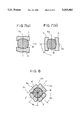
- FIGS. 7(a) and 7(b) are enlarged sectional views of the pass portions of the upstream four-roller type mill, taken along lines A--A of FIG. 2.
- FIG. 8 is an enlarged view of the pass portion of the downstream four-roller type mill, taken along the line B--B of FIG. 2.
- FIG. 9 is a graph indicating the relation between the average diameters and diameter differences of the individual round steel rods formed by the apparatus of the invention.
- FIGS. 10(a), 10(b) and 10(c) are schematic illustrations of examples of known rolling mill apparatuses of two-roller type, three-roller type and four-roller type, respectively.
- FIGS. 11(a) to 11(c) schematically illustrate the groove shapes of the rollers used in experiments.
- FIGS. 12(a) to 12(c) schematically illustrate the ranges of diameters of round rods formed by different types of rolling mill apparatuses.
- FIG. 13 schematically illustrates the points of over-filling limit which were defined in the experiments.
- FIG. 14 is a graph indicating the relations between rolling draft and diameter differences according to the known art.
- FIG. 15 is a graph indicating the relations between rolling reduction and width expansion according to the known art.
- FIG. 3 illustrates, generally, the steps of a rolling process according to the present invention.
- a furnace 14 for heating a rolling material to a high temperature is placed at an upstream position. Downstream therefrom, a plurality of two-roller roughing mills 15 are arranged in line, with the rolling direction of two neighboring two-roller mills being substantially perpendicular to each other.
- Two stands of a four-roller mill according to the present invention, that is, the first stand 16 and the second stand 17, are provided at a downstream position.
- An arrow P in the drawing indicates the conveying direction or the pass line of a material.
- the first stand 16 of the four-roller mills of the present invention will be described with reference to FIG. 1.
- a pair of rollers 1 and 2 are arranged in a unit 10 so that grooves 1a and 2a of the rollers 1 and 2 are vertically aligned and face each other.
- Another pair of rollers 3 and 4 are arranged in the unit 10 so that the grooves 3a and 4a of the rollers 3 and 4 are horizontally aligned and face each other.
- These four rollers 1 to 4 form a substantially circular roller gap.
- Shafts 1b to 4b of the rollers 1 to 4 may be rotatably connected to the unit 10 by four-roller type mill of roller neck bearings (not shown), respectively.
- a first standard straight line O 1 which passes through the centers C1 and C2 of a pair of rollers 1 and 2 and lies on a plane parallel to the side surfaces of the pair of rollers 1 and 2 (e.g., a plane of the sheet of the drawing) is separated by a distance L from a second standard straight line O 2 obtained by projecting the axes of the other pair of rollers 3 and 4.
- This distance L will be referred to as "the distance L" hereinafter.
- the distance L is 0 in the conventional four-roller type mills, whereas the four-roller type mill of the present invention has two pair of rollers which are separated from each other (L>0).
- a rolling material is rolled by a first pair of rollers and then by a second pair of rollers which are placed downstream from the first pair of rollers.
- the advantages of both the two-roller type mill and the four-roller type mill can be achieved by appropriately adjusting the distance L. More specifically, the for-sizing rolling draft of a unit of rollers is increased compared with the conventional four-roller type mill (an advantage of the two-roller type mill). Further, sizing-precision is improved compared with the conventional two-roller type mill (an advantage of the four-roller type mill).
- this four-roller type mill becomes more like two conventional two-roller type mills.
- Experimental rolling was performed by using four-roller type mills having different distances L, and the width expansions of the resulting round steel rods were measured.
- the relation between the width expansions and the ratios (L/l d ) of the distances L to the projected contact lengths l d of one of the pair of rollers closer to the inlet of rolling materials was studied.
- a projected contact length l d is defined as the length of an area obtained by projecting the contact area between the roller 1 and the rolling material onto the pass line P in FIG. 2.
- FIG. 5 illustrates that, if the ratio is in the range E 1 according to the present invention, that is, L/l d ⁇ 5, the width expansion of a rolling material can be maintained at low levels.
- the two pair of rollers of the four-roller type mill of the present invention are comparatively close to each other, the four-roller type mill achieves the advantage of the conventional four-roller type mill, that is, low width expansion.
- the ratio is out of the range E 1 according to the present invention, in other words, L/l d >5 (range E 2 )
- the width expansion becomes significantly great.
- the two pair of rollers of the four-roller type mill are relatively far away from each other and the four-roller type mill becomes more like two conventional two-roller type mills causing high width expansion.
- FIG. 6 is a graph indicating the relation between the distances L and the maximum rolling drafts.
- the solid-line curve a 1 was obtained when the radius of curvature of the groove of the rollers (denoted by R 3 in FIG. 11(C)) was 25 mm.
- the broken-line curve a 2 was obtained when the radius of curvature R 3 was 15 mm.
- the straight lines b1 and b2 indicate the maximum rolling drafts of conventional three-roller type mills in which the radius of curvature of the grooves are 25 mm and 15 mm, respectively.
- the lines b1 and b2 were also obtained in experiments.
- FIG. 6 indicates that the four-roller type mill of the present invention will achieve maximum rolling draft for sizing as great as or greater than that achieved by the conventional three-roller type mill if the distance L ⁇ 30 mm.
- the distance L is appropriately determined within the above-mentioned range, considering various conditions such as a certificated level of dimensional tolerance of the products or a target level of rolling efficiency. After many rolling experiments, the inventors have found that the suitable range of the distance L is 30 mm ⁇ L ⁇ two times the projected contact length (2l d ).
- Each of the shafts 1b and 2b of the rollers 1 and 2 whose grooves are vertically aligned is connected at one end thereof to an end of a spindle 5a and 5b by a coupling 6a and 6b, respectively.
- the other ends of the spindles 5a and 5b are connected to pinion gears 8a and 8b by couplings 7a and 7b, respectively.
- the two pinion gears 8a and 8b are engaged with each other, and a pinion gear 8b is connected to a shaft of a driving motor 9.
- the roller driving device is comprised of: the couplings 6a, 6b, 7a, 7b; the spindles 5a and 5b; the pinion gears 8a and 8b; and the driving motor 9.
- the pinion gears 8a and 8b are rotatably supported in a pinion stand 11.
- FIG. 1 shows the shafts 1b and 2b of the rollers 1 and 2 which are separated from the couplings 6a and 6b.
- the pair of rollers 3 and 4 whose grooves are horizontally aligned are rotatably connected to shafts 3b and 4b, respectively, but not connected to driving sources such as motors.
- the four-roller mill further comprises a screw down device (not shown) which adjusts the width of the gap of the facing rollers by using eccentric means, such as an eccentric sleeve, for adjusting the roller gap so that the gap becomes symmetric about the pass line.
- An axial position adjusting device such as a screw nut type adjusting device, may be included for correcting a shift of the center of the pass of the facing rollers, the shift being along the axes of the rollers.
- the second stand 17 of the four-roller type mill that is, the stand closer to the outlet of the rolling material, is constructed substantially in the same manner as the first stand 16, except that the roller axes are shifted 45° from those of the first stand 16 and that the distance L is zero.
- a rolling material w is heated to a high temperature by the furnace 14, rolled into a substantially circular sectional shape by the array 15 of the two-roller type mills and then conveyed into the inlet side of the first stand 16 of the four-roller type mill.
- the gap between the two pair of rollers 1 to 4 is adjusted in accordance with the product by the screw down device (not shown), thereby suitably determining the rolling force of the rollers applied to the rolling material. Further, shifting of the centers of the passes 1a to 4a of the rollers are corrected by the axial position adjusting device (not shown). Torque is supplied from the driving motor 9 and transmitted by the pinion gears 8a and 8b and spindles 5a and 5b to the shafts of the vertically aligned rollers 1 and 2. Thus, the rollers 1 and 2 rotate, mechanically synchronized by the pinion gears 8a and 8b which are engaged with each other. The horizontally aligned rollers 3 and 4 are not rotated by driving means.
- the structure is simplified because the rollers 3 and 4 of the first and second stands 16 and 17 of the four-roller type mill are not connected to driving motors or spindles. Further, the simplified structure creates an increased working space for the adjustments of the roller gaps and the position of a roller along its axis, thus facilitating these operations.
- the rollers may be easily changed because the unit 10 is separable from the spindles 5a and 5b by moving the unit 10 toward the left in FIG. 1 (in the direction indicated by the arrow A). Maintenance may also be more easily performed.
- rollers 1 and 2 are used to drive the vertically-aligned pair of rollers 1 and 2 in the above embodiment, two driving motors may be used to drive the rollers 1 and 2, respectively. Further, the horizontally-aligned rollers 3 and 4 may be driven instead of the rollers 1 and 2.
- the rollers 3 and 4 are not connected to a driving source. This may cause a problem, however. If the rolling force is set to a certain level or higher by the screw down device, the front end portion of a rolling material may hit the groove surface of the not-rotated rollers 3 and 4 too strongly. Such a strong force may cause damage to the groove surfaces of the rollers 3 and 4. Naturally, a flaw on the groove surface of a roller causes damage to the surface of the rolled rod.
- the shafts 3b and 4b of the horizontally-aligned rollers 3 and 4 are connected to small motors 12 and 12, respectively, according to another embodiment as shown in FIG. 4.
- the small motors 12 are connected to the unit 10 and thus form pre-rotating devices.
- the small motors provide the rollers 3 and 4 with a torque just large enough to rotate the rollers 3 and 4 when the rollers 3 and 4 are free, that is, when the rollers 3 and 4 are not rolling a material.
- the pre-rotating devices including the small motors 12 rotate the rollers 3 and 4 in the same direction and at substantially the same rotational speed as those of the vertically-aligned rollers 1 and 2 which are driven by the roller driving device.
- the rollers 3 and 4 are rotated at substantially the same speed as the conveying speed of the rolling material by the small motors 12 (which provide torque not so large as to rotate the rollers 3 and 4 for rolling but just large enough to rotate them when they are free), the front end of a rolling material does not strongly hit but softly contacts the groove surfaces of the rollers 3 and 4 even if the rolling force is set at a high level. Thus, the possibility of forming flaws on or damage to the groove surfaces of the rollers 3 and 4 is substantially eliminated.
- the rolling material is conveyed from the inlet side to the outlet side of the four-roller type mill by the rolling torque of the vertically-aligned rollers 1 and 2.
- the horizontally-aligned rollers 3 and 4 are rotated, in effect, by the movement of the rolling material; not by the torque provided by the small motors 12, which is not large enough for rolling.
- the pre-rotating devices including the motors 12 can be made small. The reduced size of these devices leaves increased working space for changing and maintaining the rollers, thus facilitating these operations.
- the small motors 12 may be disconnected from the horizontally-aligned rollers 3 and 4 after the front end portion of a rolling material w is bitten in the gaps between the rollers 1 to 4. After that, the rollers 3 and 4 are rotated solely by the movement of the rolling material w.
- the pre-rotating devices for rotating the horizontally-aligned rollers 3 and 4 may be known pre-rotating devices, such as hydraulic or pneumatic turbines.
- the rotation of the rollers 3 and 4 driven by the pre-rotating devices may be controlled at substantially the same speed as the rotation of the rollers 1 and 2 driven by the roller driving device, either by providing means, such as a rotation detecting sensor, in the driving motor 9 for electrically synchronizing the rotations of the two pair of rollers or by pre-setting the pre-rotating devices so that the devices rotate at a predetermined speed which is found most suitable from experience.
- the pre-rotating devices for rotating the pair of rollers which are not driven by the roller driving device may be provided with one-way clutches 13, as shown in FIG. 4.
- the one-way clutches 13 do not transmit torque from the small motors 12 to the rollers 3 and 4 but freely rotate while a rolling material w is being rolled at a sufficiently high speed. When the rolling speed of the rolling material w is decreased, the one-way-clutches 13 engage to transmit the torque of the small motors 12 to the rollers 3 and 4, thus helping to convey the rolling material w.
- FIG. 2 is a schematic side view of the four-roller type mill of the present invention.
- FIGS. 7(a) and 7(b) are enlarged sectional views of the pass portions taken along line A--A of FIG. 2.
- FIG. 8 is an enlarged sectional view of the pass portion taken along line B--B of FIG. 2.
- two stands 16 and 17 of the four-roller type mill were arranged along the pass line P. Each stand had four rollers.
- One pair of rollers 1 and 2 of the first stand 16 were set to vertically roll a rolling material w, and the other pair of rollers 3 and 4 were set to horizontally roll the rolling material w.
- the two pair of rollers were separated from each other by a distance L defined as follows.
- the distance L is measured between a first standard straight line O 1 which passes through the centers C1 and C2 of the pair of rollers 1 and 2 and lies on a plane parallel to the side surfaces of the pair of rollers 1 and 2 (e.g., the plane of the drawing) and a second standard straight line O 2 obtained by projecting the axes of the other pair of rollers 3 and 4 onto the above-mentioned plane.
- the first stand 16 has four rollers, this stand may be viewed as a unit of two two-roller mills leaving the distance L therebetween: one two-roller mill having the pair of rollers 1 and 2 as shown in FIG. 7(a); and another two-roller mill having the pair of rollers 3 and 4 as shown in FIG. 7(b).
- the two pair of rollers 1' to 4' of the second stand 17 were arranged as shown in FIG. 8.
- the angle ⁇ 2 between a line O 4 indicating the rolling direction of a pair of rollers 1' and 2' and the line O 2 indicating the rolling direction of the pair of rollers 1 and 2 of the first stand was 45° .
- the angle ⁇ 3 between a line O 5 indicating the rolling direction of the other pair of rollers 3' and 4' and the line O 3 indicating the rolling direction of the pair of rollers 3 and 4 of the first stand was also 45° .
- rolling mills including the above-described first and second stands 16 and 17 of the four-roller type mill, rolling materials having substantially circular sectional shapes were rolled for sizing by a method according to the present invention, under the following conditions.
- the rolling materials having the above diameters were rolled with the rolling drafts of 1.0 to 5.0 mm, thus obtaining products having a wide variety of diameters compared with a conventional four-roller type mill, as shown in Table 1.
- the graph in FIG. 9 indicates the relation between the thus-obtained diameter differences and the average diameters of individual products (i.e., "diameters of products" in Table 1).
- the broken line T indicates the tolerance according to the Japanese Industrial Standard (JIS).
- the four-roller type sizing mill of this example of the present invention achieved a sizing-precision two times as high as the tolerance according to JIS, or even higher.
- two pair of rollers of a four-roller mill are arranged leaving a distance L therebetween (the distance L as defined above).
- the four-roller mill of the present invention achieves both the advantages of the conventional two-roller mill and the advantages of the conventional four-roller mill.
- a unit of four rollers can perform sizing with a widened range of rolling drafts while achieving a significantly high level of sizing precision.
- the four-roller type sizing mill of the present invention achieves a reduced size and a simplified structure.
- the reduced size and simplified structure allow an increased space for arrangement and adjustment of four rollers.
- the roller gaps and the positions of the rollers along their axes can be adjusted by a screw down device and an axial position adjusting device with an improved precision.
- the increased space around the rollers facilitates changing and maintaining the rollers.
- the front end of a rolling material does not strongly hit but softly contacts the groove surfaces of the non-driven rollers when the front end portion is bitten by the rollers. Formation of flaws on the groove surface is thus avoided.
Landscapes
- Engineering & Computer Science (AREA)
- Mechanical Engineering (AREA)
- Metal Rolling (AREA)
Abstract
Description
______________________________________
Rolling Conditions:
______________________________________
Steel Type            S45C
Rolling Temperature   850 to 900° C.
Diameters of Materials (mm)
                      21, 33, 44, 55
Diameter of Rollers   380 mm
Passes of Rollers (see FIG. 11(c))
Central Angles θ.sub.3 = 45°
Radii of Curvature R.sub.3 (mm)
                      10.0, 16.0, 21.5, 27.0
Rolling Draft         1.0 to 5.0 mm
Distance L            40 to 60 mm
(L/l.sub.d)           (1.5 to 4.4)
______________________________________
              TABLE 1
______________________________________
Diameters of           Diameters of
Materials      R.sub.3 Products
(mm)           (mm)    (mm)
______________________________________
21             10.0    20 to 16
33             16.0    32 to 28
44             21.5    43 to 39
55             27.0    54 to 50
______________________________________
Claims (2)
Applications Claiming Priority (4)
| Application Number | Priority Date | Filing Date | Title |
|---|---|---|---|
| JP31677891 | 1991-11-29 | ||
| JP3-316778 | 1991-11-29 | ||
| JP22006592A JP2589028B2 (en) | 1992-08-19 | 1992-08-19 | Sizing rolling method for round steel bars |
| JP4-220065 | 1992-08-19 |
Publications (1)
| Publication Number | Publication Date |
|---|---|
| US5363682A true US5363682A (en) | 1994-11-15 |
Family
ID=26523502
Family Applications (1)
| Application Number | Title | Priority Date | Filing Date |
|---|---|---|---|
| US07/982,982 Expired - Fee Related US5363682A (en) | 1991-11-29 | 1992-11-30 | Four-roller type sizing mill apparatus for producing round steel rods |
Country Status (3)
| Country | Link |
|---|---|
| US (1) | US5363682A (en) |
| KR (1) | KR950011311B1 (en) |
| DE (1) | DE69224725T2 (en) |
Cited By (16)
| Publication number | Priority date | Publication date | Assignee | Title |
|---|---|---|---|---|
| EP0689883A2 (en) | 1994-06-29 | 1996-01-03 | Kawasaki Steel Corporation | Roller cutting method and apparatus for a plural-roll rolling mill |
| US5743127A (en) * | 1994-12-28 | 1998-04-28 | Kawasaki Steel Corporation | Round steel bar guide apparatus and method |
| US5832765A (en) * | 1995-10-14 | 1998-11-10 | Daido Tokushuko Kabushiki Kaisha | Method and an apparatus for manufacturing wire |
| US6085565A (en) * | 1995-11-30 | 2000-07-11 | Daido Steel Co., Ltd. | Eight-roller type rolling mill and method of rolling using the mill |
| WO2000048756A1 (en) * | 1999-02-16 | 2000-08-24 | Kawasaki Steel Corporation | Wire rod rolling line |
| US6128939A (en) * | 1997-03-20 | 2000-10-10 | Techint Compagnia Tecnica Internazionale S.P.A. | Roll train and the relative rolling process with an improved yield |
| US6216517B1 (en) * | 1997-11-14 | 2001-04-17 | Voest Alpine Industieanlagenbau Gmbh | Precision-rolling process |
| US6442989B1 (en) * | 1999-08-19 | 2002-09-03 | Kawasaki Steel Corporation | Wire sizing rolling method |
| USRE38095E1 (en) * | 1998-10-19 | 2003-04-29 | Mario Fabris | Sizing roll stand for a steel mill |
| US20030167817A1 (en) * | 2000-09-20 | 2003-09-11 | Jurgen Seidel | Combined drive for a four-or-six-high rolling stand and an operating method for the same |
| US20030172704A1 (en) * | 2002-02-20 | 2003-09-18 | Sms Meer Gmbh | Rolling train for the rolling of wire and light steel sections |
| US6702525B2 (en) * | 2001-02-28 | 2004-03-09 | Kennametal Inc. | Cutting tool for a bar peeling operation |
| ITMI20082343A1 (en) * | 2008-12-30 | 2010-06-30 | Danieli Off Mecc | MULTI-CHAMBER MILL, OF THE LONGITUDINAL EXTENSION TYPE, FOR ASTIFORM BODIES, INCLUDING FOUR ROLLER CAGES, AND PROCEDURE FOR CAGE CHANGE |
| CN103785685A (en) * | 2014-01-24 | 2014-05-14 | 中冶赛迪工程技术股份有限公司 | Four-roller fixed diameter reducing machine |
| WO2014146792A1 (en) * | 2013-03-22 | 2014-09-25 | Pmp Industries S.P.A. | Adjustment system |
| CN104866641A (en) * | 2014-12-10 | 2015-08-26 | 太原科技大学 | Model for predicting resilience of bar subjected to two roll straightening |
Citations (9)
| Publication number | Priority date | Publication date | Assignee | Title |
|---|---|---|---|---|
| US2094920A (en) * | 1934-05-25 | 1937-10-05 | Babcock & Wilcox Tube Company | Rolling mill |
| US3513679A (en) * | 1966-08-24 | 1970-05-26 | Suedwestfalen Ag Stahlwerke | Method and apparatus for after-sizing hot-rolled bar stock |
| JPS5691904A (en) * | 1979-12-27 | 1981-07-25 | Nhk Spring Co Ltd | Manufacture of tapered bar with round section |
| JPS583703A (en) * | 1981-06-29 | 1983-01-10 | Nippon Kokan Kk <Nkk> | Production of steel bar |
| US4674313A (en) * | 1984-03-30 | 1987-06-23 | Sms Schloemann-Siemag Ag | High- and low-force adjustable roll stand |
| JPS62199206A (en) * | 1986-02-27 | 1987-09-02 | Nippon Steel Corp | Sizing rolling method for bar and wire rod |
| JPS63268501A (en) * | 1987-04-24 | 1988-11-07 | Sumitomo Metal Ind Ltd | Continuous rolling mill using non-driven roll |
| US4864838A (en) * | 1986-08-14 | 1989-09-12 | Sms Schloemann-Siemag Aktiengesellschaft | Drive apparatus for the vertical rolls of a universal rolling mill stand |
| JPH03124302A (en) * | 1989-10-09 | 1991-05-27 | Daido Steel Co Ltd | Rolling method |
-
1992
- 1992-11-26 DE DE69224725T patent/DE69224725T2/en not_active Expired - Fee Related
- 1992-11-28 KR KR1019920022764A patent/KR950011311B1/en not_active IP Right Cessation
- 1992-11-30 US US07/982,982 patent/US5363682A/en not_active Expired - Fee Related
Patent Citations (9)
| Publication number | Priority date | Publication date | Assignee | Title |
|---|---|---|---|---|
| US2094920A (en) * | 1934-05-25 | 1937-10-05 | Babcock & Wilcox Tube Company | Rolling mill |
| US3513679A (en) * | 1966-08-24 | 1970-05-26 | Suedwestfalen Ag Stahlwerke | Method and apparatus for after-sizing hot-rolled bar stock |
| JPS5691904A (en) * | 1979-12-27 | 1981-07-25 | Nhk Spring Co Ltd | Manufacture of tapered bar with round section |
| JPS583703A (en) * | 1981-06-29 | 1983-01-10 | Nippon Kokan Kk <Nkk> | Production of steel bar |
| US4674313A (en) * | 1984-03-30 | 1987-06-23 | Sms Schloemann-Siemag Ag | High- and low-force adjustable roll stand |
| JPS62199206A (en) * | 1986-02-27 | 1987-09-02 | Nippon Steel Corp | Sizing rolling method for bar and wire rod |
| US4864838A (en) * | 1986-08-14 | 1989-09-12 | Sms Schloemann-Siemag Aktiengesellschaft | Drive apparatus for the vertical rolls of a universal rolling mill stand |
| JPS63268501A (en) * | 1987-04-24 | 1988-11-07 | Sumitomo Metal Ind Ltd | Continuous rolling mill using non-driven roll |
| JPH03124302A (en) * | 1989-10-09 | 1991-05-27 | Daido Steel Co Ltd | Rolling method |
Cited By (23)
| Publication number | Priority date | Publication date | Assignee | Title |
|---|---|---|---|---|
| US5927166A (en) * | 1994-06-29 | 1999-07-27 | Kawasaki Steel Corporation | Roller cutting method for a plural-roll rolling mill |
| EP0689883A2 (en) | 1994-06-29 | 1996-01-03 | Kawasaki Steel Corporation | Roller cutting method and apparatus for a plural-roll rolling mill |
| US5743127A (en) * | 1994-12-28 | 1998-04-28 | Kawasaki Steel Corporation | Round steel bar guide apparatus and method |
| US5832765A (en) * | 1995-10-14 | 1998-11-10 | Daido Tokushuko Kabushiki Kaisha | Method and an apparatus for manufacturing wire |
| US6085565A (en) * | 1995-11-30 | 2000-07-11 | Daido Steel Co., Ltd. | Eight-roller type rolling mill and method of rolling using the mill |
| US6128939A (en) * | 1997-03-20 | 2000-10-10 | Techint Compagnia Tecnica Internazionale S.P.A. | Roll train and the relative rolling process with an improved yield |
| US6216517B1 (en) * | 1997-11-14 | 2001-04-17 | Voest Alpine Industieanlagenbau Gmbh | Precision-rolling process |
| USRE38095E1 (en) * | 1998-10-19 | 2003-04-29 | Mario Fabris | Sizing roll stand for a steel mill |
| WO2000048756A1 (en) * | 1999-02-16 | 2000-08-24 | Kawasaki Steel Corporation | Wire rod rolling line |
| US6405573B1 (en) | 1999-02-16 | 2002-06-18 | Kawasaki Steel Corporation | Wire rod rolling line |
| US6442989B1 (en) * | 1999-08-19 | 2002-09-03 | Kawasaki Steel Corporation | Wire sizing rolling method |
| US20030167817A1 (en) * | 2000-09-20 | 2003-09-11 | Jurgen Seidel | Combined drive for a four-or-six-high rolling stand and an operating method for the same |
| US7086264B2 (en) * | 2000-09-20 | 2006-08-08 | Sms Demag Aktiengesellschaft | Combined drive for a four-or-six-high rolling stand and an operating method for the same |
| US6702525B2 (en) * | 2001-02-28 | 2004-03-09 | Kennametal Inc. | Cutting tool for a bar peeling operation |
| US20030172704A1 (en) * | 2002-02-20 | 2003-09-18 | Sms Meer Gmbh | Rolling train for the rolling of wire and light steel sections |
| ITMI20082343A1 (en) * | 2008-12-30 | 2010-06-30 | Danieli Off Mecc | MULTI-CHAMBER MILL, OF THE LONGITUDINAL EXTENSION TYPE, FOR ASTIFORM BODIES, INCLUDING FOUR ROLLER CAGES, AND PROCEDURE FOR CAGE CHANGE |
| WO2010076308A1 (en) * | 2008-12-30 | 2010-07-08 | Danieli & C. Officine Meccaniche S.P.A. | Multi-stand rolling mill of the longitudinal elongator kind for rod-shaped bodies, comprising four-rolls stands, and method for substituting the stands |
| KR101245614B1 (en) | 2008-12-30 | 2013-03-20 | 다니엘리 앤드 씨. 오피시네 메카니케 쏘시에떼 퍼 아찌오니 | Multi-stand rolling mill of the longitudinal elongator kind for rod―shaped bodies, comprising four―rolls stands, and method for substituting the stands |
| US8677794B2 (en) | 2008-12-30 | 2014-03-25 | Danieli & C. Officine Meccaniche S.P.A. | Multi-stand rolling mill of the longitudinal elongator kind for rod-shaped bodies, comprising four-rolls stands, and method for substituting the stands |
| WO2014146792A1 (en) * | 2013-03-22 | 2014-09-25 | Pmp Industries S.P.A. | Adjustment system |
| CN103785685A (en) * | 2014-01-24 | 2014-05-14 | 中冶赛迪工程技术股份有限公司 | Four-roller fixed diameter reducing machine |
| CN104866641A (en) * | 2014-12-10 | 2015-08-26 | 太原科技大学 | Model for predicting resilience of bar subjected to two roll straightening |
| CN104866641B (en) * | 2014-12-10 | 2019-07-16 | 太原科技大学 | A kind of springback Prediction model of bar Two-roll straightening |
Also Published As
| Publication number | Publication date |
|---|---|
| DE69224725D1 (en) | 1998-04-16 |
| DE69224725T2 (en) | 1998-07-02 |
| KR950011311B1 (en) | 1995-09-30 |
| KR930009667A (en) | 1993-06-21 |
Similar Documents
| Publication | Publication Date | Title |
|---|---|---|
| US5363682A (en) | Four-roller type sizing mill apparatus for producing round steel rods | |
| US5533370A (en) | Tube rolling method and apparatus | |
| KR100258660B1 (en) | Round steel bar guide method and apparatus | |
| EP0549896B1 (en) | Four-roller type sizing mill apparatus for producing round steel rods | |
| US6216517B1 (en) | Precision-rolling process | |
| EP0754503A1 (en) | Method and apparatus for piercing seamless metal pipe | |
| JPH01309702A (en) | Finishing rolling method of shape and roll stand and rolling machine for executing said method | |
| JP3289427B2 (en) | Guideless rolling method | |
| JPS61159217A (en) | High speed wire drawing equipment of wire rod | |
| CN113853256B (en) | Rolling mill, rolling method and operating method of working roll | |
| JP3820896B2 (en) | Seamless pipe inclined rolling mill and rolling method thereof | |
| CN85106452A (en) | Three-roller negative feature corner set mill and punch | |
| US20020023471A1 (en) | Reversible guideless rolling mill | |
| SU1761319A1 (en) | Method of screw rolling | |
| KR20020034859A (en) | Rotary drive of reciprocally transferable roller passes of a cold pilger rolling mill | |
| US20210380459A1 (en) | Method and System for Producing Glassware | |
| JP2661495B2 (en) | Method for controlling center-centered web rolling of H-section steel and H-section guiding apparatus therefor | |
| JPH0622721B2 (en) | Round bar rolling method and rolling roller device | |
| JP2682356B2 (en) | Cold rolling method of steel pipe | |
| JP2695029B2 (en) | Shaped steel edger rolling machine | |
| JP2996124B2 (en) | Perforation rolling method for seamless metal pipe | |
| JP3016979B2 (en) | 4-roll rolling mill | |
| JPH04228211A (en) | Roll for correcting web deviation | |
| JPH07246415A (en) | Method for controlling wall thickness of seamless tube | |
| SU753522A1 (en) | Longitudinal die rolling mill working stand |
Legal Events
| Date | Code | Title | Description |
|---|---|---|---|
| AS | Assignment |
Owner name: KAWASAKI STELL CORPORATION, JAPAN Free format text: ASSIGNMENT OF ASSIGNORS INTEREST;ASSIGNORS:TAKEDA, RYO;YAMANAKA, EISUKE;KONDO, HIDENORI;AND OTHERS;REEL/FRAME:006604/0445 Effective date: 19921110 Owner name: KOTOBUKI SANGYO CO., LTD., JAPAN Free format text: ASSIGNMENT OF ASSIGNORS INTEREST;ASSIGNORS:TAKEDA, RYO;YAMANAKA, EISUKE;KONDO, HIDENORI;AND OTHERS;REEL/FRAME:006604/0445 Effective date: 19921110 |
|
| FEPP | Fee payment procedure |
Free format text: PAYOR NUMBER ASSIGNED (ORIGINAL EVENT CODE: ASPN); ENTITY STATUS OF PATENT OWNER: LARGE ENTITY |
|
| FPAY | Fee payment |
Year of fee payment: 4 |
|
| FPAY | Fee payment |
Year of fee payment: 8 |
|
| REMI | Maintenance fee reminder mailed | ||
| LAPS | Lapse for failure to pay maintenance fees | ||
| LAPS | Lapse for failure to pay maintenance fees |
Free format text: PATENT EXPIRED FOR FAILURE TO PAY MAINTENANCE FEES (ORIGINAL EVENT CODE: EXP.); ENTITY STATUS OF PATENT OWNER: LARGE ENTITY |
|
| STCH | Information on status: patent discontinuation |
Free format text: PATENT EXPIRED DUE TO NONPAYMENT OF MAINTENANCE FEES UNDER 37 CFR 1.362 |
|
| FP | Lapsed due to failure to pay maintenance fee |
Effective date: 20061115 |