US5361661A - Machine for continuously cutting open bags of plasma - Google Patents
Machine for continuously cutting open bags of plasma Download PDFInfo
- Publication number
- US5361661A US5361661A US07/984,117 US98411792A US5361661A US 5361661 A US5361661 A US 5361661A US 98411792 A US98411792 A US 98411792A US 5361661 A US5361661 A US 5361661A
- Authority
- US
- United States
- Prior art keywords
- cutting
- bags
- plasma
- chassis
- rollers
- Prior art date
- Legal status (The legal status is an assumption and is not a legal conclusion. Google has not performed a legal analysis and makes no representation as to the accuracy of the status listed.)
- Expired - Lifetime
Links
Images


Classifications
-
- B—PERFORMING OPERATIONS; TRANSPORTING
- B26—HAND CUTTING TOOLS; CUTTING; SEVERING
- B26D—CUTTING; DETAILS COMMON TO MACHINES FOR PERFORATING, PUNCHING, CUTTING-OUT, STAMPING-OUT OR SEVERING
- B26D7/00—Details of apparatus for cutting, cutting-out, stamping-out, punching, perforating, or severing by means other than cutting
- B26D7/20—Cutting beds
-
- B—PERFORMING OPERATIONS; TRANSPORTING
- B26—HAND CUTTING TOOLS; CUTTING; SEVERING
- B26D—CUTTING; DETAILS COMMON TO MACHINES FOR PERFORATING, PUNCHING, CUTTING-OUT, STAMPING-OUT OR SEVERING
- B26D7/00—Details of apparatus for cutting, cutting-out, stamping-out, punching, perforating, or severing by means other than cutting
- B26D7/06—Arrangements for feeding or delivering work of other than sheet, web, or filamentary form
-
- B—PERFORMING OPERATIONS; TRANSPORTING
- B26—HAND CUTTING TOOLS; CUTTING; SEVERING
- B26F—PERFORATING; PUNCHING; CUTTING-OUT; STAMPING-OUT; SEVERING BY MEANS OTHER THAN CUTTING
- B26F3/00—Severing by means other than cutting; Apparatus therefor
- B26F3/004—Severing by means other than cutting; Apparatus therefor by means of a fluid jet
-
- Y—GENERAL TAGGING OF NEW TECHNOLOGICAL DEVELOPMENTS; GENERAL TAGGING OF CROSS-SECTIONAL TECHNOLOGIES SPANNING OVER SEVERAL SECTIONS OF THE IPC; TECHNICAL SUBJECTS COVERED BY FORMER USPC CROSS-REFERENCE ART COLLECTIONS [XRACs] AND DIGESTS
- Y10—TECHNICAL SUBJECTS COVERED BY FORMER USPC
- Y10T—TECHNICAL SUBJECTS COVERED BY FORMER US CLASSIFICATION
- Y10T83/00—Cutting
- Y10T83/202—With product handling means
- Y10T83/2092—Means to move, guide, or permit free fall or flight of product
- Y10T83/2192—Endless conveyor
-
- Y—GENERAL TAGGING OF NEW TECHNOLOGICAL DEVELOPMENTS; GENERAL TAGGING OF CROSS-SECTIONAL TECHNOLOGIES SPANNING OVER SEVERAL SECTIONS OF THE IPC; TECHNICAL SUBJECTS COVERED BY FORMER USPC CROSS-REFERENCE ART COLLECTIONS [XRACs] AND DIGESTS
- Y10—TECHNICAL SUBJECTS COVERED BY FORMER USPC
- Y10T—TECHNICAL SUBJECTS COVERED BY FORMER US CLASSIFICATION
- Y10T83/00—Cutting
- Y10T83/364—By fluid blast and/or suction
-
- Y—GENERAL TAGGING OF NEW TECHNOLOGICAL DEVELOPMENTS; GENERAL TAGGING OF CROSS-SECTIONAL TECHNOLOGIES SPANNING OVER SEVERAL SECTIONS OF THE IPC; TECHNICAL SUBJECTS COVERED BY FORMER USPC CROSS-REFERENCE ART COLLECTIONS [XRACs] AND DIGESTS
- Y10—TECHNICAL SUBJECTS COVERED BY FORMER USPC
- Y10T—TECHNICAL SUBJECTS COVERED BY FORMER US CLASSIFICATION
- Y10T83/00—Cutting
- Y10T83/647—With means to convey work relative to tool station
- Y10T83/6584—Cut made parallel to direction of and during work movement
- Y10T83/6587—Including plural, laterally spaced tools
-
- Y—GENERAL TAGGING OF NEW TECHNOLOGICAL DEVELOPMENTS; GENERAL TAGGING OF CROSS-SECTIONAL TECHNOLOGIES SPANNING OVER SEVERAL SECTIONS OF THE IPC; TECHNICAL SUBJECTS COVERED BY FORMER USPC CROSS-REFERENCE ART COLLECTIONS [XRACs] AND DIGESTS
- Y10—TECHNICAL SUBJECTS COVERED BY FORMER USPC
- Y10T—TECHNICAL SUBJECTS COVERED BY FORMER US CLASSIFICATION
- Y10T83/00—Cutting
- Y10T83/647—With means to convey work relative to tool station
- Y10T83/6584—Cut made parallel to direction of and during work movement
- Y10T83/6633—By work moving flexible chain or conveyor
-
- Y—GENERAL TAGGING OF NEW TECHNOLOGICAL DEVELOPMENTS; GENERAL TAGGING OF CROSS-SECTIONAL TECHNOLOGIES SPANNING OVER SEVERAL SECTIONS OF THE IPC; TECHNICAL SUBJECTS COVERED BY FORMER USPC CROSS-REFERENCE ART COLLECTIONS [XRACs] AND DIGESTS
- Y10—TECHNICAL SUBJECTS COVERED BY FORMER USPC
- Y10T—TECHNICAL SUBJECTS COVERED BY FORMER US CLASSIFICATION
- Y10T83/00—Cutting
- Y10T83/95—Machine frame
- Y10T83/96—Guard
Definitions
- the invention relates to a machine for continuously cutting open bags of plasma using jets of water under very high pressure.
- the plastic forming the envelope is torn by the teeth of the saw, giving rise to fragments which adhere to the product and contaminate it. To make matters worse, these fragments may adhere to the saw itself and, as a result, be transferred to the following bag, which has the effect of aggravating the contamination of the plasma. The same applies to the labels stuck on the bags, pieces of these also being dispersed. Finally, the high speed action of a bandsaw necessarily leads to small particles of plasma being sprayed into the surrounding atmosphere.
- the Applicant has developed a machine which implements, as a cutting means, jets of water projected under very high pressure.
- One main object of the present invention thus consists in a machine for continuously cutting open bags of plasma among others of human plasma for fractionation delivered from a feed table to an area in which they are cut open, while deep-frozen, into two portions which are then received in a collection area with a view to manually or automatically separating the bag from the plasma, a machine wherein the cutting means is composed of at least one jet of water ejected under very high pressure by a fixed cutting nozzle, which acts on the longitudinal median portion of deep frozen bags of plasma travelling continuously one after another on a conveyor mechanism.
- the conveyor mechanism is composed of two endless belts which travel at the same speed side by side and which form between them a small gap located vertically in relation to the cutting nozzle.
- the belts travel back about one and the same horizontal roller mounted on each end of the chassis of the machine and are oriented by inclined rollers so as to form in relation to one another a very open V shaped profile the tip of which is centered on the central gap, the belts forming this profile over the entire length of the cutting area.
- a longitudinal hood covers the endless belts over a portion of their length, on either side of the cutting nozzle, and a single distribution manifold, extending transversely above a plurality of hoods, supplies a plurality of fixed cutting nozzles with water under very high pressure.
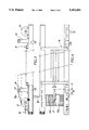
- FIGS. 1 and 2 are schematic cross-sectional and plan views of the cutting machine as a whole;
- FIGS. 3 and 4 are larger scale cross-sectional and plan views of the supporting chassis for the conveyor belts
- FIG. 5 is a view along line V--V of FIG. 4;
- FIG. 6 is an enlarged elevation view of the end of the cutting area.
- the machine shown in FIGS. 1 and 2 essentially comprises a feed table 1, an area 2 for cutting open bags of plasma and a collection area 3.
- the feed table is advantageously composed of two shaking tables 4 mounted on a bearing chassis 5, inside which are housed the motors 6 for driving the table.
- Each table is clearly designed to displace the bags that it receives in the direction of the cutting area.
- deflectors 7 orient the deep frozen bags 8 of plasma so that they arrive one after another in distribution chutes 9, longitudinally with regard to their direction of movement.
- a feed flap 12 capable of releasing the bags regularly in the direction of the following area.
- the bags 8 that leave chutes 9 are taken up by conveyor belts 10 which extend over the entire length of cutting area 2 opposite each distribution chute.
- Each conveyor belt which will be described in greater detail a little later, penetrates a sort of tunnel formed by a longitudinal hood 11 covering a substantial portion of the belt.
- the conveyor belt supplies collection area 3 with bags of plasma cut open, which are collected in a receptacle or seized by a mechanism, for the purpose of separating the bags from the plasma.
- FIGS. 3 and 4 show the support chassis 16 of a conveyor belt 10, while FIG. 5 is a cross-sectional view of an end of the chassis.
- Belt 10 is, in reality, composed of two longitudinal half belts, 10a and 10b, which are separated by a small gap d centered in the middle of chassis 16 and which travel side by side at the same speed. This gap is located vertically in relation to the cutting nozzle 13 so that the water projected can pass between the two half belts. The latter travel back over one and the same horizontal roller 17 mounted on each end of the chassis, one of them being capable of longitudinal movement, when subjected to the action of an appropriate mechanism 18, to adjust the tension of the belts. In the vicinity of the rollers, on each of the side members 25 of frame 16, are provided vertical brackets 19.
- Each bracket 19 serves to cantilever support an idler roller 20 which extends transversely of the chassis over a length substantially equal to the width of a half belt 10.
- each idler roller serves as a guide for a corresponding belt.
- the support bearing 21 of idler roller 20 is located at the top of the bracket and the idler roller is downwardly inclined in the direction of central gap d.
- its lower face is provided with a longitudinal rib 22 which cooperates with a groove 23 provided on the idler roller.
- belts 10a, 10b are compelled by idler rollers 20 to form in relation to one another a very open V shaped profile, the tip of the V being centered on gap d, this being the case over the entire length of the chassis.
- the two V forming belts are supported by a fixed sliding plane 24 the upper face of which is inclined in the same way. It will thus be appreciated that the bags of plasma that drop onto belt 10 are automatically centered above gap d, straddling the said gap and resting on the two half belts 10a and 10b.
- FIG. 6 gives a more detailed view of the end of cutting area 2 and table 26 which serves to support chassis 16, as well as the motor 27 used to drive a roller 17 via notched belts 28 and idle gears 29.
- each bag is cut open perfectly in the longitudinal direction into two equal portions, without any loss of product and without any fragments being torn off. As to the cut half bags, these are received by the collection area and are separated from the plasma manually or automatically. Protective hood 11 obviates any risk of accident to the user, and at the same time restricts any projection of water into the surrounding area.
- the frames and chassis serving to support the tables and cutting mechanisms also receive the electric cables supplying the different motors and the controls of the machine.
- the protective hoods 11, as well as the central guide of the distribution manifold, are equipped with position sensors so that, if they are removed at an untimely moment, the machine is shut down and the pressurized water supply is turned off. This water supply is ensured by a circuit external to the machine, the water being appropriate for the intended use and supplied from a tank.
Abstract
Description
Claims (4)
Applications Claiming Priority (2)
| Application Number | Priority Date | Filing Date | Title |
|---|---|---|---|
| FR9115077 | 1991-12-05 | ||
| FR9115077A FR2684587B1 (en) | 1991-12-05 | 1991-12-05 | CONTINUOUS CUTTING MACHINE OF PLASMA POCKETS. |
Publications (1)
| Publication Number | Publication Date |
|---|---|
| US5361661A true US5361661A (en) | 1994-11-08 |
Family
ID=9419705
Family Applications (1)
| Application Number | Title | Priority Date | Filing Date |
|---|---|---|---|
| US07/984,117 Expired - Lifetime US5361661A (en) | 1991-12-05 | 1992-12-04 | Machine for continuously cutting open bags of plasma |
Country Status (12)
| Country | Link |
|---|---|
| US (1) | US5361661A (en) |
| EP (1) | EP0545818B1 (en) |
| JP (1) | JP3390839B2 (en) |
| AT (1) | ATE140179T1 (en) |
| AU (1) | AU662572B2 (en) |
| BR (1) | BR9204839A (en) |
| DE (1) | DE69212122T2 (en) |
| DK (1) | DK0545818T3 (en) |
| FI (1) | FI102359B (en) |
| FR (1) | FR2684587B1 (en) |
| RU (1) | RU2128023C1 (en) |
| UA (1) | UA34425C2 (en) |
Cited By (8)
| Publication number | Priority date | Publication date | Assignee | Title |
|---|---|---|---|---|
| FR2814978A1 (en) * | 2000-10-10 | 2002-04-12 | Capelle | Vegetable top and root separator, especially for endives, has two parallel conveyor belts with guide and liquid jet cutter between |
| CN102275176A (en) * | 2011-08-05 | 2011-12-14 | 青岛双星橡塑机械有限公司 | Full-automatic rubber cutting machine |
| CN103071655A (en) * | 2013-01-16 | 2013-05-01 | 衡阳鑫山机械设备制造有限公司 | Combined equipment for automatically cleaning, disinfecting and breaking blood plasma bag |
| US20130333539A1 (en) * | 2011-03-09 | 2013-12-19 | Teseo S.P.A. | Machine for cutting leathers |
| CN112722468A (en) * | 2020-12-28 | 2021-04-30 | 吴光德 | Sterilization device on conveyor belt of fish frozen food packaging equipment |
| CN114933078A (en) * | 2022-06-16 | 2022-08-23 | 南华大学 | Tube cutting-bag breaking-ice discharging method for frozen plasma bag |
| CN114940295A (en) * | 2022-06-16 | 2022-08-26 | 南华大学 | Parallel air-blowing type plasma bag breaking method |
| CN114987873A (en) * | 2022-06-16 | 2022-09-02 | 南华大学 | Tube cutting-bag breaking-ice discharging assembly for frozen plasma bag |
Families Citing this family (6)
| Publication number | Priority date | Publication date | Assignee | Title |
|---|---|---|---|---|
| DE19901091C2 (en) * | 1999-01-14 | 2003-09-25 | Reika Werk Gmbh Maschf | Belt roller table for transporting rod-shaped workpieces |
| DE102009056225B4 (en) | 2009-11-28 | 2015-02-05 | Magurit Gefrierschneider Gmbh | Apparatus for the continuous opening and emptying of bags containing frozen goods, in particular blood plasma bags |
| JP6310241B2 (en) * | 2013-11-28 | 2018-04-11 | 環テックス株式会社 | Opening the bag containing the items to be stored |
| CN103753647B (en) * | 2014-01-20 | 2015-12-02 | 粤和兴激光刀模(深圳)有限公司 | The Water Cutting system that a kind of linear electric motors drive |
| CN103802154B (en) * | 2014-01-22 | 2015-08-12 | 安徽蓝德集团股份有限公司 | A kind of disc cutter both sides self adaptation hold down gag |
| CN106043864B (en) * | 2016-07-27 | 2018-03-02 | 华兰生物工程重庆有限公司 | Plasma bags clean broken bag conveyer |
Citations (10)
| Publication number | Priority date | Publication date | Assignee | Title |
|---|---|---|---|---|
| US2735466A (en) * | 1956-02-21 | Krstinich | ||
| US3631908A (en) * | 1970-05-28 | 1972-01-04 | Morris Meltzer | Automatic meat-cutting machine |
| DE2252451A1 (en) * | 1972-10-26 | 1974-05-16 | Reika Werk Gmbh Maschf | CONVEYOR DEVICE WITH GUTTER-SHAPED CONVEYOR TRACK |
| US3858473A (en) * | 1972-07-20 | 1975-01-07 | Schubert & Salzer Maschinen | Fabric control mechanism for textile cutting device |
| GB1534296A (en) * | 1976-05-25 | 1978-11-29 | Danepack Ltd | Bacon cutting apparatus |
| FR2531923A1 (en) * | 1982-08-06 | 1984-02-24 | Fichtel & Sachs Ag | BICYCLE DRIVE MECHANISM HAVING A RETROPEDAL BRAKE HUB AND BICYCLE COMPRISING SUCH A MECHANISM |
| US4457194A (en) * | 1981-09-28 | 1984-07-03 | Oscar Mayer Foods Corporation | Slicing method and apparatus |
| US4506572A (en) * | 1980-12-05 | 1985-03-26 | W. Schlafhorst & Co. | Bobbin separating unit |
| EP0170369A1 (en) * | 1984-07-27 | 1986-02-05 | Sortex Limited | Method and apparatus for controlling the cutting of an object |
| US5031496A (en) * | 1990-05-16 | 1991-07-16 | General Mills, Inc. | Apparatus and method utilizing a water jet for cutting frozen fish slabs into a plurality of individual portions |
Family Cites Families (1)
| Publication number | Priority date | Publication date | Assignee | Title |
|---|---|---|---|---|
| FR2531934A1 (en) * | 1982-08-20 | 1984-02-24 | Tricot Robert | Conveyor belt |
-
1991
- 1991-12-05 FR FR9115077A patent/FR2684587B1/en not_active Expired - Lifetime
-
1992
- 1992-12-03 AT AT92403261T patent/ATE140179T1/en active
- 1992-12-03 DE DE69212122T patent/DE69212122T2/en not_active Expired - Lifetime
- 1992-12-03 DK DK92403261.8T patent/DK0545818T3/en active
- 1992-12-03 EP EP92403261A patent/EP0545818B1/en not_active Expired - Lifetime
- 1992-12-04 BR BR9204839A patent/BR9204839A/en not_active IP Right Cessation
- 1992-12-04 US US07/984,117 patent/US5361661A/en not_active Expired - Lifetime
- 1992-12-04 RU RU92004498A patent/RU2128023C1/en not_active IP Right Cessation
- 1992-12-04 FI FI925527A patent/FI102359B/en not_active IP Right Cessation
- 1992-12-04 AU AU29912/92A patent/AU662572B2/en not_active Ceased
- 1992-12-04 JP JP35014492A patent/JP3390839B2/en not_active Expired - Fee Related
-
1993
- 1993-03-10 UA UA93002817A patent/UA34425C2/en unknown
Patent Citations (10)
| Publication number | Priority date | Publication date | Assignee | Title |
|---|---|---|---|---|
| US2735466A (en) * | 1956-02-21 | Krstinich | ||
| US3631908A (en) * | 1970-05-28 | 1972-01-04 | Morris Meltzer | Automatic meat-cutting machine |
| US3858473A (en) * | 1972-07-20 | 1975-01-07 | Schubert & Salzer Maschinen | Fabric control mechanism for textile cutting device |
| DE2252451A1 (en) * | 1972-10-26 | 1974-05-16 | Reika Werk Gmbh Maschf | CONVEYOR DEVICE WITH GUTTER-SHAPED CONVEYOR TRACK |
| GB1534296A (en) * | 1976-05-25 | 1978-11-29 | Danepack Ltd | Bacon cutting apparatus |
| US4506572A (en) * | 1980-12-05 | 1985-03-26 | W. Schlafhorst & Co. | Bobbin separating unit |
| US4457194A (en) * | 1981-09-28 | 1984-07-03 | Oscar Mayer Foods Corporation | Slicing method and apparatus |
| FR2531923A1 (en) * | 1982-08-06 | 1984-02-24 | Fichtel & Sachs Ag | BICYCLE DRIVE MECHANISM HAVING A RETROPEDAL BRAKE HUB AND BICYCLE COMPRISING SUCH A MECHANISM |
| EP0170369A1 (en) * | 1984-07-27 | 1986-02-05 | Sortex Limited | Method and apparatus for controlling the cutting of an object |
| US5031496A (en) * | 1990-05-16 | 1991-07-16 | General Mills, Inc. | Apparatus and method utilizing a water jet for cutting frozen fish slabs into a plurality of individual portions |
Cited By (13)
| Publication number | Priority date | Publication date | Assignee | Title |
|---|---|---|---|---|
| FR2814978A1 (en) * | 2000-10-10 | 2002-04-12 | Capelle | Vegetable top and root separator, especially for endives, has two parallel conveyor belts with guide and liquid jet cutter between |
| EP1197307A1 (en) * | 2000-10-10 | 2002-04-17 | Capelle | Cutting device with product guiding means, in particular for cutting chicory |
| US20130333539A1 (en) * | 2011-03-09 | 2013-12-19 | Teseo S.P.A. | Machine for cutting leathers |
| CN102275176A (en) * | 2011-08-05 | 2011-12-14 | 青岛双星橡塑机械有限公司 | Full-automatic rubber cutting machine |
| CN102275176B (en) * | 2011-08-05 | 2012-12-26 | 青岛双星橡塑机械有限公司 | Full-automatic rubber cutting machine |
| CN103071655A (en) * | 2013-01-16 | 2013-05-01 | 衡阳鑫山机械设备制造有限公司 | Combined equipment for automatically cleaning, disinfecting and breaking blood plasma bag |
| CN112722468A (en) * | 2020-12-28 | 2021-04-30 | 吴光德 | Sterilization device on conveyor belt of fish frozen food packaging equipment |
| CN114933078A (en) * | 2022-06-16 | 2022-08-23 | 南华大学 | Tube cutting-bag breaking-ice discharging method for frozen plasma bag |
| CN114940295A (en) * | 2022-06-16 | 2022-08-26 | 南华大学 | Parallel air-blowing type plasma bag breaking method |
| CN114987873A (en) * | 2022-06-16 | 2022-09-02 | 南华大学 | Tube cutting-bag breaking-ice discharging assembly for frozen plasma bag |
| CN114987873B (en) * | 2022-06-16 | 2023-05-16 | 南华大学 | Tube shearing-bag breaking-ice discharging assembly for frozen plasma bag |
| CN114933078B (en) * | 2022-06-16 | 2023-12-29 | 南华大学 | Method for cutting tube, breaking bag and discharging ice of frozen plasma bag |
| CN114940295B (en) * | 2022-06-16 | 2023-12-29 | 南华大学 | Parallel air-blowing type plasma bag breaking method |
Also Published As
| Publication number | Publication date |
|---|---|
| JPH05254526A (en) | 1993-10-05 |
| JP3390839B2 (en) | 2003-03-31 |
| AU2991292A (en) | 1993-06-10 |
| FR2684587B1 (en) | 1995-08-04 |
| FI102359B1 (en) | 1998-11-30 |
| FI925527A0 (en) | 1992-12-04 |
| AU662572B2 (en) | 1995-09-07 |
| EP0545818B1 (en) | 1996-07-10 |
| FR2684587A1 (en) | 1993-06-11 |
| ATE140179T1 (en) | 1996-07-15 |
| FI925527A (en) | 1993-06-06 |
| RU2128023C1 (en) | 1999-03-27 |
| BR9204839A (en) | 1993-06-08 |
| FI102359B (en) | 1998-11-30 |
| UA34425C2 (en) | 2001-03-15 |
| DE69212122T2 (en) | 1997-01-23 |
| EP0545818A1 (en) | 1993-06-09 |
| DE69212122D1 (en) | 1996-08-14 |
| DK0545818T3 (en) | 1996-11-18 |
Similar Documents
| Publication | Publication Date | Title |
|---|---|---|
| US5361661A (en) | Machine for continuously cutting open bags of plasma | |
| US7972088B2 (en) | Conveyor for a preparation machine used to orient objects | |
| US4962568A (en) | Method and apparatus for automatically cutting food products to predetermined weight or shape | |
| US5916354A (en) | Vegetable topping, tailing and cutting machine | |
| US5242324A (en) | Apparatus for processing gizzards of poultry | |
| US20080314716A1 (en) | Finishing Machines Used to Orient Objects | |
| GB2209771A (en) | Bale opener | |
| CA1213442A (en) | Method and apparatus for harvesting mushrooms and the like | |
| US6244144B1 (en) | Horizontal band saw device having multiple lanes of travel and associated method | |
| US4934682A (en) | Apparatus for feeding cartons | |
| KR101838697B1 (en) | Cabbage harvest apparatus with root cutting position adjestment function | |
| US5725717A (en) | Application of rows of labels to a packaging film | |
| ES2015795A6 (en) | Apparatus for guiding a textile web during trimming of selvedge therefrom | |
| US3631908A (en) | Automatic meat-cutting machine | |
| JPH0515299A (en) | Method and device for splitting butchered poultry into front and rear halves of body thereof | |
| US4214345A (en) | Machine for severing poultry into predetermined portions | |
| EP1511602B1 (en) | Device for eliminating end trimmings from a roll or the like | |
| US3515149A (en) | Apparatus for smoothing and destalking tobacco leaves | |
| CN216360191U (en) | Single-piece separator | |
| CN210256392U (en) | Feed arrangement of medicine cutting machine | |
| JP2849789B2 (en) | Root crop harvester | |
| US2724350A (en) | Macaroni cutting machine | |
| US3481378A (en) | Cutting apparatus | |
| US1338729A (en) | Sorting apparatus | |
| US964881A (en) | Machine for cutting fish, &c. |
Legal Events
| Date | Code | Title | Description |
|---|---|---|---|
| AS | Assignment |
Owner name: ASSOCIATION POUR L'ESSOR DE LA TRANSFUSION SANGUIN Free format text: ASSIGNMENT OF ASSIGNORS INTEREST.;ASSIGNORS:FAUCOMPRE, ANNICK;GIGOUT, JEAN-PIERRE;MAILLARD, JACQUES;AND OTHERS;REEL/FRAME:006456/0395;SIGNING DATES FROM 19921127 TO 19930104 |
|
| STCF | Information on status: patent grant |
Free format text: PATENTED CASE |
|
| FEPP | Fee payment procedure |
Free format text: PAYOR NUMBER ASSIGNED (ORIGINAL EVENT CODE: ASPN); ENTITY STATUS OF PATENT OWNER: LARGE ENTITY |
|
| CC | Certificate of correction | ||
| FEPP | Fee payment procedure |
Free format text: PAYOR NUMBER ASSIGNED (ORIGINAL EVENT CODE: ASPN); ENTITY STATUS OF PATENT OWNER: LARGE ENTITY Free format text: PAYER NUMBER DE-ASSIGNED (ORIGINAL EVENT CODE: RMPN); ENTITY STATUS OF PATENT OWNER: LARGE ENTITY |
|
| FPAY | Fee payment |
Year of fee payment: 4 |
|
| FPAY | Fee payment |
Year of fee payment: 8 |
|
| REMI | Maintenance fee reminder mailed | ||
| FPAY | Fee payment |
Year of fee payment: 12 |
|
| AS | Assignment |
Owner name: ETABLISSEMENT FRANCAIS DU SANG, FRANCE Free format text: ASSIGNMENT OF ASSIGNORS INTEREST;ASSIGNOR:ASSOCIATION POUR L'ESSOR DE LA TRANSFUSION SANGUINE DANS LA REGION DU NORD;REEL/FRAME:024982/0753 Effective date: 20071120 |