US5330366A - Connector with unlocking member - Google Patents
Connector with unlocking member Download PDFInfo
- Publication number
- US5330366A US5330366A US08/101,710 US10171093A US5330366A US 5330366 A US5330366 A US 5330366A US 10171093 A US10171093 A US 10171093A US 5330366 A US5330366 A US 5330366A
- Authority
- US
- United States
- Prior art keywords
- connector housing
- female connector
- unlocking member
- male connector
- male
- Prior art date
- Legal status (The legal status is an assumption and is not a legal conclusion. Google has not performed a legal analysis and makes no representation as to the accuracy of the status listed.)
- Expired - Fee Related
Links
Images


Classifications
-
- H—ELECTRICITY
- H01—ELECTRIC ELEMENTS
- H01R—ELECTRICALLY-CONDUCTIVE CONNECTIONS; STRUCTURAL ASSOCIATIONS OF A PLURALITY OF MUTUALLY-INSULATED ELECTRICAL CONNECTING ELEMENTS; COUPLING DEVICES; CURRENT COLLECTORS
- H01R13/00—Details of coupling devices of the kinds covered by groups H01R12/70 or H01R24/00 - H01R33/00
- H01R13/62—Means for facilitating engagement or disengagement of coupling parts or for holding them in engagement
- H01R13/627—Snap or like fastening
- H01R13/6271—Latching means integral with the housing
-
- H—ELECTRICITY
- H01—ELECTRIC ELEMENTS
- H01R—ELECTRICALLY-CONDUCTIVE CONNECTIONS; STRUCTURAL ASSOCIATIONS OF A PLURALITY OF MUTUALLY-INSULATED ELECTRICAL CONNECTING ELEMENTS; COUPLING DEVICES; CURRENT COLLECTORS
- H01R13/00—Details of coupling devices of the kinds covered by groups H01R12/70 or H01R24/00 - H01R33/00
- H01R13/62—Means for facilitating engagement or disengagement of coupling parts or for holding them in engagement
- H01R13/629—Additional means for facilitating engagement or disengagement of coupling parts, e.g. aligning or guiding means, levers, gas pressure electrical locking indicators, manufacturing tolerances
- H01R13/633—Additional means for facilitating engagement or disengagement of coupling parts, e.g. aligning or guiding means, levers, gas pressure electrical locking indicators, manufacturing tolerances for disengagement only
Definitions
- the present invention relates to a connector suitable for use to connect wire harness of an automotive vehicle, and more specifically to a connector provided with an unlocking member for unlocking a locked connector composed of male and female connector housings.
- FIGS. 1 and 2 show an example of a conventional connector provided with a lock and unlock mechanism, which is disclosed in Japanese Patent Laid Open (Kokai) No. 62-22381.
- the connector is composed of a male connector housing a and a female connector housing d.
- the male connector housing a is formed with a flexible locking arm b and an arch-shaped lock guard portion c.
- the flexible locking arm b is further formed with a locking projection b 1 and an arch-shaped unlocking portion b 2 .
- the female connector housing d is formed with a lock pawl portion e.
- the arch-shaped lock guard portion c serves to prevent the locked conditions of both the locking projection b1 and the lock pawl portion e from being released inadvertently by an unexpected force.
- a connector provided with an unlocking member comprises: a female connector housing (A, A') formed with a locking pawl portion (5, 5'); a male connector housing (B, B') formed with a flexible locking arm (12, 12') having a locking projection (14, 14') engaged with the locking pawl portion of said female connector housing; and an unlocking member (C, C') formed with an unlock drive projection (10, 10') and a male connector removal portion (8, 8'), said unlocking member being so arranged that, when moved within said female connector housing, said unlocking member deforming the flexible locking arm (12, 12') of said male connector housing by bringing the unlock drive projection (10, 10') thereof into contact with the locking projection (14, 14') of said male connector housing to disengage the locking projection (14, 14') of said male connector housing from the locking pawl portion (5, 5') of said female connector housing and further removing said male connector housing from said female connector housing by the male connector removal portion (8
- the male connector housing (B) is further formed with at least one unlock driven projection (13), when moved within said female connector housing, said unlocking member deforming the flexible locking arm (12) of said male connector housing by bringing the unlock drive projection (10) thereof into contact with the unlock driven projection (13) of said male connector housing to disengage the locking projection (14) of said male connector housing from the locking pawl portion (5) of said female connector housing.
- the locking member (C) is pulled out of said female connector housing to remove said male connector housing from said female connector housing, or else the locking member (C') is pushed into said female connector housing to remove said male connector housing from said female connector housing.
- the locking projection of the male connector housing can be disengaged from the locking pawl portion of the female connector housing, and further the male connector housing can be removed from the female connector housing by the male connector removal portion of the unlocking member.
- FIG. 1 is a perspective view showing a male connector housing of an example of a conventional connector provided with a lock and unlock mechanism;
- FIG. 2 is a cross-section view showing the same conventional connector shown in FIG. 1, in which the male and female connector housings are engaged with each other under locked condition;
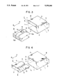
- FIG. 3 is a perspective view showing a first embodiment of the connector provided with an unlocking member, in which a male connector housing is disengaged from a female connector housing;
- FIG. 4 is a perspective view showing the first embodiment of the connector provided with an unlocking member, in which an unlocking member is removed from the female connector housing;
- FIG. 5 is a perspective view showing a reverse side of the unlocking member
- FIG. 6 is a cross-sectional view showing the female connector housing to which the unlocking member is inserted
- FIG. 7 is a cross-sectional view showing the connector shown in FIG. 3, in which the male connector housing is engaged with the female connector housing under locked condition;
- FIG. 8 is a cross-sectional view showing the connector shown in FIG. 3, in which the unlocking member is slightly pulled out of the female connector housing to unlock the male connector housing from the female connector housing;
- FIG. 9 is a cross-sectional view showing the connector shown in FIG. 3, in which the unlocking member is sufficiently pulled out of the female connector housing and thereby the male connector housing is unlocked from the female connector housing;
- FIG. 10 is a cross-sectional view showing the connector shown in FIG. 3, in which the unlocking member is sufficiently pulled out of the female connector housing and thereby the male connector housing can be removed from the female connector housing;
- FIG. 11 is a cross-sectional view showing a second embodiment of the connector provided with an unlocking member, in which a male connector housing is engaged with a female connector housing under locked condition.
- the connector is composed of a female connector housing A, a male connector housing B and an unlocking member C,as shown in FIG. 3. Further, the unlocking member C is removably engaged with the female connector housing A, as shown in FIG. 4.
- the female connector housing A is formed with two side walls 1 and upper and lower walls 4.
- two opposing unlocking member guide portions 2 are formed extending in the front and rear (R-F) or the longitudinal direction of the connector.
- two opposing side slits 3 are formed in the two side walls 1 also extending in the front and rear direction.
- a lockingpawl portion 5 extending downward is formed on the rear side and at the middle portion of the upper wall 4.
- the unlocking member C is formed with an unlocking memberpull-out portion 7 bent vertically upward at the rearmost end of a plate portion 6 and a male connector removal portion 8 bent vertically downward at the front end of the pate portion 6. Further, the unlocking member C isformed with a longitudinal slit 9 loosely engaged with the downward extending locking pawl portion 5 of the female connector housing A, a pairof angular unlock drive projections 10 (see FIG. 5) each having two opposing sloped surfaces 10a extending in the front and rear direction andlocated on the inner surface of the plate portion 6 and on both sides of the slit 9, and a pair of horizontal triangular projections 11 extending in the transversal direction of the connector housing.
- the unlocking member C can be engaged with the female connector housing A as follows: First, the front end of the plate portion 6 is fitted to the unlocking member guide portions 2; the unlocking member C isfurther pushed into the female connector housing A until the horizontal triangular projections 11 are engaged with the two side slits 3. Under these engage conditions, the downward extending locking pawl portion 5 is located in the longitudinal slit 9 formed in the plate portion 6 of the unlocking member C, and further the unlocking member C is movably engaged with the female connector housing A with the two horizontal traingular projections 11 engaged with the two side slits 3 of the female connector housing A.
- the male connector housing B is formed with a flexible locking arm 12 of fixed beam type on the upper surface thereof so as to extend in the front and rear direction.
- the flexible locking arm 12 is formed with a pair of angular unlock driven projections 13 each having a sloped guide surface 13a (see FIG. 7) on the front side and a locking projection 14 having a sloped surface 14a (see FIG. 7) also on the front side, respectively.
- FIG. 6 shows the state where the unlocking member C is inserted into and further engaged with the female connector housing A.
- the unlocking member C is movable in the female connector housing between the solid line position and the dot-dot-dashed line position, because the two horizontal triangular projections 11 of the unlocking member C are slidable along the two side slits 3 of the female connector housing A.
- FIG. 11 shows a second embodiment of the connector provided with an unlocking member according to the present invention.
- the male and female connector housings A and B can be removed by pulling the unlocking member C from the female connector housing (A) side to the male connector housing (B) side.
- the male connector housing can be removed from thefemale connector housing by pushing the unlocking member from the female connector housing side to the male connector housing side.
- the two unlock driven projections 13 of the male connector housing B is omitted.
- an unlocking member C' is engaged with a female connector housing A', and a male connector housing B' is engaged with the female connector housing A'.
- An unlocking member push-in portion 7' projects fromthe front side of the female connector housing A'.
- the unlocking member C' is formed with anunlock drive projection 10'.
- the male connector housing B' is formed with aflexible locking arm 12' of fixed beam type. Further, the flexible locking arm 12' is formed with a locking projection 14'. However, no unlock drivenprojections are formed in the male connector housing B'.
- the male connector housing can be removed from the female connector housing, by simply pulling out or pushing in the unlocking member in the longitudinal direction of the connector, without providing any guard portion, it is possible to easily release the locking condition of the male and female connector housings, while improving the connection reliability of the two connector housings.
Landscapes
- Details Of Connecting Devices For Male And Female Coupling (AREA)
Abstract
A connector provided with an unlocking member comprises: a female connector housing formed with a locking pawl portion; a male connector housing formed with a flexible locking arm having a locking projection engaged with the locking pawl portion of the female connector housing; an unlocking member formed with an unlock drive projection and a male connector removal portion. When moved within the female connector housing, the unlocking member deforms the flexible locking arm by bringing the unlock drive projection thereof into contact with the locking projection to disengage the locking projection from the locking pawl portion and further removes the male connector housing from the female connector housing by the male connector removal portion thereof. In the connector, since the locking condition of both male and female connector housings can be released simply by pulling-out or pushing-in the unlocking member, it is possible to facilitate connector unlocking work within a narrow space.
Description
The present invention relates to a connector suitable for use to connect wire harness of an automotive vehicle, and more specifically to a connector provided with an unlocking member for unlocking a locked connector composed of male and female connector housings.
FIGS. 1 and 2 show an example of a conventional connector provided with a lock and unlock mechanism, which is disclosed in Japanese Patent Laid Open (Kokai) No. 62-22381.
In these drawings, the connector is composed of a male connector housing a and a female connector housing d. The male connector housing a is formed with a flexible locking arm b and an arch-shaped lock guard portion c. The flexible locking arm b is further formed with a locking projection b1 and an arch-shaped unlocking portion b2. On the other hand, the female connector housing d is formed with a lock pawl portion e.
Therefore, when the male connector housing a is inserted into the female connector housing d as shown in FIG. 2, since the locking projection b1 is engaged with the lock pawl portion e, the two male and female connector housings a and d are locked to each other. On the other hand, when the arch-shaped unlocking portion b2 is pushed down, since the locking projection b1 is disengaged from the lock pawl portion e, the two male and female connector housings a and d are unlocked from each other. Here, the arch-shaped lock guard portion c serves to prevent the locked conditions of both the locking projection b1 and the lock pawl portion e from being released inadvertently by an unexpected force.
In the conventional connector provided with the lock and unlock mechanism as described above, however, when the connector is required to be unlocked within a narrow or limited space within an automotive vehicle, since the arch-shaped lock guard portion c is present, there exists a problem in that it is not easy to unlock the connector by the worker's fingers. In other words, it has been difficult to push the unlocking portion b2 from above in the transversal direction of the connector housings within a narrow and small space, for removal of the male connector housing a form the female connector housing d.
With these problems in mind, therefore, it is the primary object of the present invention to provide a connector provided with an unlocking member, by which the male connector housing can be easily removed from the female connector housing even within a narrow space or a limited space, by simply pulling out or pushing in an unlocking member along the longitudinal direction of the connector housings.
To achieve the above-mentioned object, the present invention provide a connector provided with an unlocking member comprises: a female connector housing (A, A') formed with a locking pawl portion (5, 5'); a male connector housing (B, B') formed with a flexible locking arm (12, 12') having a locking projection (14, 14') engaged with the locking pawl portion of said female connector housing; and an unlocking member (C, C') formed with an unlock drive projection (10, 10') and a male connector removal portion (8, 8'), said unlocking member being so arranged that, when moved within said female connector housing, said unlocking member deforming the flexible locking arm (12, 12') of said male connector housing by bringing the unlock drive projection (10, 10') thereof into contact with the locking projection (14, 14') of said male connector housing to disengage the locking projection (14, 14') of said male connector housing from the locking pawl portion (5, 5') of said female connector housing and further removing said male connector housing from said female connector housing by the male connector removal portion (8, 8') thereof.
Further, the male connector housing (B) is further formed with at least one unlock driven projection (13), when moved within said female connector housing, said unlocking member deforming the flexible locking arm (12) of said male connector housing by bringing the unlock drive projection (10) thereof into contact with the unlock driven projection (13) of said male connector housing to disengage the locking projection (14) of said male connector housing from the locking pawl portion (5) of said female connector housing.
The locking member (C) is pulled out of said female connector housing to remove said male connector housing from said female connector housing, or else the locking member (C') is pushed into said female connector housing to remove said male connector housing from said female connector housing.
In the connector provided with an unlocking member according to the present invention, when the unlocking member is pulled out of or pushed into the female connector housing, since the flexible locking arm of the male connector housing is deformed by bringing the unlock drive projection of the unlocking member into contact with the locking projection or the unlock driven projection of the male connector housing, the locking projection of the male connector housing can be disengaged from the locking pawl portion of the female connector housing, and further the male connector housing can be removed from the female connector housing by the male connector removal portion of the unlocking member.
FIG. 1 is a perspective view showing a male connector housing of an example of a conventional connector provided with a lock and unlock mechanism;
FIG. 2 is a cross-section view showing the same conventional connector shown in FIG. 1, in which the male and female connector housings are engaged with each other under locked condition;
FIG. 3 is a perspective view showing a first embodiment of the connector provided with an unlocking member, in which a male connector housing is disengaged from a female connector housing;
FIG. 4 is a perspective view showing the first embodiment of the connector provided with an unlocking member, in which an unlocking member is removed from the female connector housing;
FIG. 5 is a perspective view showing a reverse side of the unlocking member;
FIG. 6 is a cross-sectional view showing the female connector housing to which the unlocking member is inserted;
FIG. 7 is a cross-sectional view showing the connector shown in FIG. 3, in which the male connector housing is engaged with the female connector housing under locked condition;
FIG. 8 is a cross-sectional view showing the connector shown in FIG. 3, in which the unlocking member is slightly pulled out of the female connector housing to unlock the male connector housing from the female connector housing;
FIG. 9 is a cross-sectional view showing the connector shown in FIG. 3, in which the unlocking member is sufficiently pulled out of the female connector housing and thereby the male connector housing is unlocked from the female connector housing;
FIG. 10 is a cross-sectional view showing the connector shown in FIG. 3, in which the unlocking member is sufficiently pulled out of the female connector housing and thereby the male connector housing can be removed from the female connector housing; and
FIG. 11 is a cross-sectional view showing a second embodiment of the connector provided with an unlocking member, in which a male connector housing is engaged with a female connector housing under locked condition.
A first embodiment of the connector provided with an unlocking member according to the present invention will be described hereinbelow with reference to FIGS. 3 to 10. The connector is composed of a female connector housing A, a male connector housing B and an unlocking member C,as shown in FIG. 3. Further, the unlocking member C is removably engaged with the female connector housing A, as shown in FIG. 4.
In FIG. 4, the female connector housing A is formed with two side walls 1 and upper and lower walls 4. Under the upper wall 4, two opposing unlocking member guide portions 2 are formed extending in the front and rear (R-F) or the longitudinal direction of the connector. Further, under the upper wall 4, two opposing side slits 3 are formed in the two side walls 1 also extending in the front and rear direction. Further, a lockingpawl portion 5 extending downward is formed on the rear side and at the middle portion of the upper wall 4.
In FIGS. 4 and 5, the unlocking member C is formed with an unlocking memberpull-out portion 7 bent vertically upward at the rearmost end of a plate portion 6 and a male connector removal portion 8 bent vertically downward at the front end of the pate portion 6. Further, the unlocking member C isformed with a longitudinal slit 9 loosely engaged with the downward extending locking pawl portion 5 of the female connector housing A, a pairof angular unlock drive projections 10 (see FIG. 5) each having two opposing sloped surfaces 10a extending in the front and rear direction andlocated on the inner surface of the plate portion 6 and on both sides of the slit 9, and a pair of horizontal triangular projections 11 extending in the transversal direction of the connector housing.
Therefore, the unlocking member C can be engaged with the female connector housing A as follows: First, the front end of the plate portion 6 is fitted to the unlocking member guide portions 2; the unlocking member C isfurther pushed into the female connector housing A until the horizontal triangular projections 11 are engaged with the two side slits 3. Under these engage conditions, the downward extending locking pawl portion 5 is located in the longitudinal slit 9 formed in the plate portion 6 of the unlocking member C, and further the unlocking member C is movably engaged with the female connector housing A with the two horizontal traingular projections 11 engaged with the two side slits 3 of the female connector housing A.
As shown in FIG. 3, the male connector housing B is formed with a flexible locking arm 12 of fixed beam type on the upper surface thereof so as to extend in the front and rear direction. The flexible locking arm 12 is formed with a pair of angular unlock driven projections 13 each having a sloped guide surface 13a (see FIG. 7) on the front side and a locking projection 14 having a sloped surface 14a (see FIG. 7) also on the front side, respectively.
The locking and unlocking operation of the connector provided with the unlocking member C according to the present invention will be described hereinbelow with reference to FIGS. 6 to 11.
FIG. 6 shows the state where the unlocking member C is inserted into and further engaged with the female connector housing A. In these conditions, the unlocking member C is movable in the female connector housing between the solid line position and the dot-dot-dashed line position, because the two horizontal triangular projections 11 of the unlocking member C are slidable along the two side slits 3 of the female connector housing A.
Under these conditions, when the male connector housing B is inserted into the female connector housing A, since the sloped surface 14a of the locking projection 14 is brought into contact with the lock pawl portion 5, the flexible locking arm 12 is deformed in the inward direction of the male connector housing B, so that the locking projection 14 can be moved over the lock pawl portion 5. After that, the flexible locking arm 12 is restored into the locked condition in which a vertical locking surface 14b(see FIG. 7) is engaged with the locking pawl portion 5, as shown in FIG. 7. Under these engaged conditions, a pair of connector terminals (not shown) provided in the male and female connector housings A and B can be connected to each other.
As shown in FIG. 8, when the unlocking member C is extracted for unlocking operation by moving the unlocking member pull-out portion 7 of the unlocking member C in the rear direction of the connector, since the unlock drive projections 10 of the unlocking member C pushes the unlock driven projections 13 inward, the flexible locking arm 12 is deformed, so that the locking projection 14 is disengaged from the locking pawl portion5. Under these conditions, since the male connector removal portion 8 of the unlocking member C is in contact with a front end surface 12a (see FIG. 7) of the male connector housing B, when the unlocking member pull-out portion 7 is further pulled out, since the locking projection 14 of the male connector housing B is perfectly disengaged from the locking pawl portion 5 of the female connector housing A as shown in FIG. 9, the male connector housing B can be removed from the female connector housing A, as shown in FIG. 10.
FIG. 11 shows a second embodiment of the connector provided with an unlocking member according to the present invention. In the first embodiment, the male and female connector housings A and B can be removed by pulling the unlocking member C from the female connector housing (A) side to the male connector housing (B) side. In contrast with this, in this second embodiment, the male connector housing can be removed from thefemale connector housing by pushing the unlocking member from the female connector housing side to the male connector housing side. Further, in this second embodiment, the two unlock driven projections 13 of the male connector housing B is omitted.
In more detail, an unlocking member C' is engaged with a female connector housing A', and a male connector housing B' is engaged with the female connector housing A'. An unlocking member push-in portion 7' projects fromthe front side of the female connector housing A'. In the same way, as withthe case of the first embodiment, the unlocking member C' is formed with anunlock drive projection 10'. The male connector housing B' is formed with aflexible locking arm 12' of fixed beam type. Further, the flexible locking arm 12' is formed with a locking projection 14'. However, no unlock drivenprojections are formed in the male connector housing B'.
In FIG. 11, when the unlocking member C' is pushed toward the male connector housing B', since the unlock drive projections 10' of the unlocking member C' push the locking projections 14' of the male connectorhousing B', the flexible locking arm 12' of the male connector housing B' is deformed inward, so that the male connector housing B' can be moved by the male connector removal portion 8' of the unlocking member C'. When thelocking projections 14' are moved into contact with the lower surface of the locking pawl portion 5', since the two connector housings A' and B' can be unlocked, the male connector housing B' can be further removed fromthe female connector housing A' freely.
As described above, in the connector provided with an unlocking member according to the present invention, since the male connector housing can be removed from the female connector housing, by simply pulling out or pushing in the unlocking member in the longitudinal direction of the connector, without providing any guard portion, it is possible to easily release the locking condition of the male and female connector housings, while improving the connection reliability of the two connector housings.
Claims (6)
1. A connector provided with an unlocking member, comprising:
a female connector housing having an opening provided at an end thereof, being formed with a locking pawl portion projecting from a wall of said female connector housing and extending in an inward direction;
a male connector housing for being fitted into the opening of said female connector housing, being formed with a flexible locking arm extending in a fitting direction and being supported by a wall of said male connector housing at both ends thereof and having a locking projection engagable with the locking pawl portion of said female connector housing; and
an unlocking member held by said female connector housing so as to be slidable in a direction opposite to the fitting direction during disengagement of the male connector housing from the female housing, being formed with an unlock drive projection and a male connector removal portion, said unlocking member being so arranged that, when moved within said female connector housing, said unlocking member deforms the flexible locking arm of said male connector housing by bringing the unlock drive projection thereof into contact with the locking projection of said male connector housing to disengage the locking projection of said male connector housing from the locking pawl portion of said female connector housing and further removing said male connector housing from said female connector housing by urging said male connector housing past the male connector removal portion thereof.
2. The connector provided with an unlocking member of claim 1, wherein said unlocking member is pulled out of said female connector housing to remove said male connector housing from said female connector housing.
3. The connector provided with an unlocking member of claim 1, wherein said unlocking member is pushed into said female connector housing to remove said male connector housing from said female connector housing.
4. A connector provided with an unlocking member comprising:
a female connector housing having an opening at an end thereof, being formed with a locking pawl portion projecting from a wall of said female connector toward an inside thereof;
a male connector housing for being fitted into the opening of said female connector, being integrally formed with a flexible locking arm extending in a fitting direction and supported by a wall of said male connector housing at both ends thereof, said flexible locking arm having a locking projection engaged with the locking pawl portion of said female connector housing and at least one unlock driven projection projecting from said flexible locking arm; and
an unlocking member held by said female connector so as to be slidable in a direction opposite to the fitting direction during disengagement of the male connector housing from the female connector housing, being formed with at least one unlock drive projection and a male connector removal portion, said unlocking member being so arranged that, when moved within said female connector housing, said unlocking member deforms the flexible locking arm of said male connector housing by bringing the unlock drive projection thereof into contact with the unlock driven projection of said male connector housing to disengage the locking projection of said male connector housing from the locking pawl portion of said female connector housing and further removing said male connector housing from said female connector housing by pushing said male connector by the male connector removal portion thereof.
5. The connector as claimed in claim 4, wherein said unlocking member is pulled out of said female connector housing to remove said male connector housing from said female connector housing.
6. The connector as claimed in claim 4, wherein said unlocking member is pushed into said female connector housing to remove said male connector housing from said female connector housing.
Applications Claiming Priority (2)
| Application Number | Priority Date | Filing Date | Title |
|---|---|---|---|
| JP1992054683U JP2570376Y2 (en) | 1992-08-04 | 1992-08-04 | Connector locking device |
| JP4-054683[U] | 1992-08-04 |
Publications (1)
| Publication Number | Publication Date |
|---|---|
| US5330366A true US5330366A (en) | 1994-07-19 |
Family
ID=12977595
Family Applications (1)
| Application Number | Title | Priority Date | Filing Date |
|---|---|---|---|
| US08/101,710 Expired - Fee Related US5330366A (en) | 1992-08-04 | 1993-08-04 | Connector with unlocking member |
Country Status (2)
| Country | Link |
|---|---|
| US (1) | US5330366A (en) |
| JP (1) | JP2570376Y2 (en) |
Cited By (44)
| Publication number | Priority date | Publication date | Assignee | Title |
|---|---|---|---|---|
| US5496190A (en) * | 1993-09-10 | 1996-03-05 | Connecteurs Cinch | Electrical connector casings |
| US5562475A (en) * | 1995-02-02 | 1996-10-08 | Aines Manufacturing Corp. | Modular telephone plug |
| US5662488A (en) * | 1996-10-31 | 1997-09-02 | Alden; Peter H. | Quick connect coupling system for rapidly joining connectors and/or other elongated bodies |
| EP0757411A3 (en) * | 1995-08-03 | 1997-10-15 | Sumitomo Wiring Systems | Connector |
| US5759058A (en) * | 1995-06-06 | 1998-06-02 | Cardell Corporation | Connector position assurance component |
| US5993237A (en) * | 1999-04-12 | 1999-11-30 | Aines Manufacturing Corp. | Modular telephone plug |
| US6004153A (en) * | 1996-03-27 | 1999-12-21 | The Whitaker Corporation | Electrical connector with connector position assurance device |
| EP0895317A3 (en) * | 1997-07-29 | 2000-05-24 | Hirose Electric Co., Ltd. | Lock lever release for connector |
| US6083042A (en) * | 1997-05-09 | 2000-07-04 | Yazaki Corporation | Adjustable connecting device |
| US6123575A (en) * | 1999-07-30 | 2000-09-26 | Huang; Wayne | Electrical card connector with mixed latching means |
| US6203353B1 (en) * | 1999-11-12 | 2001-03-20 | Hon Hai Precision Ind. Co., Ltd. | Electrical connector with passive clip |
| EP1093192A1 (en) * | 1999-10-14 | 2001-04-18 | Framatome Connectors International | Detachable connector |
| US6273763B1 (en) * | 2000-02-29 | 2001-08-14 | Avaya Technology Corp. | Connector assembly and disassembly device |
| US6554646B1 (en) | 1998-12-14 | 2003-04-29 | Berg Electronics Group, Inc. | Electrical connector assembly |
| US6592390B1 (en) | 2002-04-30 | 2003-07-15 | Tyco Electronics Corporation | HMZD cable connector latch assembly |
| FR2842034A1 (en) * | 2002-07-06 | 2004-01-09 | Amphenol Tuchel Elect | ELECTRICAL PLUG CONNECTOR |
| US20040166716A1 (en) * | 2003-02-21 | 2004-08-26 | Alcatel | Device for hooking/unhooking LC connectors |
| US20050184264A1 (en) * | 2004-02-23 | 2005-08-25 | Christopher Tesluk | Fluid conduit connector apparatus |
| US7027596B1 (en) * | 1999-11-16 | 2006-04-11 | Mitel Networks Corporation | Apparatus for releasing teledapt cables from deeply recessed RJ connectors |
| US20060089039A1 (en) * | 2004-10-22 | 2006-04-27 | Caveney Jack E | Push-pull plugs and tools |
| US20080077063A1 (en) * | 2006-09-21 | 2008-03-27 | Tyco Healthcare Group Lp | Safety Connector Apparatus |
| US7473124B1 (en) | 2008-02-29 | 2009-01-06 | Tyco Electronics Corporation | Electrical plug assembly with bi-directional push-pull actuator |
| WO2009007025A3 (en) * | 2007-07-06 | 2009-04-09 | Tyco Electronics Amp Gmbh | Plug-in connector |
| US7534125B1 (en) * | 2008-02-26 | 2009-05-19 | Tyco Electronics Corporation | Electrical connector having a multi-directional latching mechanism |
| US20090149052A1 (en) * | 2007-12-05 | 2009-06-11 | Yazaki Corporation | Connector |
| US20090176400A1 (en) * | 2008-01-04 | 2009-07-09 | Wayne Samuel Davis | Cable connector assembly |
| US20090240178A1 (en) * | 2008-03-20 | 2009-09-24 | Tyco Healthcare Group Lp | Safety connector assembly |
| US7871387B2 (en) | 2004-02-23 | 2011-01-18 | Tyco Healthcare Group Lp | Compression sleeve convertible in length |
| CN102195206A (en) * | 2010-03-03 | 2011-09-21 | Wago管理有限责任公司 | Plug connector device with unlocking device |
| CN103378449A (en) * | 2012-04-27 | 2013-10-30 | 日本航空电子工业株式会社 | Connector |
| US20140322955A1 (en) * | 2013-04-30 | 2014-10-30 | Cheng Uei Precision Industry Co., Ltd. | Cable connector |
| US20150037997A1 (en) * | 2013-08-02 | 2015-02-05 | GM Global Technology Operations LLC | Multiple-stage interlocking electrical connector with locking assurance mechanism |
| US20150077149A1 (en) * | 2012-09-04 | 2015-03-19 | Phoenix Contact Gmbh & Co. Kg | Test terminal block |
| EP2997628A1 (en) * | 2013-05-15 | 2016-03-23 | Neutrik Ag | Plug part |
| US20160156128A1 (en) * | 2014-11-27 | 2016-06-02 | Yazaki Corporation | Connector and connection structure of connector |
| EP2852857A4 (en) * | 2012-05-22 | 2016-06-29 | Adc Telecommunications Inc | Ruggedized fiber optic connector |
| US20160248190A1 (en) * | 2015-02-25 | 2016-08-25 | Molex, Llc | Connector assembly |
| US9609763B2 (en) | 2009-07-28 | 2017-03-28 | Koninklijke Philips N.V. | Housing with locking structure |
| CN107851934A (en) * | 2015-08-07 | 2018-03-27 | 株式会社自动网络技术研究所 | Electrical connection arrangement with chimeric detection function |
| US20190237904A1 (en) * | 2018-01-30 | 2019-08-01 | Wago Verwaltungsgesellschaft Mbh | Electrical plug connection |
| US10978830B2 (en) * | 2017-11-27 | 2021-04-13 | HARTING Electronics GmbH | Lockable and releasable plug |
| US20210408727A1 (en) * | 2020-06-28 | 2021-12-30 | Amphenol Commercial Products (Chengdu) Co., Ltd. | Electrical connector and method for mating and unmating the same |
| US11276958B2 (en) * | 2019-03-25 | 2022-03-15 | Molex, Llc | Connector |
| WO2022093217A1 (en) * | 2020-10-28 | 2022-05-05 | Hewlett-Packard Development Company, L.P. | Receptacles with sliders to release connectors |
Citations (6)
| Publication number | Priority date | Publication date | Assignee | Title |
|---|---|---|---|---|
| US4526431A (en) * | 1983-02-14 | 1985-07-02 | Nec Corporation | Connector with mechanism for coupling and uncoupling plurality of blocks |
| US4582378A (en) * | 1983-02-09 | 1986-04-15 | Amp Incorporated | Electrical connector assembly and an ejector bar therefor |
| JPS6222381A (en) * | 1985-07-22 | 1987-01-30 | 日産自動車株式会社 | Connector with lock mechanism |
| US4940430A (en) * | 1988-02-01 | 1990-07-10 | Sumitomo Wiring Systems, Ltd. | Electrical connector with openable cover |
| US4993967A (en) * | 1989-07-03 | 1991-02-19 | Yazaki Corporation | Electric connector with a double locking mechanism |
| US5154630A (en) * | 1990-12-28 | 1992-10-13 | Amp Incorporated | Plug connector assembly |
-
1992
- 1992-08-04 JP JP1992054683U patent/JP2570376Y2/en not_active Expired - Fee Related
-
1993
- 1993-08-04 US US08/101,710 patent/US5330366A/en not_active Expired - Fee Related
Patent Citations (6)
| Publication number | Priority date | Publication date | Assignee | Title |
|---|---|---|---|---|
| US4582378A (en) * | 1983-02-09 | 1986-04-15 | Amp Incorporated | Electrical connector assembly and an ejector bar therefor |
| US4526431A (en) * | 1983-02-14 | 1985-07-02 | Nec Corporation | Connector with mechanism for coupling and uncoupling plurality of blocks |
| JPS6222381A (en) * | 1985-07-22 | 1987-01-30 | 日産自動車株式会社 | Connector with lock mechanism |
| US4940430A (en) * | 1988-02-01 | 1990-07-10 | Sumitomo Wiring Systems, Ltd. | Electrical connector with openable cover |
| US4993967A (en) * | 1989-07-03 | 1991-02-19 | Yazaki Corporation | Electric connector with a double locking mechanism |
| US5154630A (en) * | 1990-12-28 | 1992-10-13 | Amp Incorporated | Plug connector assembly |
Cited By (80)
| Publication number | Priority date | Publication date | Assignee | Title |
|---|---|---|---|---|
| US5496190A (en) * | 1993-09-10 | 1996-03-05 | Connecteurs Cinch | Electrical connector casings |
| US5562475A (en) * | 1995-02-02 | 1996-10-08 | Aines Manufacturing Corp. | Modular telephone plug |
| US5893771A (en) * | 1995-02-02 | 1999-04-13 | Aines Manufacturing Corp. | Modular telephone plug |
| US5759058A (en) * | 1995-06-06 | 1998-06-02 | Cardell Corporation | Connector position assurance component |
| EP0757411A3 (en) * | 1995-08-03 | 1997-10-15 | Sumitomo Wiring Systems | Connector |
| US6004153A (en) * | 1996-03-27 | 1999-12-21 | The Whitaker Corporation | Electrical connector with connector position assurance device |
| US5662488A (en) * | 1996-10-31 | 1997-09-02 | Alden; Peter H. | Quick connect coupling system for rapidly joining connectors and/or other elongated bodies |
| US6733339B2 (en) * | 1997-03-07 | 2004-05-11 | Berg Technology, Inc. | Shielded connector with integral latching and ground structure |
| US6083042A (en) * | 1997-05-09 | 2000-07-04 | Yazaki Corporation | Adjustable connecting device |
| EP0895317A3 (en) * | 1997-07-29 | 2000-05-24 | Hirose Electric Co., Ltd. | Lock lever release for connector |
| US6554646B1 (en) | 1998-12-14 | 2003-04-29 | Berg Electronics Group, Inc. | Electrical connector assembly |
| US5993237A (en) * | 1999-04-12 | 1999-11-30 | Aines Manufacturing Corp. | Modular telephone plug |
| US6123575A (en) * | 1999-07-30 | 2000-09-26 | Huang; Wayne | Electrical card connector with mixed latching means |
| FR2799889A1 (en) * | 1999-10-14 | 2001-04-20 | Fci France | REMOVABLE CONNECTOR |
| US6379173B1 (en) | 1999-10-14 | 2002-04-30 | Framatome Connectors International | Detachable connector |
| EP1093192A1 (en) * | 1999-10-14 | 2001-04-18 | Framatome Connectors International | Detachable connector |
| US6203353B1 (en) * | 1999-11-12 | 2001-03-20 | Hon Hai Precision Ind. Co., Ltd. | Electrical connector with passive clip |
| US7027596B1 (en) * | 1999-11-16 | 2006-04-11 | Mitel Networks Corporation | Apparatus for releasing teledapt cables from deeply recessed RJ connectors |
| US6273763B1 (en) * | 2000-02-29 | 2001-08-14 | Avaya Technology Corp. | Connector assembly and disassembly device |
| US6592390B1 (en) | 2002-04-30 | 2003-07-15 | Tyco Electronics Corporation | HMZD cable connector latch assembly |
| FR2842034A1 (en) * | 2002-07-06 | 2004-01-09 | Amphenol Tuchel Elect | ELECTRICAL PLUG CONNECTOR |
| US20040166716A1 (en) * | 2003-02-21 | 2004-08-26 | Alcatel | Device for hooking/unhooking LC connectors |
| US7004779B2 (en) * | 2003-02-21 | 2006-02-28 | Alcatel | Device for hooking/unhooking LC connectors |
| US8256459B2 (en) | 2004-02-23 | 2012-09-04 | Tyco Healthcare Group Lp | Fluid conduit connector apparatus |
| US20090146092A1 (en) * | 2004-02-23 | 2009-06-11 | Tyco Healthcare Group Lp | Fluid conduit connector apparatus |
| US7810519B2 (en) | 2004-02-23 | 2010-10-12 | Tyco Healthcare Group Lp | Fluid conduit connector apparatus |
| US7490620B2 (en) | 2004-02-23 | 2009-02-17 | Tyco Healthcare Group Lp | Fluid conduit connector apparatus |
| US20100276619A1 (en) * | 2004-02-23 | 2010-11-04 | Tyco Healthcare Group Lp | Fluid conduit connector apparatus |
| US7871387B2 (en) | 2004-02-23 | 2011-01-18 | Tyco Healthcare Group Lp | Compression sleeve convertible in length |
| US20050184264A1 (en) * | 2004-02-23 | 2005-08-25 | Christopher Tesluk | Fluid conduit connector apparatus |
| US7297013B2 (en) * | 2004-10-22 | 2007-11-20 | Panduit Corp. | Push-pull plugs and tools |
| US20080057770A1 (en) * | 2004-10-22 | 2008-03-06 | Panduit Corp. | Push-Pull Plugs and Tools |
| US20060089039A1 (en) * | 2004-10-22 | 2006-04-27 | Caveney Jack E | Push-pull plugs and tools |
| US7534128B2 (en) | 2004-10-22 | 2009-05-19 | Panduit Corp. | Push-pull plugs and tools |
| US20080077063A1 (en) * | 2006-09-21 | 2008-03-27 | Tyco Healthcare Group Lp | Safety Connector Apparatus |
| US8257286B2 (en) | 2006-09-21 | 2012-09-04 | Tyco Healthcare Group Lp | Safety connector apparatus |
| US8287517B2 (en) | 2006-09-21 | 2012-10-16 | Tyco Healtcare Group Lp | Safety connector assembly |
| US9687249B2 (en) | 2006-09-21 | 2017-06-27 | Covidien Lp | Safety connector assembly |
| US7824207B2 (en) | 2007-07-06 | 2010-11-02 | Tyco Electronics Amp Gmbh | Plug-in connector with a sleeve with an unlocking member |
| US20100173513A1 (en) * | 2007-07-06 | 2010-07-08 | Bert Bergner | Plug-In Connector |
| WO2009007025A3 (en) * | 2007-07-06 | 2009-04-09 | Tyco Electronics Amp Gmbh | Plug-in connector |
| CN101689730B (en) * | 2007-07-06 | 2012-09-05 | 泰科电子Amp有限责任公司 | Plug-in connector |
| US7785128B2 (en) * | 2007-12-05 | 2010-08-31 | Yazaki Corporation | Connector |
| US20090149052A1 (en) * | 2007-12-05 | 2009-06-11 | Yazaki Corporation | Connector |
| US7637767B2 (en) | 2008-01-04 | 2009-12-29 | Tyco Electronics Corporation | Cable connector assembly |
| US20090176400A1 (en) * | 2008-01-04 | 2009-07-09 | Wayne Samuel Davis | Cable connector assembly |
| US7534125B1 (en) * | 2008-02-26 | 2009-05-19 | Tyco Electronics Corporation | Electrical connector having a multi-directional latching mechanism |
| US7473124B1 (en) | 2008-02-29 | 2009-01-06 | Tyco Electronics Corporation | Electrical plug assembly with bi-directional push-pull actuator |
| US20090240178A1 (en) * | 2008-03-20 | 2009-09-24 | Tyco Healthcare Group Lp | Safety connector assembly |
| US8257287B2 (en) | 2008-03-20 | 2012-09-04 | Tyco Healthcare Group Lp | Safety connector assembly |
| US9609763B2 (en) | 2009-07-28 | 2017-03-28 | Koninklijke Philips N.V. | Housing with locking structure |
| CN102195206A (en) * | 2010-03-03 | 2011-09-21 | Wago管理有限责任公司 | Plug connector device with unlocking device |
| CN102195206B (en) * | 2010-03-03 | 2015-03-25 | Wago管理有限责任公司 | Plug connector device with unlocking device |
| CN103378449B (en) * | 2012-04-27 | 2015-09-09 | 日本航空电子工业株式会社 | Connector |
| CN103378449A (en) * | 2012-04-27 | 2013-10-30 | 日本航空电子工业株式会社 | Connector |
| US20130288512A1 (en) * | 2012-04-27 | 2013-10-31 | Japan Aviation Electronics Industry, Limited | Connector |
| US8876543B2 (en) * | 2012-04-27 | 2014-11-04 | Japan Aviation Electronics Industry, Limited | Connector |
| US9684138B2 (en) | 2012-05-22 | 2017-06-20 | Commscope Technologies Llc | Ruggedized fiber optic connector |
| EP2852857A4 (en) * | 2012-05-22 | 2016-06-29 | Adc Telecommunications Inc | Ruggedized fiber optic connector |
| US9476909B2 (en) * | 2012-09-04 | 2016-10-25 | Phoenix Contact Gmbh & Co. Kg | Test terminal block |
| US20150077149A1 (en) * | 2012-09-04 | 2015-03-19 | Phoenix Contact Gmbh & Co. Kg | Test terminal block |
| US8882527B1 (en) * | 2013-04-30 | 2014-11-11 | Cheng Uei Precision Industry Co., Ltd. | Cable connector |
| US20140322955A1 (en) * | 2013-04-30 | 2014-10-30 | Cheng Uei Precision Industry Co., Ltd. | Cable connector |
| EP2997628A1 (en) * | 2013-05-15 | 2016-03-23 | Neutrik Ag | Plug part |
| US9048576B2 (en) * | 2013-08-02 | 2015-06-02 | GM Global Technology Operations LLC | Multiple-stage interlocking electrical connector with locking assurance mechanism |
| US20150037997A1 (en) * | 2013-08-02 | 2015-02-05 | GM Global Technology Operations LLC | Multiple-stage interlocking electrical connector with locking assurance mechanism |
| US20160156128A1 (en) * | 2014-11-27 | 2016-06-02 | Yazaki Corporation | Connector and connection structure of connector |
| US9590354B2 (en) * | 2014-11-27 | 2017-03-07 | Yazaki Corporation | Connector and connection structure of connector |
| US20160248190A1 (en) * | 2015-02-25 | 2016-08-25 | Molex, Llc | Connector assembly |
| US9583872B2 (en) * | 2015-02-25 | 2017-02-28 | Molex, Llc | Connector assembly having an elastic engaging portion |
| CN107851934A (en) * | 2015-08-07 | 2018-03-27 | 株式会社自动网络技术研究所 | Electrical connection arrangement with chimeric detection function |
| CN107851934B (en) * | 2015-08-07 | 2019-08-16 | 株式会社自动网络技术研究所 | Electrical connection device with mating detection function |
| US10978830B2 (en) * | 2017-11-27 | 2021-04-13 | HARTING Electronics GmbH | Lockable and releasable plug |
| US20190237904A1 (en) * | 2018-01-30 | 2019-08-01 | Wago Verwaltungsgesellschaft Mbh | Electrical plug connection |
| US10608377B2 (en) * | 2018-01-30 | 2020-03-31 | Wago Verwaltungsgesellschaft Mbh | Electrical plug connection |
| US11276958B2 (en) * | 2019-03-25 | 2022-03-15 | Molex, Llc | Connector |
| US20210408727A1 (en) * | 2020-06-28 | 2021-12-30 | Amphenol Commercial Products (Chengdu) Co., Ltd. | Electrical connector and method for mating and unmating the same |
| US11777256B2 (en) * | 2020-06-28 | 2023-10-03 | Amphenol Commercial Products (Chengdu) Co., Ltd. | Electrical connector and method for mating and unmating the same |
| TWI907449B (en) * | 2020-06-28 | 2025-12-11 | 大陸商安費諾商用電子產品(成都)有限公司 | Electrical connector and method for mating and unmating the same |
| WO2022093217A1 (en) * | 2020-10-28 | 2022-05-05 | Hewlett-Packard Development Company, L.P. | Receptacles with sliders to release connectors |
Also Published As
| Publication number | Publication date |
|---|---|
| JPH0617146U (en) | 1994-03-04 |
| JP2570376Y2 (en) | 1998-05-06 |
Similar Documents
| Publication | Publication Date | Title |
|---|---|---|
| US5330366A (en) | Connector with unlocking member | |
| US5234356A (en) | Connector | |
| JP3467202B2 (en) | Connector locking mechanism | |
| JP3362014B2 (en) | Lock and unlock structure of cable connector and method of locking and unlocking | |
| JP4405164B2 (en) | Electrical connector assembly and electrical connector half assembly | |
| US5391090A (en) | Locking mechanism for connectors | |
| US11342708B2 (en) | Set of connectors having a locking device | |
| EP1005111A2 (en) | Connector | |
| JP2964880B2 (en) | connector | |
| EP0554827A2 (en) | Connector capable of automatically and reliably inhibiting disengagement of mechanical coupling between connection members | |
| US5033980A (en) | Electrical connector with a double locking structure for terminals | |
| EP1085617B1 (en) | A connector | |
| EP1233480B1 (en) | A connector and a method of assembling a connector | |
| JP2651395B2 (en) | connector | |
| JPH0716374U (en) | Double lock type connector | |
| EP0940883B1 (en) | Connector retaining construction | |
| US20020016106A1 (en) | Connector and a method for detaching housings thereof | |
| US6413118B2 (en) | Connector housing and a connector | |
| JP3945342B2 (en) | connector | |
| JP2546579Y2 (en) | connector | |
| EP0484951B1 (en) | Connector locking connection detection device | |
| US6027378A (en) | Combined-type connector | |
| JPH06223921A (en) | connector | |
| JP2000195610A (en) | Connector | |
| US5219459A (en) | Latch connector |
Legal Events
| Date | Code | Title | Description |
|---|---|---|---|
| AS | Assignment |
Owner name: YAZAKI CORPORATION, JAPAN Free format text: ASSIGNMENT OF ASSIGNORS INTEREST;ASSIGNORS:TSUJI, MASANORI;KASHIYAMA, MOTOHISA;REEL/FRAME:006649/0189 Effective date: 19930702 |
|
| FPAY | Fee payment |
Year of fee payment: 4 |
|
| FPAY | Fee payment |
Year of fee payment: 8 |
|
| REMI | Maintenance fee reminder mailed | ||
| LAPS | Lapse for failure to pay maintenance fees | ||
| STCH | Information on status: patent discontinuation |
Free format text: PATENT EXPIRED DUE TO NONPAYMENT OF MAINTENANCE FEES UNDER 37 CFR 1.362 |
|
| FP | Lapsed due to failure to pay maintenance fee |
Effective date: 20060719 |