EP1233480B1 - A connector and a method of assembling a connector - Google Patents
A connector and a method of assembling a connector Download PDFInfo
- Publication number
- EP1233480B1 EP1233480B1 EP01123222A EP01123222A EP1233480B1 EP 1233480 B1 EP1233480 B1 EP 1233480B1 EP 01123222 A EP01123222 A EP 01123222A EP 01123222 A EP01123222 A EP 01123222A EP 1233480 B1 EP1233480 B1 EP 1233480B1
- Authority
- EP
- European Patent Office
- Prior art keywords
- connector
- slider
- engaging portion
- housings
- resiliently
- Prior art date
- Legal status (The legal status is an assumption and is not a legal conclusion. Google has not performed a legal analysis and makes no representation as to the accuracy of the status listed.)
- Expired - Lifetime
Links
Images


Classifications
-
- H—ELECTRICITY
- H01—ELECTRIC ELEMENTS
- H01R—ELECTRICALLY-CONDUCTIVE CONNECTIONS; STRUCTURAL ASSOCIATIONS OF A PLURALITY OF MUTUALLY-INSULATED ELECTRICAL CONNECTING ELEMENTS; COUPLING DEVICES; CURRENT COLLECTORS
- H01R13/00—Details of coupling devices of the kinds covered by groups H01R12/70 or H01R24/00 - H01R33/00
- H01R13/64—Means for preventing incorrect coupling
- H01R13/641—Means for preventing incorrect coupling by indicating incorrect coupling; by indicating correct or full engagement
-
- H—ELECTRICITY
- H01—ELECTRIC ELEMENTS
- H01R—ELECTRICALLY-CONDUCTIVE CONNECTIONS; STRUCTURAL ASSOCIATIONS OF A PLURALITY OF MUTUALLY-INSULATED ELECTRICAL CONNECTING ELEMENTS; COUPLING DEVICES; CURRENT COLLECTORS
- H01R13/00—Details of coupling devices of the kinds covered by groups H01R12/70 or H01R24/00 - H01R33/00
- H01R13/62—Means for facilitating engagement or disengagement of coupling parts or for holding them in engagement
- H01R13/627—Snap or like fastening
- H01R13/6271—Latching means integral with the housing
- H01R13/6272—Latching means integral with the housing comprising a single latching arm
-
- H—ELECTRICITY
- H01—ELECTRIC ELEMENTS
- H01R—ELECTRICALLY-CONDUCTIVE CONNECTIONS; STRUCTURAL ASSOCIATIONS OF A PLURALITY OF MUTUALLY-INSULATED ELECTRICAL CONNECTING ELEMENTS; COUPLING DEVICES; CURRENT COLLECTORS
- H01R13/00—Details of coupling devices of the kinds covered by groups H01R12/70 or H01R24/00 - H01R33/00
- H01R13/62—Means for facilitating engagement or disengagement of coupling parts or for holding them in engagement
- H01R13/629—Additional means for facilitating engagement or disengagement of coupling parts, e.g. aligning or guiding means, levers, gas pressure electrical locking indicators, manufacturing tolerances
- H01R13/633—Additional means for facilitating engagement or disengagement of coupling parts, e.g. aligning or guiding means, levers, gas pressure electrical locking indicators, manufacturing tolerances for disengagement only
- H01R13/635—Additional means for facilitating engagement or disengagement of coupling parts, e.g. aligning or guiding means, levers, gas pressure electrical locking indicators, manufacturing tolerances for disengagement only by mechanical pressure, e.g. spring force
Definitions
- the present invention relates to a connector provided with a connection detecting function and to an assembling method for such a connector.
- a connector disclosed in Japanese Unexamined Patent Publication No. 11-185880 is known as a connector of this type.
- This connector is constructed, as shown in FIG. 9, such that a lock arm 3 is provided on a female housing 1 to be connected with a male housing 2, a slider 4 is mounted in the male housing 2 and a coil spring 5 is provided at the rear wall of the male housing 2. While the housings 1, 2 are being connected with each other, the elastically deformed lock arm 3 pushes the slider 4 against a biasing force of the coil spring 5.
- the female housing 1 is pulled after unlocking is effected by forcibly elastically deforming the lock arm 3. If pulling of the female housing 1 is interrupted for a certain reason and left in such a state, the housings 1, 2 may be left partly connected during a separating operation.
- EP 0 841 724 A2 which is considered to represent the closest prior art, discloses a connector comprising a male and a female connector housings, wherein a movable member is movably provided in the male connector housing and biased by coils springs towards the female connector housing. Moreover, a lock arm is provided in the female connector housing, which pushes a receiving portion of the movable member upon connection of the connector housings. Since the receiving portion is inclined, the lock arm is deflected downward until the engagement with the receiving portion is cancelled. The lock arm is engageable with a lock hole provided in the movable member to lock the connector housings in their properly engaged states.
- a further connector is known from DE 197 14 459 A1 having a housing locking, which comprises a first locking element on one connector housing and a second locking element on the other connector housing.
- the first locking element comprises two locking arms being arranged parallel to the connection direction which comprise at their distal ends two locking hooks oriented outwardly.
- a receiver section is formed on the other connector housing and has a pair of parallel guides, wherein a sliding element with a load spring is positioned on the other connector housing. The locking hooks on the locking arms engage slots in the other connector housing to latch the two connector housings together.
- EP 0 583 056 A1 discloses an electrical connector which includes first and second connector housings for holding first and second terminals, respectively, a short-circuiting element accommodated in the first housing in electrical contact with two first terminals, a sliding element arranged on the second housing, and an urging element for urging the sliding element in a direction forward from the second housing.
- the first housing includes a pair of resiliently-deformable engaging arms each having an engaging protrusion.
- the second housing releasably fitted to the first housing, includes a pair of first guide grooves for receiving the engaging arms. Each first guide groove has an engaging portion with which the engaging protrusion is held in engagement and a stepped wall portion formed adjacent to the front end of the second housing.
- the sliding element has a front tongue engageable with the short-circuiting element to disengage the same from the two first terminals.
- the engaging arms and the first guide grooves are constructed so that upon fitting of the connector housings, the engaging arms are resiliently deformed in a lateral direction by the stepped wall portions to be brought into abutment with the sliding element to move the same towards the rear end of the second housing, whereas upon completion of the fitting, the engaging arms are restored to a released position where the engaging protrusions are held in engagement with the engaging portions of the first guide grooves, while permitting the sliding element to move in a direction forward from the second housing.
- a partial connection detection is enabled both during a connecting operation and during a separating operation.
- a connector having at least one pair of connector housings at least partly connectable with each other, comprising:
- the slider engaged with the resiliently engaging portion located in the first position can be moved backward both at an intermediate stage of an operation of connecting the connector housings and at an intermediate stage of an operation of separating the connector housings, and/or when the connector housings are substantially properly connected with each other, the resiliently engaging portion is not engageable with the slider along the connecting and separating directions by being resiliently displaced to the second position and the slider can be moved forward.
- the slider is assembled into the first connector housing via a biasing means, the slider engaged with the resiliently engaging portion located in the first position can be moved backward against a biasing force of the biasing means both at an intermediate stage of an operation of connecting the connector housings and at an intermediate stage of an operation of separating the connector housings, and when the connector housings are substantially properly connected with each other, the slider is moved forward by the release of the biasing force accumulated in the biasing means.
- a connector having a pair of connector housings connectable with each other, comprising:
- the slider is moved backward preferably against the biasing force of the slider by being pushed by the resiliently or elastically engaging portion located in the engaging position. If the connecting operation is interrupted at this stage, the biasing force preferably accumulated in the biasing means is released, whereby the slider biased forward pushes the elastically engaging portion to forcibly separate the connector housings. As a result, partial connection can be detected.
- the elastically engaging portion is disengaged from the slider to be released from a state pushed by the slider and the biasing force accumulated in the biasing means is released, with the result that the slider is moved forward.
- the connected connector housings are separated by moving the slider backward preferably against the biasing force of the biasing means. If the separating operation is interrupted halfway, the slider biased forward by the release of the biasing force accumulated in the biasing means comes into engagement with the elastically engaging portion elastically displaced from the disengaging position to the engaging position to forcibly separate the connector housings. As a result, partial connection can be detected.
- the resiliently or elastically engaging portion is or comprises a lock arm which is resiliently or elastically displaced from the second or disengaging position to the first or engaging position by moving onto the one connector housing at the intermediate stage of the connecting or separating operation of the connector housings, and is resiliently or elastically displaced from the first or engaging position to the second or disengaging position and is engaged with the first or one connector housing to (preferably inseparably) hold the connector housings locked into each other when the connector housings are substantially properly connected with each other.
- a lock arm which is resiliently or elastically displaced from the second or disengaging position to the first or engaging position by moving onto the one connector housing at the intermediate stage of the connecting or separating operation of the connector housings, and is resiliently or elastically displaced from the first or engaging position to the second or disengaging position and is engaged with the first or one connector housing to (preferably inseparably) hold the connector housings locked into each other when the connector housings are substantially properly connected with each other.
- the construction of the connector can be simplified by using the lock arm also as the elastically engaging portion.
- the resiliently or elastic engaging portion engages the slider in a direction at an angle different from 0° or 180°, preferably substantially normal to the connecting and separating directions so as to prevent the displacement of the resiliently or elastically engaging portion to unlock the housings from each other.
- the slider comprises an operable portion for moving the slider backward preferably against the biasing force of the biasing means, the operable portion being so formed as to project out from the connector.
- the slider can be easily moved back by operating the operable portion projecting out while the connector housings are being separated from each other.
- the slider is located in such a position as to restrict an elastic or resilient displacement of the resiliently or elastically engaging portion engaged with the first or one connector housing when the connector housings are substantially properly connected with each other.
- engaging portions of the resiliently or elastically engaging portion and the first or one connector housing engageable with each other are formed with guide surfaces capable of guiding an elastic or resilient displacement of the resiliently or elastically engaging portion from the second or disengaging position to the first or engaging position only when the connector housings are pulled in separating direction with a specified (predetermined or predeterminable) force or larger.
- the connector housings In order to separate the connector housings, they are pulled in separating directions with a specified force or larger after the slider is moved backward up to a position where the elastic displacement of the elastically engaging portion is permitted. Then, the elastically engaging portion is automatically elastically displaced to the disengaging position where it is disengaged from the one connector housing by being guided by the guide surfaces.
- the connector housings can be smoothly separated from each other.
- the slider is movable in a disconnecting direction of the first connector housing from the second connector housing to thereby allow a resilient displacement of the resiliently engaging portion to unlock the connector housings from each other.
- the resiliently engaging portion comprises a guiding portion for coming into contact with the slider so as to urge the resiliently engaging portion towards the second position.
- the resiliently engageable portion is provided in a receptacle of the second housing into which the first housing is at least partly fittable or insertable.
- a method of assembling or mating a connector preferably according to the invention or an embodiment thereof, having at least one pair of connector housings at least partly connectable with each other, comprising the following steps:
- the slider engaged with the resiliently engaging portion located in the first position is moved backward both at an intermediate stage of an operation of connecting the connector housings and at an intermediate stage of an operation of separating the connector housings, and/or when the connector housings are substantially properly connected with each other, the resiliently engaging portion is not engageable with the slider along the connecting and separating directions by being resiliently displaced to the second position and the slider is moved forward.
- a connector of this embodiment is comprised of a male connector housing 10 (hereinafter, merely “male housing 10”) and a female connector housing 30 (hereinafter, merely “female housing 30”), the male housing 10 being provided with a lock arm 18, and a slider 51 being mounted in the female housing 30 via compression coil springs 50.
- sides of the housings 10, 30 to be connected with each other are referred to as front.
- the male housing 10 is, as shown in FIGS. 1 and 3, provided with a receptacle 11 integrally or unitarily formed e.g. of a synthetic resin with a wall surface of an equipment and substantially in the form of a substantially rectangular tube projecting forward.
- the female housing 30 is at least partly fittable or insertable into the receptacle 11 from front.
- E.g. four male tab terminals 12 arranged preferably substantially side by side along widthwise direction project from a back wall of the male housing 10. These tab terminals 12 project into the receptacle 11 and are electrically connectable with female terminal fittings 31 of the female housing 30.
- a shorting terminal 13 is preferably accommodated in the back wall of the male housing 10 preferably below the male tab terminals 12.
- the shorting terminal 13 is preferably provided with a substantially plate-shaped main portion 14 and a corresponding number of, e.g. four elastic or resilient contact pieces 15 folded at the rear end of the main portion 15 to project substantially forward.
- the main portion 15 of the shorting terminal 13 is pressed or fitted into a mount groove 16 which substantially is in flush with the inner surface of the receptacle 11, and the respective elastic contact pieces 15 are at least partly accommodated in accommodating recesses 17 which are so formed as to face the respective male tab terminals 12, and are resiliently or elastically held in contact with the respective male tab terminals 12.
- the four male tab terminals 12 are shorted with each other so as to cause no potential difference among them.
- the respective elastic contact pieces 15 are arranged such that their front portions project into the receptacle 11 and their leading ends 15a are bent down, they are elastically or resiliently pushed down or away from the male tab terminals 12 to separate from the male tab terminals 12 by the female housing 30 fitted into the receptacle 11.
- the lock arm 18 in the form of a cantilever projects preferably substantially from a widthwise center position of the back wall of the male housing 10 above the male tab terminals 12 or on a side thereof opposing the shorting terminal 13.
- the lock arm 18 projects slightly more forward than the male tab terminals 12, and is elastically or resiliently deformable or displaceable about its base end along vertical direction in FIGURES or a displacement direction D which is a direction intersecting with a connecting and separating direction CSD or arranged at an angle different from 0° or 180°, preferably substantially normal to the connection direction.
- a hook portion 19 projecting down is formed at a free end (front end) of the lock arm 18.
- the fitted housings 10, 30 can be inseparably held locked into each other by engaging a rear end surface 20 of the hook portion 19 with a rear end surface 40 of a bulging portion 38 of the female housing 30 to be described later.
- a notch 21 for permitting entrance of an operable portion 55 of the slider 51 of the female housing 30 to be described later is formed in a corresponding position, preferably substantially in a widthwise center position of the upper wall of the receptacle 11.
- a length of this notch 21 is substantially equal to a moving stroke of the slider 51.
- the lock arm 18 is located behind the rear end surface of the notch 21 and is substantially completely laterally surrounded by the wall surfaces of the receptacle 11. Further, opposite side ends of the bottom of the receptacle 11 project downward and a pair of guide recesses 22 for receiving guide ribs 36 of the female housing 30 are formed therein.
- the female housing 30 is formed e.g. of a synthetic resin preferably into a substantially block shape, and cavities 32 for at least partly accommodating the female terminal fittings 31 connected or connectable with ends of wires W penetrate through the female housing 30 substantially in forward and backward or longitudinal directions.
- cavities 32 for at least partly accommodating the female terminal fittings 31 connected or connectable with ends of wires W penetrate through the female housing 30 substantially in forward and backward or longitudinal directions.
- four cavities 32 are formed substantially side by side in widthwise direction in positions in alignment with the mating male tab terminals 12.
- a retainer mount hole 33 crossing the respective cavities 32 is preferably formed in one side of the female housing 30, and a retainer 34 which projects or can project into the respective cavities 32 to directly lock the female terminal fittings 31 is mounted or mountable in this retainer mount hole 33.
- the pair of guide ribs 36 capable of guiding the connection of the housings 10, 30 by entering or fitting the guide recesses 22 of the male housing 10 project down at the opposite side ends of the bottom surface of the female housing 30.
- An operable rib 37 extending in widthwise direction projects down from the rear end of the bottom surface of the female housing 30.
- the female housing 30 is or can be connected with and separated from the male housing 10 by gripping this operable rib 37.
- the bulging portion 38 bulges up to the same height or radial position (height or radial position overlapping with the hook portion 19) as the lower surface of an arm portion of the lock arm 18 of the male housing 10.
- an escape groove or recess or notch 39 for permitting the entrance of the hook portion 19 of the lock arm 18 extends backward or away from the male connector housing 10.
- the locking surfaces 20, 40 (rear end surfaces) of the hook portion 19 and the bulging portion 38 are moderately sloped or rounded upward to the left in FIGURES, thereby forming a semi-locking construction or releasable locking construction.
- a specified (predetermined or predeterminable) force or larger as to separate the housings 10, 30 from each other acts with the hook portion 19 engaged with the bulging portion 38
- the lock arm 18 is automatically elastically or resiliently deformed or displaced upward while being freed from the locked state by being guided by the slanted or rounded guide surfaces of the locking surfaces 20, 40.
- a pair of side walls 41 project upward or laterally at the substantially opposite side ends of the upper surface of the female housing 30, a pair of ceiling walls 42 project toward each other from the upper ends of the side walls 41, and a rear wall 43 extending in widthwise direction is so provided at the rear end of the upper surface of the female housing 30 as to be connected with the side walls 41 and the ceiling walls 42. As shown in FIG.
- the slider 51 accommodating the compression coil springs 50 is assembled from front into a space above the female housing 30 surrounded by the side walls 41, the ceiling walls 42 and the rear wall 43, and is movable in forward and backward or longitudinal directions substantially along the connecting direction of the housings 10, 30 while being guided preferably by the upper surface of the female housing 30, the side edges of the bulging portion 38, the side walls 41 and the ceiling walls 42.
- the slider 51 is formed e.g. of a synthetic resin and is constructed such that spring accommodating portions 52 for at least partly accommodating a pair of compression coil springs 50 are formed at its opposite ends and are bridged or connected by a coupling portion 53 in the middle. As shown in FIG. 3B, rear parts of the spring accommodating portions 52 are so recessed as to at least partly accommodate the compression coil springs 50 while slightly compressing them along a longitudinal direction thereof between the rear surfaces of the spring accommodating portions 52 and the front end surface of the rear wall 43. By moving the slider 51 backward in this state, the compression coil springs 50 can be elastically or resiliently deformed while storing even larger spring forces (see FIG. 5(B)).
- a pair of stopper projections 54 project sideways from the opposite side surfaces of the slider 51 as shown in FIG.
- slider 51 is stopped at its limit position which is slightly retracted from the front end surface of the female housing 30 by introducing the stopper projections 54 into stopper grooves 44 formed in the side walls 41 and bringing them into engagement of the front end surfaces of the stopper grooves 44 whereby a range of movement of the slider 51 is limited by the stopper projections 54 and the stopper grooves 44 acting as preferred movement range limiting means.
- the coupling portion 53 of the slider 51 has a lower surface substantially at the same height or radial position as the upper surface of the lock arm 18 in its natural or undeflected or undeformed state as shown in FIG. 3(A). Accordingly, when the lock arm 18 is elastically or resiliently deformed or displaced to displace its free end upward or to radially displacing the free end thereof, the front end surface of the lock arm 18 is engageable with the front end surface of the coupling portion 53.
- the position of the lock arm 18 at this time is referred to as an engaging or first position (see FIG. 5(A)).
- the position of the lock arm 18 where it is in its natural state and cannot be engaged with the front end surface of the coupling portion 53 of the slider 51 is referred to as a disengaging or second position. Since the coupling portion 53 of the slider 51 is located above or radially outward the lock arm 18 preferably substantially over its entire length with the housings 10, 30 connected with each other, it can prevent the lock arm 18 engaged with the bulging portion 38 from being elastically deformed upward (see FIG. 6).
- the operable portion 55 pushed to forcibly move the slider 51 back against the biasing forces of the compression coil springs 50 projects up from the upper surface at the rear end of the coupling portion 53.
- the operable portion 55 has a height or radial extension set such that it projects out from the upper surface of the male housing 10 (outer contour of the connector) through the space between the ceiling walls 42 and the notch 21 of the male housing 10 with the housings 10, 30 connected with each other (see FIG. 6).
- the operable portion 55 is substantially held in sliding contact with the respective side edges of the ceiling walls 42 and the notch 21 while the slider 51 is moved forward and backward.
- the housings 10, 30 are connected with each other as follows. First, the female housing 30 is fitted into the receptacle 11 of the male housing 10 after the male and female housings 10, 30 substantially are faced or aligned with each other as shown in FIG. 3. Before the male tab terminals 12 enter the cavities 32 of the female housing 30, the lock arm 18 engages the front end surface of the bulging portion 38 to be elastically or resiliently deformed to the engaging or first position while moving onto the upper or lateral surface of the bulging portion 38. Thereafter, the front end surface of the lock arm 18 is engaged with the front end surface of the coupling portion 53 of the slider 51 located at the position slightly retracted from the front end surface of the bulging portion 38.
- the connecting operation may be interrupted halfway.
- the spring forces accumulated in the elastically compressed coil springs 50 are released, and the slider 51 biased forward pushes the lock arm 18 to forcibly separate the housings 10, 30 from each other. This prevents the housings 10, 30 from being kept partly connected.
- the engaging recesses 35 of the female housing 30 come into engagement with the respective elastic contact pieces 15 of the shorting terminal 13 to elastically deform them downward or away from the male tab terminal 12 so as to be disengaged from the male tab terminals 12.
- the shorted state of the respective male tab terminals 12 can be canceled (see FIG. 6).
- the slider 51 disengaged from the lock arm 18 is moved forward by the released spring forces accumulated in the compression coil springs 50, and is stopped at the same position as it was before the housings 10, 30 are connected by the movement range limiting means, preferably by the stopper projections 54 coming into contact with the front end surfaces of the stopper grooves 44.
- the coupling portion 53 of the slider 51 covering the lock arm 18 substantially over its entire length prevents the lock arm 18 located in the disengaging position from being elastically or resiliently deformed upward.
- the housings 10, 30 are firmly held locked into each other so as to be inseparable from each other since the lock arm 18 and the bulging portion 38 are engaged and the lock arm 18 is prevented from being elastically or resiliently deformed in unlocking direction by the slider 51. Accordingly, the radial engagement of the lock arm 18 with the slider 51 (or radial abutting of the lock arm 18 on the slider 51) prevents an unlocking of the connector housings 10, 20.
- the operable portion 55 of the slider 51 is located in the notch 21 of the receptacle 11 and its front end surface is held in contact with or in proximity to the front end surface of the notch 21.
- the slider 51 is moved backward while elastically compressing the coil springs 50 by pushing the operable portion 55 of the slider 51 projecting upward from the receptacle 11, and the female housing 30 is pulled in separating direction by gripping the operable rib 37 of the female housing 30.
- the lock arm 18 is automatically elastically or resiliently deformed upward or in a radial direction by a pulling force acting on the female housing 30 in separating direction while being guided by the slanted guide surfaces 20, 40 of the hook portion 19 and the bulging portion 38.
- the female housing 30 is moved away from the male housing 10
- the locking surfaces 20, 40 of the hook portion 19 and the bulging portion 38 are disengaged from each other as shown in FIG. 8 and the female housing 30 is pulled out in this state.
- the separating operation may also be interrupted halfway for a certain reason.
- the spring forces accumulated in the elastically compressed coil springs 50 are released, thereby moving the slider 51 forward and striking it against the front end surface of the lock arm 18 in the engaging position as indicated in phantom in FIG. 8.
- the housings 10, 30 are forcibly separated from each other.
- partial connection of the housings 10, 30 can be detected not only at the time of the connecting operation, but also at the time of the separating operation.
- the lock arm 18 is provided with a function of inseparably holding the housings 10, 30 locked into each other and a function of engaging the slider 51, the construction of the connector can be simplified as compared to a case where separate parts bear these two functions.
- the operable portion 55 for forcibly moving the slider 51 backward during the separating operation projects out from the outer contour of the connector, the separating operation can be easily performed.
Abstract
Description
- The present invention relates to a connector provided with a connection detecting function and to an assembling method for such a connector.
- A connector disclosed in Japanese Unexamined Patent Publication No. 11-185880 is known as a connector of this type. This connector is constructed, as shown in FIG. 9, such that a
lock arm 3 is provided on a female housing 1 to be connected with amale housing 2, aslider 4 is mounted in themale housing 2 and a coil spring 5 is provided at the rear wall of themale housing 2. While thehousings 1, 2 are being connected with each other, the elastically deformedlock arm 3 pushes theslider 4 against a biasing force of the coil spring 5. When thehousings 1, 2 are properly connected with each other, thelock arm 3 is elastically restored to its original shape to lock thehousings 1, 2 into each other and theslider 4 is returned to its initial position by the biasing force of the coil spring 5 upon being disengaged from thelock arm 3. - Further, when connection is interrupted with the
housings 1, 2 partly connected, theslider 4 pushed thelock arm 3 back by the biasing force of the coil spring 5 to separate thehousings 1, 2 from each other. By this separating movement, it can be detected that thehousings 1, 2 were left partly connected. - On the other hand, in the case that the
housings 1, 2 are detached from each other for maintenance or an other reason, the female housing 1 is pulled after unlocking is effected by forcibly elastically deforming thelock arm 3. If pulling of the female housing 1 is interrupted for a certain reason and left in such a state, thehousings 1, 2 may be left partly connected during a separating operation. - Since partial connection of the housings during the separating operation cannot be detected in the conventional connectors, connectors capable of making such a detection have been hoped for.
- EP 0 841 724 A2. Which is considered to represent the closest prior art, discloses a connector comprising a male and a female connector housings, wherein a movable member is movably provided in the male connector housing and biased by coils springs towards the female connector housing. Moreover, a lock arm is provided in the female connector housing, which pushes a receiving portion of the movable member upon connection of the connector housings. Since the receiving portion is inclined, the lock arm is deflected downward until the engagement with the receiving portion is cancelled. The lock arm is engageable with a lock hole provided in the movable member to lock the connector housings in their properly engaged states.
- A further connector is known from DE 197 14 459 A1 having a housing locking, which comprises a first locking element on one connector housing and a second locking element on the other connector housing. The first locking element comprises two locking arms being arranged parallel to the connection direction which comprise at their distal ends two locking hooks oriented outwardly. A receiver section is formed on the other connector housing and has a pair of parallel guides, wherein a sliding element with a load spring is positioned on the other connector housing. The locking hooks on the locking arms engage slots in the other connector housing to latch the two connector housings together.
- Moreover, EP 0 583 056 A1 discloses an electrical connector which includes first and second connector housings for holding first and second terminals, respectively, a short-circuiting element accommodated in the first housing in electrical contact with two first terminals, a sliding element arranged on the second housing, and an urging element for urging the sliding element in a direction forward from the second housing. The first housing includes a pair of resiliently-deformable engaging arms each having an engaging protrusion. The second housing, releasably fitted to the first housing, includes a pair of first guide grooves for receiving the engaging arms. Each first guide groove has an engaging portion with which the engaging protrusion is held in engagement and a stepped wall portion formed adjacent to the front end of the second housing. The sliding element has a front tongue engageable with the short-circuiting element to disengage the same from the two first terminals. The engaging arms and the first guide grooves are constructed so that upon fitting of the connector housings, the engaging arms are resiliently deformed in a lateral direction by the stepped wall portions to be brought into abutment with the sliding element to move the same towards the rear end of the second housing, whereas upon completion of the fitting, the engaging arms are restored to a released position where the engaging protrusions are held in engagement with the engaging portions of the first guide grooves, while permitting the sliding element to move in a direction forward from the second housing.
- It is the object of the invention to allow a connector to be miniaturised but maintaining a good operability.
- This object is fulfilled by a connector having the features disclosed in claim 1 and by a method according to
claim 15. Preferred embodiments are defined in the dependent subclaims. - Accordingly, a partial connection detection is enabled both during a connecting operation and during a separating operation.
- According to the invention, there is provided a connector having at least one pair of connector housings at least partly connectable with each other, comprising:
- a slider assembled into a first or one connector housing of the pair of connector housings and movable forward and backward along connecting and separating directions of the connector housings, and
- a single resiliently or elastic engaging portion provided in a second or other connector housing of the pair of connector housings, wherein the resiliently engaging portion is resiliently or elastically displaceable (preferably in a direction intersecting with the connecting and separating directions or in a radial direction) between a first or engaging position when the pair of connector housings are partially connected (where it is preferably engageable with the slider along the connecting and separating directions) and a second or disengaging position when the pair of connector housings are substantially fully connected (where it preferably is not engageable with the slider along the connecting and separating directions), wherein when the resiliently engaging portion is positioned in the first position it is engageable with an engaging portion of the slider along the connecting and separating directions, the engaging portion being provided in the middle of the slider, and wherein when the resiliently engaging portion) is positioned in the second position it can be accommodated in an accommodating space defined in the slider radially inward of the engaging portion.
-
- According to a preferred embodiment of the invention, the slider engaged with the resiliently engaging portion located in the first position can be moved backward both at an intermediate stage of an operation of connecting the connector housings and at an intermediate stage of an operation of separating the connector housings, and/or
when the connector housings are substantially properly connected with each other, the resiliently engaging portion is not engageable with the slider along the connecting and separating directions by being resiliently displaced to the second position and the slider can be moved forward. - According to a further preferred embodiment of the invention, the slider is assembled into the first connector housing via a biasing means,
the slider engaged with the resiliently engaging portion located in the first position can be moved backward against a biasing force of the biasing means both at an intermediate stage of an operation of connecting the connector housings and at an intermediate stage of an operation of separating the connector housings, and
when the connector housings are substantially properly connected with each other, the slider is moved forward by the release of the biasing force accumulated in the biasing means. - According to a further preferred embodiment of the ivention, there is provided a connector having a pair of connector housings connectable with each other, comprising:
- a slider assembled into one connector housing via a biasing means and movable forward and backward along connecting and separating directions of the connector housings, and
- an elastically engaging portion provided in the other connector housing and elastically displaceable in a direction intersecting with the connecting and separating directions between an engaging position where it is engageable with the slider and a disengaging position where it is disengaged from the slider, wherein:
- the slider engaged with the elastically engaging portion located in the engaging position is moved backward against a biasing force of the biasing means both at an intermediate stage of an operation of connecting the connector housings and at an intermediate stage of an operation of separating the connector housings, and
-
- At the intermediate stage of the connecting operation of the connector housings, the slider is moved backward preferably against the biasing force of the slider by being pushed by the resiliently or elastically engaging portion located in the engaging position. If the connecting operation is interrupted at this stage, the biasing force preferably accumulated in the biasing means is released, whereby the slider biased forward pushes the elastically engaging portion to forcibly separate the connector housings. As a result, partial connection can be detected. When the connector housings are properly connected with each other, the elastically engaging portion is disengaged from the slider to be released from a state pushed by the slider and the biasing force accumulated in the biasing means is released, with the result that the slider is moved forward.
- The connected connector housings are separated by moving the slider backward preferably against the biasing force of the biasing means. If the separating operation is interrupted halfway, the slider biased forward by the release of the biasing force accumulated in the biasing means comes into engagement with the elastically engaging portion elastically displaced from the disengaging position to the engaging position to forcibly separate the connector housings. As a result, partial connection can be detected.
- In this way, partial connection can be detected both during the connecting operation and during the separating operation.
- Preferably, the resiliently or elastically engaging portion is or comprises a lock arm which is resiliently or elastically displaced from the second or disengaging position to the first or engaging position by moving onto the one connector housing at the intermediate stage of the connecting or separating operation of the connector housings, and is resiliently or elastically displaced from the first or engaging position to the second or disengaging position and is engaged with the first or one connector housing to (preferably inseparably) hold the connector housings locked into each other when the connector housings are substantially properly connected with each other.
- The construction of the connector can be simplified by using the lock arm also as the elastically engaging portion.
- Further preferably, when located in the second position the resiliently or elastic engaging portion engages the slider in a direction at an angle different from 0° or 180°, preferably substantially normal to the connecting and separating directions so as to prevent the displacement of the resiliently or elastically engaging portion to unlock the housings from each other.
- Still further preferably, the slider comprises an operable portion for moving the slider backward preferably against the biasing force of the biasing means, the operable portion being so formed as to project out from the connector.
- The slider can be easily moved back by operating the operable portion projecting out while the connector housings are being separated from each other.
- Still further preferably, the slider is located in such a position as to restrict an elastic or resilient displacement of the resiliently or elastically engaging portion engaged with the first or one connector housing when the connector housings are substantially properly connected with each other.
- Since the elastic displacement of the elastically engaging portion engaged with the one connector housing is restricted by the slider, the connected connector housings can be firmly held.
- Most preferably, engaging portions of the resiliently or elastically engaging portion and the first or one connector housing engageable with each other are formed with guide surfaces capable of guiding an elastic or resilient displacement of the resiliently or elastically engaging portion from the second or disengaging position to the first or engaging position only when the connector housings are pulled in separating direction with a specified (predetermined or predeterminable) force or larger.
- In order to separate the connector housings, they are pulled in separating directions with a specified force or larger after the slider is moved backward up to a position where the elastic displacement of the elastically engaging portion is permitted. Then, the elastically engaging portion is automatically elastically displaced to the disengaging position where it is disengaged from the one connector housing by being guided by the guide surfaces. Thus, the connector housings can be smoothly separated from each other.
- According to still a further preferred embodiment, the slider is movable in a disconnecting direction of the first connector housing from the second connector housing to thereby allow a resilient displacement of the resiliently engaging portion to unlock the connector housings from each other.
- Preferably, the resiliently engaging portion comprises a guiding portion for coming into contact with the slider so as to urge the resiliently engaging portion towards the second position.
- Most preferably, the resiliently engageable portion is provided in a receptacle of the second housing into which the first housing is at least partly fittable or insertable.
- According to the invention, there is further provided a method of assembling or mating a connector, preferably according to the invention or an embodiment thereof, having at least one pair of connector housings at least partly connectable with each other, comprising the following steps:
- at least partly connecting or mating a first connector housing with a second connector housing of the pair of connector housings thereby bringing a single resiliently engaging portion provided in the second connector housing into engagement with a portion of the first housing to displace the resiliently engaging portion from a second position (where it is not engageable with the slider along connecting and separating directions of the connector housings) to a first position thereby engaging a portion of the slider provided in the middle thereof, the method further comprising the step of accommodating the resiliently engaging portion in an accommodating space defined in the slider radially inward of the engaging portion, when the resiliently engaging portion is positioned in the second position.
-
- According to a preferred embodiment of the invention, the slider engaged with the resiliently engaging portion located in the first position is moved backward both at an intermediate stage of an operation of connecting the connector housings and at an intermediate stage of an operation of separating the connector housings, and/or
when the connector housings are substantially properly connected with each other, the resiliently engaging portion is not engageable with the slider along the connecting and separating directions by being resiliently displaced to the second position and the slider is moved forward. - These and other objects, features and advantages of the present invention will become apparent upon reading of the following detailed description of preferred embodiments and accompanying drawings in which:
- FIG. 1 is a front view of a male housing according to one preferred embodiment of the invention,
- FIG. 2 is a front view of a female housing,
- FIGS. 3A and 3B are sections along X-X, Y-Y showing a state before the housings are connected, respectively,
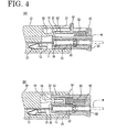
- FIGS. 4A and 4B are a section along X-X showing a state where a lock arm is elastically deformed to engage a slider, and a section along Y-Y showing a state at an intermediate stage of connection of the housings, respectively,
- FIGS. 5A and 5B are a section along X-X showing a state where the slider is moved backward by being pushed by the lock arm, and a section along Y-Y showing a state where compression coil springs are elastically compressed, respectively,
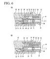
- FIGS. 6A and 6B are sections along X-X, Y-Y showing a state where the housings are properly connected, respectively,
- FIGS. 7A and 7B are a section along X-X showing a state where the slider is moved backward, and a section along Y-Y showing a state where the compression coil springs are elastically compressed, respectively,
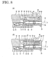
- FIGS. 8A and 8B are sections along X-X, Y-Y showing an intermediate stage of separation, respectively, and
- FIG. 9 is a side view in section of a prior art connector.
-
- One preferred embodiment of the present invention is described with reference to FIGS. 1 to 8. As shown in FIG. 3, a connector of this embodiment is comprised of a male connector housing 10 (hereinafter, merely "
male housing 10") and a female connector housing 30 (hereinafter, merely "female housing 30"), themale housing 10 being provided with alock arm 18, and aslider 51 being mounted in thefemale housing 30 via compression coil springs 50. In the following description, sides of thehousings - The
male housing 10 is, as shown in FIGS. 1 and 3, provided with areceptacle 11 integrally or unitarily formed e.g. of a synthetic resin with a wall surface of an equipment and substantially in the form of a substantially rectangular tube projecting forward. Thefemale housing 30 is at least partly fittable or insertable into thereceptacle 11 from front. E.g. fourmale tab terminals 12 arranged preferably substantially side by side along widthwise direction project from a back wall of themale housing 10. Thesetab terminals 12 project into thereceptacle 11 and are electrically connectable with femaleterminal fittings 31 of thefemale housing 30. A shortingterminal 13 is preferably accommodated in the back wall of themale housing 10 preferably below themale tab terminals 12. The shortingterminal 13 is preferably provided with a substantially plate-shapedmain portion 14 and a corresponding number of, e.g. four elastic orresilient contact pieces 15 folded at the rear end of themain portion 15 to project substantially forward. Themain portion 15 of the shortingterminal 13 is pressed or fitted into amount groove 16 which substantially is in flush with the inner surface of thereceptacle 11, and the respectiveelastic contact pieces 15 are at least partly accommodated inaccommodating recesses 17 which are so formed as to face the respectivemale tab terminals 12, and are resiliently or elastically held in contact with the respectivemale tab terminals 12. In this way, the fourmale tab terminals 12 are shorted with each other so as to cause no potential difference among them. Since the respectiveelastic contact pieces 15 are arranged such that their front portions project into thereceptacle 11 and their leading ends 15a are bent down, they are elastically or resiliently pushed down or away from themale tab terminals 12 to separate from themale tab terminals 12 by thefemale housing 30 fitted into thereceptacle 11. - The
lock arm 18 in the form of a cantilever projects preferably substantially from a widthwise center position of the back wall of themale housing 10 above themale tab terminals 12 or on a side thereof opposing the shortingterminal 13. Thelock arm 18 projects slightly more forward than themale tab terminals 12, and is elastically or resiliently deformable or displaceable about its base end along vertical direction in FIGURES or a displacement direction D which is a direction intersecting with a connecting and separating direction CSD or arranged at an angle different from 0° or 180°, preferably substantially normal to the connection direction. Ahook portion 19 projecting down is formed at a free end (front end) of thelock arm 18. The fittedhousings rear end surface 20 of thehook portion 19 with arear end surface 40 of a bulgingportion 38 of thefemale housing 30 to be described later. - A
notch 21 for permitting entrance of anoperable portion 55 of theslider 51 of thefemale housing 30 to be described later is formed in a corresponding position, preferably substantially in a widthwise center position of the upper wall of thereceptacle 11. A length of thisnotch 21 is substantially equal to a moving stroke of theslider 51. Thelock arm 18 is located behind the rear end surface of thenotch 21 and is substantially completely laterally surrounded by the wall surfaces of thereceptacle 11. Further, opposite side ends of the bottom of thereceptacle 11 project downward and a pair of guide recesses 22 for receivingguide ribs 36 of thefemale housing 30 are formed therein. - As shown in FIGS. 2 and 3, the
female housing 30 is formed e.g. of a synthetic resin preferably into a substantially block shape, andcavities 32 for at least partly accommodating the femaleterminal fittings 31 connected or connectable with ends of wires W penetrate through thefemale housing 30 substantially in forward and backward or longitudinal directions. E.g. fourcavities 32 are formed substantially side by side in widthwise direction in positions in alignment with the matingmale tab terminals 12. Aretainer mount hole 33 crossing therespective cavities 32 is preferably formed in one side of thefemale housing 30, and aretainer 34 which projects or can project into therespective cavities 32 to directly lock the femaleterminal fittings 31 is mounted or mountable in thisretainer mount hole 33. E.g. fourengaging recesses 35 engageable with the respectiveelastic contact pieces 15 of the shortingterminal 13 arranged in themale housing 10 are formed substantially side by side in the bottom surface of thefemale housing 30, and engagingsurfaces 15a thereof with theelastic contact pieces 15 are slanted downward to the right as shown in FIG. 3 or away from themale tab terminals 12 so that theelastic contact pieces 15 can be smoothly elastically or resiliently deformed downward. The pair ofguide ribs 36 capable of guiding the connection of thehousings male housing 10 project down at the opposite side ends of the bottom surface of thefemale housing 30. Anoperable rib 37 extending in widthwise direction projects down from the rear end of the bottom surface of thefemale housing 30. Thefemale housing 30 is or can be connected with and separated from themale housing 10 by gripping thisoperable rib 37. - In a widthwise center position of the upper surface of the
female housing 30, the bulgingportion 38 bulges up to the same height or radial position (height or radial position overlapping with the hook portion 19) as the lower surface of an arm portion of thelock arm 18 of themale housing 10. Behind the bulgingportion 38, an escape groove or recess or notch 39 for permitting the entrance of thehook portion 19 of thelock arm 18 extends backward or away from themale connector housing 10. With thehousings rear end surface 20 of thehook portion 19 of thelock arm 18 is engaged or engageable with therear end surface 40 of the bulging portion 38 (front end surface of the escape groove 39) for locking (see FIG. 6). The locking surfaces 20, 40 (rear end surfaces) of thehook portion 19 and the bulgingportion 38 are moderately sloped or rounded upward to the left in FIGURES, thereby forming a semi-locking construction or releasable locking construction. In other others, when such a specified (predetermined or predeterminable) force or larger as to separate thehousings hook portion 19 engaged with the bulgingportion 38, thelock arm 18 is automatically elastically or resiliently deformed or displaced upward while being freed from the locked state by being guided by the slanted or rounded guide surfaces of the locking surfaces 20, 40. - A pair of
side walls 41 project upward or laterally at the substantially opposite side ends of the upper surface of thefemale housing 30, a pair ofceiling walls 42 project toward each other from the upper ends of theside walls 41, and arear wall 43 extending in widthwise direction is so provided at the rear end of the upper surface of thefemale housing 30 as to be connected with theside walls 41 and theceiling walls 42. As shown in FIG. 3, theslider 51 accommodating the compression coil springs 50 is assembled from front into a space above thefemale housing 30 surrounded by theside walls 41, theceiling walls 42 and therear wall 43, and is movable in forward and backward or longitudinal directions substantially along the connecting direction of thehousings female housing 30, the side edges of the bulgingportion 38, theside walls 41 and theceiling walls 42. - The
slider 51 is formed e.g. of a synthetic resin and is constructed such thatspring accommodating portions 52 for at least partly accommodating a pair of compression coil springs 50 are formed at its opposite ends and are bridged or connected by acoupling portion 53 in the middle. As shown in FIG. 3B, rear parts of thespring accommodating portions 52 are so recessed as to at least partly accommodate the compression coil springs 50 while slightly compressing them along a longitudinal direction thereof between the rear surfaces of thespring accommodating portions 52 and the front end surface of therear wall 43. By moving theslider 51 backward in this state, the compression coil springs 50 can be elastically or resiliently deformed while storing even larger spring forces (see FIG. 5(B)). A pair ofstopper projections 54 project sideways from the opposite side surfaces of theslider 51 as shown in FIG. 2. The front end surface ofslider 51 is stopped at its limit position which is slightly retracted from the front end surface of thefemale housing 30 by introducing thestopper projections 54 intostopper grooves 44 formed in theside walls 41 and bringing them into engagement of the front end surfaces of thestopper grooves 44 whereby a range of movement of theslider 51 is limited by thestopper projections 54 and thestopper grooves 44 acting as preferred movement range limiting means. - The
coupling portion 53 of theslider 51 has a lower surface substantially at the same height or radial position as the upper surface of thelock arm 18 in its natural or undeflected or undeformed state as shown in FIG. 3(A). Accordingly, when thelock arm 18 is elastically or resiliently deformed or displaced to displace its free end upward or to radially displacing the free end thereof, the front end surface of thelock arm 18 is engageable with the front end surface of thecoupling portion 53. The position of thelock arm 18 at this time is referred to as an engaging or first position (see FIG. 5(A)). On the other hand, the position of thelock arm 18 where it is in its natural state and cannot be engaged with the front end surface of thecoupling portion 53 of theslider 51 is referred to as a disengaging or second position. Since thecoupling portion 53 of theslider 51 is located above or radially outward thelock arm 18 preferably substantially over its entire length with thehousings lock arm 18 engaged with the bulgingportion 38 from being elastically deformed upward (see FIG. 6). - The
operable portion 55 pushed to forcibly move theslider 51 back against the biasing forces of the compression coil springs 50 projects up from the upper surface at the rear end of thecoupling portion 53. Theoperable portion 55 has a height or radial extension set such that it projects out from the upper surface of the male housing 10 (outer contour of the connector) through the space between theceiling walls 42 and thenotch 21 of themale housing 10 with thehousings operable portion 55 is substantially held in sliding contact with the respective side edges of theceiling walls 42 and thenotch 21 while theslider 51 is moved forward and backward. - How this embodiment thus constructed acts is described next. The
housings female housing 30 is fitted into thereceptacle 11 of themale housing 10 after the male andfemale housings male tab terminals 12 enter thecavities 32 of thefemale housing 30, thelock arm 18 engages the front end surface of the bulgingportion 38 to be elastically or resiliently deformed to the engaging or first position while moving onto the upper or lateral surface of the bulgingportion 38. Thereafter, the front end surface of thelock arm 18 is engaged with the front end surface of thecoupling portion 53 of theslider 51 located at the position slightly retracted from the front end surface of the bulgingportion 38. If connection is further proceeded in this state, theterminal fittings slider 51 is pushed back by thelock arm 18 located in its engaging position as shown in FIG. 5. As a result, theslider 51 is moved backward while elastically compressing the compression coil springs 50. - The connecting operation may be interrupted halfway. In such a case, the spring forces accumulated in the elastically compressed coil springs 50 are released, and the
slider 51 biased forward pushes thelock arm 18 to forcibly separate thehousings housings - As the connecting operation is continued, the engaging
recesses 35 of thefemale housing 30 come into engagement with the respectiveelastic contact pieces 15 of the shortingterminal 13 to elastically deform them downward or away from themale tab terminal 12 so as to be disengaged from themale tab terminals 12. As a result, the shorted state of the respectivemale tab terminals 12 can be canceled (see FIG. 6). When thehousing 30 is fitted into thehousing 10 to a proper depth, thehook portion 19 enters theescape groove 39 and thelock arm 18 is elastically or resiliently restored to its disengaging or second position to engage therear end surface 20 of thehook portion 19 with therear end surface 40 of the bulging portion 38 (front end surface of the escape groove 39) as shown in FIG. 6. Simultaneously, theslider 51 disengaged from thelock arm 18 is moved forward by the released spring forces accumulated in the compression coil springs 50, and is stopped at the same position as it was before thehousings stopper projections 54 coming into contact with the front end surfaces of thestopper grooves 44. At this time, thecoupling portion 53 of theslider 51 covering thelock arm 18 substantially over its entire length prevents thelock arm 18 located in the disengaging position from being elastically or resiliently deformed upward. In this way, thehousings lock arm 18 and the bulgingportion 38 are engaged and thelock arm 18 is prevented from being elastically or resiliently deformed in unlocking direction by theslider 51. Accordingly, the radial engagement of thelock arm 18 with the slider 51 (or radial abutting of thelock arm 18 on the slider 51) prevents an unlocking of theconnector housings operable portion 55 of theslider 51 is located in thenotch 21 of thereceptacle 11 and its front end surface is held in contact with or in proximity to the front end surface of thenotch 21. - On the other hand, there are cases where the
housings slider 51 is moved backward while elastically compressing the coil springs 50 by pushing theoperable portion 55 of theslider 51 projecting upward from thereceptacle 11, and thefemale housing 30 is pulled in separating direction by gripping theoperable rib 37 of thefemale housing 30. When thecoupling portion 53 of theslider 51 is moved back to a position where it is no longer located above the lock arm 18 (simultaneously, the front end surface of theoperable portion 55 preferably becomes substantially in flush with the front end surface of the receptacle 11), thelock arm 18 is automatically elastically or resiliently deformed upward or in a radial direction by a pulling force acting on thefemale housing 30 in separating direction while being guided by the slanted guide surfaces 20, 40 of thehook portion 19 and the bulgingportion 38. As thefemale housing 30 is moved away from themale housing 10, the locking surfaces 20, 40 of thehook portion 19 and the bulgingportion 38 are disengaged from each other as shown in FIG. 8 and thefemale housing 30 is pulled out in this state. During this process, the respectiveelastic contact pieces 15 of the shortingterminal 13 are disengaged from the engagingrecesses 35 to be brought again into elastic contact with the respectivemale tab terminals 12. Since the moving direction of theslider 51 and the pulling direction of thefemale housing 30 coincide at this time, the separating operation can be easily performed. - The separating operation may also be interrupted halfway for a certain reason. In such a case, the spring forces accumulated in the elastically compressed coil springs 50 are released, thereby moving the
slider 51 forward and striking it against the front end surface of thelock arm 18 in the engaging position as indicated in phantom in FIG. 8. As a result, thehousings slider 51 biased by the compression coil springs 50 strikes against arounded portion 18a at the upper front end of thelock arm 18 when the separating operation is interrupted with thefemale housing 30 slightly moved in separating direction from its connected state with themale housing 10 and with thelock arm 18 slightly elastically deformed, thelock arm 18 is guided to its disengaging position and thehousings housings - As described above, according to this embodiment, partial connection of the
housings lock arm 18 is provided with a function of inseparably holding thehousings slider 51, the construction of the connector can be simplified as compared to a case where separate parts bear these two functions. Furthermore, since theoperable portion 55 for forcibly moving theslider 51 backward during the separating operation projects out from the outer contour of the connector, the separating operation can be easily performed. - The present invention is not limited to the above described and illustrated embodiment. For example, following embodiments are also embraced by the technical scope of the present invention as defined in the claims. Beside the following embodiments, various changes can be made without departing from the scope and spirit of the present invention as defined in the claims.
- (1) Although the compression coil springs are mounted behind the slider in the foregoing embodiment, they may be mounted before the slider according to the present invention.
- (2) Contrary to the foregoing embodiment, the slider and the compression coil springs may be mounted in the male housing and the lock arm may be provided at the female housing according to the present invention.
- (3) Although the male housing is integrally or unitarily formed with the equipment in the foregoing embodiment, the male housing may be, for example, provided at an end of a wire drawn from an equipment or may be an intermediate connector.
- (4) In the foregoing embodiment, the compression coil springs may be deleted e.g. if there is a demand to reduce production costs. In such a case, the connected state of the housings can be detected during the connecting operation based on whether or not the slider can be moved forward by constantly pushing the slider forward. On the other hand, by pulling the female housing in separating direction and pushing the slider forward after moving the slider backward up to a position where it is disengaged from the lock arm, it can be detected that the separating operation is halfway while the forward movement of the slider is restricted by its engagement with the lock arm.
-
-
- 10
- male housing (other connector housing)
- 18
- lock arm (elastically engaging portion)
- 20
- rear end surface (guide surface)
- 30
- female housing (one connector housing)
- 40
- rear end surface (guide surface)
- 50
- compression coil spring (biasing means)
- 51
- slider
- 55
- operable portion
Claims (16)
- A connector having at least one pair of connector housings (10, 30) at least partly connectable with each other, comprising:whereinthe resiliently engaging portion (18) is resiliently displaceable between a first position when the pair of connector housings (10, 30) are partially connected and a second position when the pair of connector housings (10, 30) are substantially fully connected, and wherein when the resiliently engaging portion (18) is positioned in the first position it is engageable with an engaging portion (53) of the slider (51) along the connecting and separating directions (CSD), the engaging portion (53) being provided in the middle of the slider (51),a slider (51) assembled in a first connector housing (30) of the pair of connector housings (10, 30) and movable forward and backward along connecting and separating directions (CSD) of the connector housings (10, 30), anda single resiliently engaging portion (18) provided in a second connector housing (10) of the pair of connector housings (10, 30)
characterised in that
when the resiliently engaging portion (18) is positioned in the second position it can be accommodated in an accommodating space defined in the slider (51) radially inward of the engaging portion (53). - A connector according to claim 1, wherein the resiliently engaging portion (18) is resiliently displaceable in a direction (D) intersecting with the connecting and separating directions (CSD).
- A connector according to one or more of the preceding claims, wherein the slider (51) engaged with the resiliently engaging portion (18) located in the first position can be moved backward both at an intermediate stage of an operation of connecting the connector housings (10, 30) and at an intermediate stage of an operation of separating the connector housings (10, 30).
- A connector according to one or more of the preceding claims, wherein when the resiliently engaging portion (18) is positioned in the second position it is not engageable with the slider (51) along the connecting and separating directions (CSD).
- A connector according to one or more of the preceding claims, wherein when the connector housings (10, 30) are substantially properly connected with each other, the resiliently engaging portion (18) is not engageable with the slider (51) along the connecting and separating directions (CSD) by being resiliently displaced to the second position and the slider (51) can be moved forward.
- A connector according to one or more of the preceding claims, wherein:the slider (51) is assembled into the first connector housing (30) via a biasing means (50),the slider (51) engaged with the resiliently engaging portion (18) located in the first position can be moved backward against a biasing force of the biasing means (50) both at an intermediate stage of an operation of connecting the connector housings (10, 30) and at an intermediate stage of an operation of separating the connector housings (10, 30), andwhen the connector housings (10, 30) are substantially properly connected with each other (FIG. 6), the slider (51) is moved forward by the release of the biasing force accumulated in the biasing means (50).
- A connector according to one or more of the preceding claims, wherein the resiliently engaging portion (18) comprises a lock arm (18) which is resiliently displaced from the second position to the first position by moving onto the first connector housing (30) at the intermediate stage of the connecting or separating operation of the connector housings (10, 30), and is resiliently displaced from the first position to the second position and is engaged with the first connector housing (30) to hold the connector housings (10, 30) locked into each other when the connector housings (10, 30) are substantially properly connected with each other.
- A connector according to claim 7, wherein when located in the second position the resiliently engaging portion (18) engages the slider (51) in a direction (D) at an angle different from 0° or 180°, preferably substantially normal to the connecting and separating directions (CSD) so as to prevent the displacement of the resiliently engaging portion (18) to unlock the housings (10, 30) from each other.
- A connector according to one or more of the preceding claims, wherein the slider (51) comprises an operable portion (55) for moving the slider (51) backward preferably against the biasing force of the biasing means (50), the operable portion (55) being so formed as to project out from the connector.
- A connector according to one or more of the preceding claims, wherein the slider (51) is located in such a position as to restrict a resilient displacement of the resiliently engaging portion (18) engaged with the first connector housing (30) when the connector housings (10, 30) are properly connected with each other.
- A connector according to claim 10, wherein engaging portions (20, 40) of the resiliently engaging portion (18) and the first connector housing (30), respectively engageable with each other are formed with guide surfaces (20, 40) capable of guiding a resilient displacement of the resiliently engaging portion (18) from the second position to the first position only when the connector housings (10, 30) are pulled in separating direction with a specified force or larger.
- A connector according to one or more of the preceding claims, wherein the slider (51) is movable in a disconnecting direction of the first connector housing (30) from the second connector housing (10) to thereby allow a resilient displacement of the resiliently engaging portion (18) to unlock the connector housings (10, 30) from each other.
- A connector according to one or more of the preceding claims, wherein the resiliently engaging portion (18) comprises a guiding portion (18a) for coming into contact with the slider (51) so as to urge the resiliently engaging portion (18) towards the second position
- A connector according to one or more of the preceding claims, wherein the resiliently engaging portion (18) is provided in a receptacle (11) of the second housing (10) into which the fist housing (30) is at least partly insertable.
- A method of assembling a connector having at least one pair of connector housings (10, 30) at least partly connectable with each other, comprising the following steps:characterised byat least partly connecting a first connector housing (30) with a second connector housing (10) of the pair of connector housings (10, 30) thereby bringing a single resiliently engaging portion (18) provided in the second connector housing (10) into engagement with a portion (38) of the first housing (30) to displace the resiliently engaging portion (18) from a second position where it is not engageable with the slider (51) along connecting and separating directions (CSD) of the connector housings (10, 30), to a first position thereby engaging a portion (53) of the slider (51) provided in the middle thereof,
accommodating the resiliently engaging portion (18) in an accommodating space defined in the slider (51) radially inward of the engaging portion (53), when the resiliently engaging portion (18) is positioned in the second position - A method according to claim 15, wherein the slider (51) engaged with the resiliently engaging portion (18) located in the first position is moved backward both at an intermediate stage of an operation of connecting the connector housings (10, 30) and at an intermediate stage of an operation of separating the connector housings (10, 30), and/or
when the connector housings (10, 30) are substantially properly connected with each other the resiliently engaging portion (18) is not engageable with the slider (51) along the connecting and separating directions (CSD) by being resiliently displaced to the second position and the slider (51) is moved forward.
Priority Applications (2)
| Application Number | Priority Date | Filing Date | Title |
|---|---|---|---|
| DE20121621U DE20121621U1 (en) | 2001-02-16 | 2001-10-01 | Connector and connector housing with connection detection function |
| EP20030008174 EP1333542A1 (en) | 2001-02-16 | 2001-10-01 | a connector |
Applications Claiming Priority (2)
| Application Number | Priority Date | Filing Date | Title |
|---|---|---|---|
| JP2001040822A JP3656830B2 (en) | 2001-02-16 | 2001-02-16 | connector |
| JP2001040822 | 2001-02-16 |
Related Child Applications (1)
| Application Number | Title | Priority Date | Filing Date |
|---|---|---|---|
| EP20030008174 Division EP1333542A1 (en) | 2001-02-16 | 2001-10-01 | a connector |
Publications (3)
| Publication Number | Publication Date |
|---|---|
| EP1233480A1 EP1233480A1 (en) | 2002-08-21 |
| EP1233480B1 true EP1233480B1 (en) | 2003-06-11 |
| EP1233480B8 EP1233480B8 (en) | 2003-12-03 |
Family
ID=18903350
Family Applications (2)
| Application Number | Title | Priority Date | Filing Date |
|---|---|---|---|
| EP01123222A Expired - Lifetime EP1233480B8 (en) | 2001-02-16 | 2001-10-01 | A connector and a method of assembling a connector |
| EP20030008174 Withdrawn EP1333542A1 (en) | 2001-02-16 | 2001-10-01 | a connector |
Family Applications After (1)
| Application Number | Title | Priority Date | Filing Date |
|---|---|---|---|
| EP20030008174 Withdrawn EP1333542A1 (en) | 2001-02-16 | 2001-10-01 | a connector |
Country Status (5)
| Country | Link |
|---|---|
| US (1) | US6685500B2 (en) |
| EP (2) | EP1233480B8 (en) |
| JP (1) | JP3656830B2 (en) |
| AT (1) | ATE256379T1 (en) |
| DE (2) | DE20121621U1 (en) |
Families Citing this family (19)
| Publication number | Priority date | Publication date | Assignee | Title |
|---|---|---|---|---|
| US6776645B2 (en) * | 2002-12-20 | 2004-08-17 | Teradyne, Inc. | Latch and release system for a connector |
| JP4179129B2 (en) * | 2003-10-09 | 2008-11-12 | 住友電装株式会社 | connector |
| US6827609B1 (en) * | 2003-11-12 | 2004-12-07 | Tyco Electronics Corporation | Electrical connector having improved terminal positioning assurance member |
| FR2870647B1 (en) * | 2004-05-19 | 2006-08-25 | Cie Deutsch Societe Par Action | AUTO-CENTER CONNECTOR WITH INERTIAL LOCK |
| FR2944388B1 (en) * | 2009-04-10 | 2011-05-20 | Tyco Electronics France Sas | ELECTRICAL CONNECTOR |
| JP5653150B2 (en) * | 2010-09-16 | 2015-01-14 | 矢崎総業株式会社 | Half-mating prevention connector |
| JP5646273B2 (en) * | 2010-10-07 | 2014-12-24 | 矢崎総業株式会社 | connector |
| TWM458000U (en) * | 2013-01-11 | 2013-07-21 | Molex Taiwan Ltd | Electrical connection device |
| TWM462985U (en) * | 2013-04-09 | 2013-10-01 | Molex Taiwan Ltd | Electrical connection device |
| CN105191010B (en) * | 2013-05-08 | 2017-08-25 | 住友电装株式会社 | Connector |
| US8968021B1 (en) | 2013-12-11 | 2015-03-03 | JAE Oregon, Inc. | Self-rejecting automotive harness connector |
| US9356394B2 (en) | 2013-12-11 | 2016-05-31 | JAE Oregon, Inc. | Self-rejecting connector |
| US9318836B2 (en) * | 2014-02-06 | 2016-04-19 | Dai-Ichi Seiko Co., Ltd. | Electric connector |
| JP6287987B2 (en) * | 2015-07-22 | 2018-03-07 | 住友電装株式会社 | connector |
| CN108832391B (en) * | 2018-07-20 | 2024-04-02 | 浩亭(珠海)制造有限公司 | Quick push-pull connector, connector assembly and unlocking method |
| JP7230739B2 (en) | 2019-08-09 | 2023-03-01 | 住友電装株式会社 | connector |
| JP7232407B2 (en) * | 2019-08-09 | 2023-03-03 | 住友電装株式会社 | connector |
| JP7384613B2 (en) | 2019-10-07 | 2023-11-21 | 矢崎総業株式会社 | connector |
| US11876324B2 (en) * | 2021-07-29 | 2024-01-16 | Aptiv Technologies AG | Self-ejecting electrical connection system |
Family Cites Families (9)
| Publication number | Priority date | Publication date | Assignee | Title |
|---|---|---|---|---|
| US5370543A (en) | 1992-07-24 | 1994-12-06 | Fujikura Ltd. | Electrical connector |
| US5672073A (en) * | 1994-06-14 | 1997-09-30 | Yazaki Corporation | Connector having engagement detecting device |
| JP3503729B2 (en) * | 1996-11-08 | 2004-03-08 | 住友電装株式会社 | connector |
| DE19714459C2 (en) * | 1997-04-08 | 2001-11-29 | Framatome Connectors Int | Connector with a housing lock |
| JP3420918B2 (en) * | 1997-09-17 | 2003-06-30 | 矢崎総業株式会社 | Half mating prevention connector |
| JP3278051B2 (en) * | 1997-12-25 | 2002-04-30 | 住友電装株式会社 | Connector with cover |
| JP2000113935A (en) * | 1998-10-05 | 2000-04-21 | Yazaki Corp | Halfway fitting preventing connector and manufacture thereof |
| DE19847872A1 (en) | 1998-10-16 | 2000-05-04 | Framatome Connectors Int | Ignition bus contact housing, especially for airbag applications |
| JP2001085109A (en) | 1999-09-13 | 2001-03-30 | Sumitomo Wiring Syst Ltd | Connector |
-
2001
- 2001-02-16 JP JP2001040822A patent/JP3656830B2/en not_active Expired - Fee Related
- 2001-10-01 DE DE20121621U patent/DE20121621U1/en not_active Expired - Lifetime
- 2001-10-01 EP EP01123222A patent/EP1233480B8/en not_active Expired - Lifetime
- 2001-10-01 AT AT01123222T patent/ATE256379T1/en active
- 2001-10-01 DE DE60100355T patent/DE60100355T2/en not_active Expired - Lifetime
- 2001-10-01 EP EP20030008174 patent/EP1333542A1/en not_active Withdrawn
- 2001-10-30 US US10/013,611 patent/US6685500B2/en not_active Expired - Fee Related
Also Published As
| Publication number | Publication date |
|---|---|
| EP1233480A1 (en) | 2002-08-21 |
| DE20121621U1 (en) | 2003-01-09 |
| EP1333542A1 (en) | 2003-08-06 |
| US20020115338A1 (en) | 2002-08-22 |
| ATE256379T1 (en) | 2003-12-15 |
| EP1233480B8 (en) | 2003-12-03 |
| US6685500B2 (en) | 2004-02-03 |
| JP3656830B2 (en) | 2005-06-08 |
| DE60100355T2 (en) | 2004-04-29 |
| JP2002246110A (en) | 2002-08-30 |
| DE60100355D1 (en) | 2003-07-17 |
Similar Documents
| Publication | Publication Date | Title |
|---|---|---|
| EP1233480B1 (en) | A connector and a method of assembling a connector | |
| US6712635B1 (en) | Connector | |
| US6688907B2 (en) | Connector and a connector assembly | |
| US6533600B1 (en) | Connector fitting construction | |
| JP3467202B2 (en) | Connector locking mechanism | |
| US6019629A (en) | Connector | |
| EP1638175A2 (en) | A connector and a connector assembly | |
| US20040102075A1 (en) | Connector and a connector assembly | |
| US7059902B2 (en) | Connector, a connector assembly and a method of assembling a connector assembly | |
| US20040038569A1 (en) | Connector and a connector assembly | |
| US6595795B2 (en) | Connector and a method of assembling a connector | |
| US6551146B2 (en) | Connector and a method for assembling a connector | |
| JP3437102B2 (en) | Half mating prevention connector | |
| US20040106330A1 (en) | Connector | |
| EP1780839B1 (en) | Connector | |
| US20030186579A1 (en) | Connector and a connector assembly | |
| US6572394B1 (en) | Connector and use thereof | |
| US6679720B2 (en) | Connector and a method for assembling a connector | |
| EP1523072B1 (en) | A connector, a connector assembly and an assembling method | |
| US6530800B2 (en) | Connector and method for assembling a connector | |
| US7074069B2 (en) | Connector and a connector assembly | |
| US6325663B1 (en) | Half-fitting prevention connector | |
| US6953364B2 (en) | Connector, a shorting terminal and a method of assembling it | |
| US6666710B2 (en) | Connector and a connector assembly | |
| US6319041B1 (en) | Connector with positive locking features |
Legal Events
| Date | Code | Title | Description |
|---|---|---|---|
| PUAI | Public reference made under article 153(3) epc to a published international application that has entered the european phase |
Free format text: ORIGINAL CODE: 0009012 |
|
| 17P | Request for examination filed |
Effective date: 20011025 |
|
| AK | Designated contracting states |
Kind code of ref document: A1 Designated state(s): AT BE CH CY DE DK ES FI FR GB GR IE IT LI LU MC NL PT SE TR |
|
| AX | Request for extension of the european patent |
Free format text: AL;LT;LV;MK;RO;SI |
|
| GRAH | Despatch of communication of intention to grant a patent |
Free format text: ORIGINAL CODE: EPIDOS IGRA |
|
| 17Q | First examination report despatched |
Effective date: 20021011 |
|
| GRAH | Despatch of communication of intention to grant a patent |
Free format text: ORIGINAL CODE: EPIDOS IGRA |
|
| GRAA | (expected) grant |
Free format text: ORIGINAL CODE: 0009210 |
|
| AKX | Designation fees paid |
Designated state(s): AT DE FR |
|
| AK | Designated contracting states |
Designated state(s): DE FR |
|
| RBV | Designated contracting states (corrected) |
Designated state(s): DE FR |
|
| RBV | Designated contracting states (corrected) |
Designated state(s): AT DE FR |
|
| REF | Corresponds to: |
Ref document number: 60100355 Country of ref document: DE Date of ref document: 20030717 Kind code of ref document: P |
|
| RBV | Designated contracting states (corrected) |
Designated state(s): AT DE FR |
|
| ET | Fr: translation filed | ||
| PLBE | No opposition filed within time limit |
Free format text: ORIGINAL CODE: 0009261 |
|
| STAA | Information on the status of an ep patent application or granted ep patent |
Free format text: STATUS: NO OPPOSITION FILED WITHIN TIME LIMIT |
|
| 26N | No opposition filed |
Effective date: 20040312 |
|
| PGFP | Annual fee paid to national office [announced via postgrant information from national office to epo] |
Ref country code: AT Payment date: 20130926 Year of fee payment: 13 |
|
| PGFP | Annual fee paid to national office [announced via postgrant information from national office to epo] |
Ref country code: FR Payment date: 20141008 Year of fee payment: 14 |
|
| REG | Reference to a national code |
Ref country code: AT Ref legal event code: MM01 Ref document number: 256379 Country of ref document: AT Kind code of ref document: T Effective date: 20141001 |
|
| PG25 | Lapsed in a contracting state [announced via postgrant information from national office to epo] |
Ref country code: AT Free format text: LAPSE BECAUSE OF NON-PAYMENT OF DUE FEES Effective date: 20141001 |
|
| REG | Reference to a national code |
Ref country code: FR Ref legal event code: ST Effective date: 20160630 |
|
| PG25 | Lapsed in a contracting state [announced via postgrant information from national office to epo] |
Ref country code: FR Free format text: LAPSE BECAUSE OF NON-PAYMENT OF DUE FEES Effective date: 20151102 |
|
| PGFP | Annual fee paid to national office [announced via postgrant information from national office to epo] |
Ref country code: DE Payment date: 20160927 Year of fee payment: 16 |
|
| REG | Reference to a national code |
Ref country code: DE Ref legal event code: R119 Ref document number: 60100355 Country of ref document: DE |
|
| PG25 | Lapsed in a contracting state [announced via postgrant information from national office to epo] |
Ref country code: DE Free format text: LAPSE BECAUSE OF NON-PAYMENT OF DUE FEES Effective date: 20180501 |