US5326085A - Device for supporting slabs during the phases of punching and in general operations of plastic deformation - Google Patents
Device for supporting slabs during the phases of punching and in general operations of plastic deformation Download PDFInfo
- Publication number
- US5326085A US5326085A US08/024,513 US2451393A US5326085A US 5326085 A US5326085 A US 5326085A US 2451393 A US2451393 A US 2451393A US 5326085 A US5326085 A US 5326085A
- Authority
- US
- United States
- Prior art keywords
- slab
- jacks
- plastic deformation
- punching
- operations
- Prior art date
- Legal status (The legal status is an assumption and is not a legal conclusion. Google has not performed a legal analysis and makes no representation as to the accuracy of the status listed.)
- Expired - Fee Related
Links
Images

Classifications
-
- B—PERFORMING OPERATIONS; TRANSPORTING
- B21—MECHANICAL METAL-WORKING WITHOUT ESSENTIALLY REMOVING MATERIAL; PUNCHING METAL
- B21D—WORKING OR PROCESSING OF SHEET METAL OR METAL TUBES, RODS OR PROFILES WITHOUT ESSENTIALLY REMOVING MATERIAL; PUNCHING METAL
- B21D43/00—Feeding, positioning or storing devices combined with, or arranged in, or specially adapted for use in connection with, apparatus for working or processing sheet metal, metal tubes or metal profiles; Associations therewith of cutting devices
-
- B—PERFORMING OPERATIONS; TRANSPORTING
- B21—MECHANICAL METAL-WORKING WITHOUT ESSENTIALLY REMOVING MATERIAL; PUNCHING METAL
- B21D—WORKING OR PROCESSING OF SHEET METAL OR METAL TUBES, RODS OR PROFILES WITHOUT ESSENTIALLY REMOVING MATERIAL; PUNCHING METAL
- B21D28/00—Shaping by press-cutting; Perforating
- B21D28/24—Perforating, i.e. punching holes
- B21D28/26—Perforating, i.e. punching holes in sheets or flat parts
-
- B—PERFORMING OPERATIONS; TRANSPORTING
- B23—MACHINE TOOLS; METAL-WORKING NOT OTHERWISE PROVIDED FOR
- B23Q—DETAILS, COMPONENTS, OR ACCESSORIES FOR MACHINE TOOLS, e.g. ARRANGEMENTS FOR COPYING OR CONTROLLING; MACHINE TOOLS IN GENERAL CHARACTERISED BY THE CONSTRUCTION OF PARTICULAR DETAILS OR COMPONENTS; COMBINATIONS OR ASSOCIATIONS OF METAL-WORKING MACHINES, NOT DIRECTED TO A PARTICULAR RESULT
- B23Q1/00—Members which are comprised in the general build-up of a form of machine, particularly relatively large fixed members
- B23Q1/03—Stationary work or tool supports
- B23Q1/035—Stationary work or tool supports with an array of longitudinally movable rods defining a reconfigurable support surface
Definitions
- the present invention relates to a device capable of supporting slabs during the phases of punching and in general operations of plastic deformation.
- Metallic slabs which may have, but not necessarily, a planer surface are used to produce a great number of apparatuses for both domestic as well as industrial use, such as for instance, refrigerators, washing machines, furniture, etc. Very frequently these slabs must be punched or in any event subjected to operations of plastic deformation, which operations, to a great extent, are carried out with machines which comprise a turret provided with a great number of tools for the purpose of carrying out the several operations on the surface of the slab.
- the slab in addition is placed in motion by a suitable manipulator along two axes and the entire assembly is regulated by a control device which operates in such a manner that the desired operations may be carried out in sequence on the several areas which have been previously selected on the slab being worked.
- the crucial feature inherent to these devices consists of the supporting plane for the same slab.
- planes equipped with anti-friction supporting means for the slabs may comprise load bearing balls of the type with recirculation or brushes with bristles for supporting the slabs or other supporting means.
- the object of the present invention is to provide a supporting device for the slab during the phases of punching and operations of plastic deformation in general, which device permits to carry out these operations without limitation with respect to the depth. Further, the device according to the present invention is simple from the constructive as well as the functional point of view and permit it to be operated quickly.
- the crux of the present invention resides in providing the supporting device with a plurality of jacks which are placed under the slab corresponding at least to a substantial portion of the entire surface of the slab. These jacks are placed at a distance among themselves which is substantially less than the extension of the two main dimensions of the slab.
- Every one of these jacks has a stem which ends in the upper part with a mushroom head and at the top of the head there is provided a device of the blow-by balls. Every one of the heads under normal conditions is placed in contact with the lower surface of the slab.
- a control system for controlling the jacks capable of lowering the stems of the jacks for the purpose of avoiding interference between the heads of the jacks and the portions of the slab which have already been deformed downwardly.
- the device according to the present invention is capable of avoiding the drawbacks previously described, particularly allowing operations of plastic deformation without any limitation with respect to the depth.
- Another advantage of the present invention is that the apparatus is simple from both the constructive point of view as well as the functional point of view.
- Still another advantage is that the jacks, particularly the jacks of the pneumatic type, are capable of operating with great speed, thus permitting to carry out the desired operation of plastic deformation without causing inconvenience with respect to the potential operativeness of the equipment required for the operation.
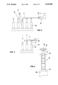
- FIG. 1 illustrates a top plan view of the device of the invention and the tools being used for imparting motion as well as tools required for the plastic deformation of the slab.
- FIGS. 2 and 3 illustrate a side view of a portion of the device of the invention.
- FIG. 4 is a longitudinal cross section of the preferred jacks used in the device of the invention.
- numeral (1) designates the slab being worked on.
- the slab is grasped corresponding to its border by a pair of pincers (2), which are part of manipulator (3) of known type for the purpose of imparting to the slab motions along two axes.
- turret (4) On top of the slab there is placed a turret (4), provided with a plurality of tools (5) capable of drilling, punching, drawing or in general imparting plastic deformation to some portions of the same slab.
- the several tools may be placed in rotating motion around the vertical axis of the turret in a manner to place the same tools in the desired location.
- the accurate positioning of the tools in addition to the various motions imparted by the manipulators to the slab, permits to achieve the desired operations of plastic deformation in any portion of the slab.
- a fundamental feature of the device of the invention resides in the fact that a plurality of jacks (6) are placed under the slab corresponding substantially to the entire surface of the slab as shown in FIG. 2.
- the jacks can extend also outside of the perimeter of the slab, naturally for the purpose of supporting also slabs of greater surface as well as different shapes.
- These jacks which will be preferably placed at the apexes of a square or rectangular grid, will be placed at a distance among themselves substantially less with respect to the extension of the two main dimensions of the slab.
- each jack has a stem (7) which has in the upper part a head (8) in the shape of a mushroom and corresponding to the top part of the head there is provided a device (9) of the with load bearing rotating balls.
- the heads of the jacks under normal conditions are placed in contact with the lower surface of the slab.
- a suitable system of control and command of the jacks is used to determine the lowering of the stems (7) when the slab has been plastically deformed downwardly for the purpose of avoiding interference between the heads (8) and the portions which have been deformed as shown in FIG. 3. It should be noted, however, that there is no danger of interference between the tools (5) and the jacks (6) because the tools are caused to operate in an area in which the jacks are not present as shown in FIG. 1. The actual position of the slabs naturally will be determined by the manipulator (3). The lowering of the stems (7) and therefore the heads (8) is carried out for the period necessary and sufficient to avoid interference mentioned hereinabove, after which the stems will return to the upward position for the purpose of permitting effective supporting action for the slabs.
- FIG. 4 shows that advantageously all the jacks are fed by a single reservoir of air (10) to which they are connected by means of a controlling valve (11).
Landscapes
- Engineering & Computer Science (AREA)
- Mechanical Engineering (AREA)
- Perforating, Stamping-Out Or Severing By Means Other Than Cutting (AREA)
- Forging (AREA)
- Conveying And Assembling Of Building Elements In Situ (AREA)
- Jigs For Machine Tools (AREA)
Applications Claiming Priority (2)
| Application Number | Priority Date | Filing Date | Title |
|---|---|---|---|
| ITVI920045A IT1258561B (it) | 1992-03-18 | 1992-03-18 | Dispositivo di supporto per lastre in fase di punzonatura e operazionidi deformazione plastica in genere |
| ITVI92A000045 | 1992-03-18 |
Publications (1)
| Publication Number | Publication Date |
|---|---|
| US5326085A true US5326085A (en) | 1994-07-05 |
Family
ID=11424873
Family Applications (1)
| Application Number | Title | Priority Date | Filing Date |
|---|---|---|---|
| US08/024,513 Expired - Fee Related US5326085A (en) | 1992-03-18 | 1993-03-01 | Device for supporting slabs during the phases of punching and in general operations of plastic deformation |
Country Status (7)
| Country | Link |
|---|---|
| US (1) | US5326085A (it) |
| EP (1) | EP0561443B1 (it) |
| JP (1) | JPH0615385A (it) |
| AT (1) | ATE133881T1 (it) |
| DE (1) | DE69301476T2 (it) |
| ES (1) | ES2085103T3 (it) |
| IT (1) | IT1258561B (it) |
Cited By (4)
| Publication number | Priority date | Publication date | Assignee | Title |
|---|---|---|---|---|
| DE19526138A1 (de) * | 1995-07-18 | 1997-01-23 | Buerkle Gmbh & Co Robert | Auflagersystem für plattenförmige Werkstücke |
| WO1998058776A1 (en) | 1997-06-23 | 1998-12-30 | Antonio Codatto | A device for pivoting a swinging arm, such as an arm of a manipulator robot, about a vertical axis, and a manipulator robot including the device |
| US20070241491A1 (en) * | 2004-06-22 | 2007-10-18 | Renate Kochberger | Device for Supporting Workpieces |
| US20080124207A1 (en) * | 2006-06-20 | 2008-05-29 | Tokyo Ohka Kogyo Co., Ltd. | Supporting pin |
Families Citing this family (4)
| Publication number | Priority date | Publication date | Assignee | Title |
|---|---|---|---|---|
| IT1260677B (it) * | 1993-07-29 | 1996-04-22 | Antonio Codatto | Manipolatore per la movimentazione di lastre, particolarmente pannellidi lamiera, nei confronti di una macchina operatrice, quale una pressapiegatrice. |
| JP2007125673A (ja) * | 2005-11-07 | 2007-05-24 | Ishikame Kogyo:Kk | 加工製品の表面処理方法 |
| CN103042411B (zh) * | 2012-12-27 | 2015-10-28 | 南京航空航天大学 | 一种可重构的夹具系统 |
| KR101626365B1 (ko) | 2014-09-30 | 2016-06-01 | 엘에스산전 주식회사 | 회로 차단기용 액츄에이터 및 그 제조방법 |
Citations (5)
| Publication number | Priority date | Publication date | Assignee | Title |
|---|---|---|---|---|
| DE3316980A1 (de) * | 1983-05-09 | 1984-11-15 | Erwin 7261 Gechingen Jenkner | Vakuumspanntisch zum spannen von werkstuecken |
| US4684113A (en) * | 1984-09-28 | 1987-08-04 | The Boeing Company | Universal holding fixture |
| US5120033A (en) * | 1990-07-03 | 1992-06-09 | Isao Shoda | Work table for wood working machine or the like |
| US5143360A (en) * | 1990-06-22 | 1992-09-01 | Deutsche Airbus Gmbh | Apparatus for vertical adjustment of a clamping device |
| US5163793A (en) * | 1991-04-05 | 1992-11-17 | Martinez Manuel T | Machine tool installation for supporting and machining workpieces |
Family Cites Families (4)
| Publication number | Priority date | Publication date | Assignee | Title |
|---|---|---|---|---|
| US3181858A (en) * | 1962-04-26 | 1965-05-04 | Houdaille Industries Inc | Work support |
| AU505858B2 (en) * | 1971-02-19 | 1979-12-06 | U.S. Amada, Ltd. | Punch press provided with improved equipment |
| AT373512B (de) * | 1982-05-19 | 1984-01-25 | Voest Alpine Ag | Vorrichtung zum zufuehren plattenfoermiger werkstuecke zu einer werkzeugmaschine |
| JPS6343730A (ja) * | 1986-08-09 | 1988-02-24 | Murata Mach Ltd | 打抜き加工方法および打抜き加工装置 |
-
1992
- 1992-03-18 IT ITVI920045A patent/IT1258561B/it active IP Right Grant
-
1993
- 1993-03-01 US US08/024,513 patent/US5326085A/en not_active Expired - Fee Related
- 1993-03-02 ES ES93200574T patent/ES2085103T3/es not_active Expired - Lifetime
- 1993-03-02 DE DE69301476T patent/DE69301476T2/de not_active Expired - Fee Related
- 1993-03-02 AT AT93200574T patent/ATE133881T1/de not_active IP Right Cessation
- 1993-03-02 EP EP93200574A patent/EP0561443B1/en not_active Expired - Lifetime
- 1993-03-18 JP JP5058583A patent/JPH0615385A/ja active Pending
Patent Citations (5)
| Publication number | Priority date | Publication date | Assignee | Title |
|---|---|---|---|---|
| DE3316980A1 (de) * | 1983-05-09 | 1984-11-15 | Erwin 7261 Gechingen Jenkner | Vakuumspanntisch zum spannen von werkstuecken |
| US4684113A (en) * | 1984-09-28 | 1987-08-04 | The Boeing Company | Universal holding fixture |
| US5143360A (en) * | 1990-06-22 | 1992-09-01 | Deutsche Airbus Gmbh | Apparatus for vertical adjustment of a clamping device |
| US5120033A (en) * | 1990-07-03 | 1992-06-09 | Isao Shoda | Work table for wood working machine or the like |
| US5163793A (en) * | 1991-04-05 | 1992-11-17 | Martinez Manuel T | Machine tool installation for supporting and machining workpieces |
Cited By (5)
| Publication number | Priority date | Publication date | Assignee | Title |
|---|---|---|---|---|
| DE19526138A1 (de) * | 1995-07-18 | 1997-01-23 | Buerkle Gmbh & Co Robert | Auflagersystem für plattenförmige Werkstücke |
| WO1998058776A1 (en) | 1997-06-23 | 1998-12-30 | Antonio Codatto | A device for pivoting a swinging arm, such as an arm of a manipulator robot, about a vertical axis, and a manipulator robot including the device |
| US20070241491A1 (en) * | 2004-06-22 | 2007-10-18 | Renate Kochberger | Device for Supporting Workpieces |
| US20080124207A1 (en) * | 2006-06-20 | 2008-05-29 | Tokyo Ohka Kogyo Co., Ltd. | Supporting pin |
| US7975997B2 (en) * | 2006-06-20 | 2011-07-12 | Tokyo Ohka Kogyo Co., Ltd. | Supporting pin |
Also Published As
| Publication number | Publication date |
|---|---|
| JPH0615385A (ja) | 1994-01-25 |
| ES2085103T3 (es) | 1996-05-16 |
| ITVI920045A0 (it) | 1992-03-18 |
| IT1258561B (it) | 1996-02-27 |
| EP0561443B1 (en) | 1996-02-07 |
| DE69301476T2 (de) | 1996-09-05 |
| DE69301476D1 (de) | 1996-03-21 |
| ITVI920045A1 (it) | 1993-09-18 |
| ATE133881T1 (de) | 1996-02-15 |
| EP0561443A1 (en) | 1993-09-22 |
Similar Documents
| Publication | Publication Date | Title |
|---|---|---|
| EP0179957B1 (en) | Universal contoured parts holding fixture | |
| US5326085A (en) | Device for supporting slabs during the phases of punching and in general operations of plastic deformation | |
| DE102018121388A1 (de) | Robotersystem | |
| EP0945227A3 (en) | Method for planning/controlling robot motion | |
| EP0346839A3 (en) | System and method for teaching robots | |
| DE69300859T2 (de) | Steuerungssystem für die Fortbewegung eines mobilen Roboters. | |
| EP1097759A4 (en) | ROLL MACHINING DEVICE AND METHOD | |
| CA2307431A1 (en) | Equipment for carrying out operations in a lift shaft | |
| ATE138596T1 (de) | Einrichtung zum umlaufen von angetriebenen werkstückträgerpaletten | |
| DE102018128186A1 (de) | Werkzeugstandzeit-Bestimmungseinrichtung | |
| JPH09500833A (ja) | 曲げプレスのような工作機械に対して、板、特に薄板パネルを移動するためのメカニカルハンド | |
| DE102018117829A1 (de) | Steuereinheit für Gelenkroboter | |
| CA2111692A1 (en) | Machine Tool Control System | |
| EP1245356A3 (en) | Multiaxis punch device | |
| US5199338A (en) | Automatic workholder avoidance system for a press | |
| CN104875045B (zh) | 一种外轮廓需铣削的工件的可调夹具 | |
| JPH03182B2 (it) | ||
| US5983696A (en) | Transfer system | |
| US4827758A (en) | Upper tool support for a stamping machine or the like | |
| CA2188970A1 (en) | Case picking system | |
| KR200150105Y1 (ko) | 블랭크 헤밍 다이의 프리펀치 리턴장치 | |
| JPH05200685A (ja) | 加工機 | |
| JP2656553B2 (ja) | 熱間スラブ幅プレス工具交換装置 | |
| JPH0335987A (ja) | ロボットの非干渉方法 | |
| CN210876845U (zh) | 一种方便调整工件位置的校直装置 |
Legal Events
| Date | Code | Title | Description |
|---|---|---|---|
| AS | Assignment |
Owner name: SAPIM AMADA S.P.A., ITALY Free format text: ASSIGNMENT OF ASSIGNORS INTEREST.;ASSIGNOR:CODATTO, ANTONIO;REEL/FRAME:006470/0124 Effective date: 19930205 |
|
| FEPP | Fee payment procedure |
Free format text: PETITION RELATED TO MAINTENANCE FEES GRANTED (ORIGINAL EVENT CODE: PMFG); ENTITY STATUS OF PATENT OWNER: SMALL ENTITY |
|
| REIN | Reinstatement after maintenance fee payment confirmed | ||
| FP | Lapsed due to failure to pay maintenance fee |
Effective date: 19980708 |
|
| FPAY | Fee payment |
Year of fee payment: 4 |
|
| SULP | Surcharge for late payment | ||
| PRDP | Patent reinstated due to the acceptance of a late maintenance fee |
Effective date: 19981009 |
|
| FPAY | Fee payment |
Year of fee payment: 8 |
|
| LAPS | Lapse for failure to pay maintenance fees | ||
| STCH | Information on status: patent discontinuation |
Free format text: PATENT EXPIRED DUE TO NONPAYMENT OF MAINTENANCE FEES UNDER 37 CFR 1.362 |
|
| FP | Lapsed due to failure to pay maintenance fee |
Effective date: 20060705 |