US5301508A - Thermoelectric portable container - Google Patents
Thermoelectric portable container Download PDFInfo
- Publication number
- US5301508A US5301508A US07/930,009 US93000992A US5301508A US 5301508 A US5301508 A US 5301508A US 93000992 A US93000992 A US 93000992A US 5301508 A US5301508 A US 5301508A
- Authority
- US
- United States
- Prior art keywords
- walls
- container
- base surface
- cord
- opposed
- Prior art date
- Legal status (The legal status is an assumption and is not a legal conclusion. Google has not performed a legal analysis and makes no representation as to the accuracy of the status listed.)
- Expired - Fee Related
Links
Images


Classifications
-
- A—HUMAN NECESSITIES
- A47—FURNITURE; DOMESTIC ARTICLES OR APPLIANCES; COFFEE MILLS; SPICE MILLS; SUCTION CLEANERS IN GENERAL
- A47J—KITCHEN EQUIPMENT; COFFEE MILLS; SPICE MILLS; APPARATUS FOR MAKING BEVERAGES
- A47J36/00—Parts, details or accessories of cooking-vessels
-
- F—MECHANICAL ENGINEERING; LIGHTING; HEATING; WEAPONS; BLASTING
- F25—REFRIGERATION OR COOLING; COMBINED HEATING AND REFRIGERATION SYSTEMS; HEAT PUMP SYSTEMS; MANUFACTURE OR STORAGE OF ICE; LIQUEFACTION SOLIDIFICATION OF GASES
- F25B—REFRIGERATION MACHINES, PLANTS OR SYSTEMS; COMBINED HEATING AND REFRIGERATION SYSTEMS; HEAT PUMP SYSTEMS
- F25B21/00—Machines, plants or systems, using electric or magnetic effects
- F25B21/02—Machines, plants or systems, using electric or magnetic effects using Peltier effect; using Nernst-Ettinghausen effect
-
- F—MECHANICAL ENGINEERING; LIGHTING; HEATING; WEAPONS; BLASTING
- F25—REFRIGERATION OR COOLING; COMBINED HEATING AND REFRIGERATION SYSTEMS; HEAT PUMP SYSTEMS; MANUFACTURE OR STORAGE OF ICE; LIQUEFACTION SOLIDIFICATION OF GASES
- F25D—REFRIGERATORS; COLD ROOMS; ICE-BOXES; COOLING OR FREEZING APPARATUS NOT OTHERWISE PROVIDED FOR
- F25D11/00—Self-contained movable devices, e.g. domestic refrigerators
-
- F—MECHANICAL ENGINEERING; LIGHTING; HEATING; WEAPONS; BLASTING
- F25—REFRIGERATION OR COOLING; COMBINED HEATING AND REFRIGERATION SYSTEMS; HEAT PUMP SYSTEMS; MANUFACTURE OR STORAGE OF ICE; LIQUEFACTION SOLIDIFICATION OF GASES
- F25D—REFRIGERATORS; COLD ROOMS; ICE-BOXES; COOLING OR FREEZING APPARATUS NOT OTHERWISE PROVIDED FOR
- F25D2400/00—General features of, or devices for refrigerators, cold rooms, ice-boxes, or for cooling or freezing apparatus not covered by any other subclass
- F25D2400/12—Portable refrigerators
-
- F—MECHANICAL ENGINEERING; LIGHTING; HEATING; WEAPONS; BLASTING
- F25—REFRIGERATION OR COOLING; COMBINED HEATING AND REFRIGERATION SYSTEMS; HEAT PUMP SYSTEMS; MANUFACTURE OR STORAGE OF ICE; LIQUEFACTION SOLIDIFICATION OF GASES
- F25D—REFRIGERATORS; COLD ROOMS; ICE-BOXES; COOLING OR FREEZING APPARATUS NOT OTHERWISE PROVIDED FOR
- F25D2400/00—General features of, or devices for refrigerators, cold rooms, ice-boxes, or for cooling or freezing apparatus not covered by any other subclass
- F25D2400/40—Refrigerating devices characterised by electrical wiring
Definitions
- This invention relates to a portable thermoelectric container. More specifically, this invention relates to such a container which is electrically powered to maintain food products cool or warm, as desired.
- Thermoelectric containers which can selectively maintain food products cool or warm are known in the art. When manufactured of a size to be readily transported by the user, such as an outdoorsman, such a device not only eliminates the need for an ice chest but also provides the additional benefit of actually being able to heat food contained therein.
- thermoelectric containers have a thermoelectric unit permanently positioned in the top or on one side thereof with its heat exchanging fins disadvantageously protruding into the container. Such positioning also does not permit the container to be selectively placed by the user in both a horizontal or vertical position because in one of those positions, the container may be resting with the thermoelectric unit on the bottom thereby detrimentally cutting off its air supply.
- a container which when in a horizontal position much like an ice chest has its hinged cover on the top and the thermoelectric unit on the side, can only be placed in one upright, refrigerator-like, position, with the cover at the front, because in the other possible upright position, the thermoelectric unit would be smothered.
- such containers do not provide the advantageous, and often desirable, right hand/left hand opening option when in the upright position.
- the permanent positioning of the thermoelectric unit wherever positioned, makes maintenance and repair of the unit difficult, if not impossible, for the user.
- the power cord which extends from the thermoelectric unit also presents problems for the user. For example, if the cord is permanently attached to the unit and thus the container, the cord often presents a nuisance when the container is being transported, and the plug carried by the cord can be damaged, as by being stepped on. Many thermoelectric containers utilize removable cords thereby eliminating these problems. But over time, the insertion and removal of the plug can cause a poor electrical connection increasing electrical resistance often resulting in a burning or melting of the plug housing.
- the electronics of the device have been arranged such that when plugging the cord into the unit in one direction, the unit will cool the container. By simply turning the plug over, the unit can be directed to heat the container. This can be a problem to the user in that if he forgets whether he was heating or cooling during the previous use, he might in a subsequent use inadvertently heat the container when he wanted to cool it, or vice versa.
- thermoelectric containers which are intended to be portable
- handles are provided.
- the handles interfere with the compact placement of the container.
- the insulation is interrupted at the area of the prior art handles thereby diminishing the overall thermal efficiency of the containers.
- thermoelectric container which can be positioned vertically in one of two positions and horizontally as well; which is provided with a thermoelectric power module which is readily removable for ease of maintenance; which utilizes a cord permanently attached to the thermoelectric module and yet provides for proper routing of the cord when in use and storing of the cord when not in use; which provides the user with an easy manner in which to change the mode of the unit from heating to cooling with a visual indication thereof; and which can be carried by handles which can be recessed out of the way when not in use, and which do not detract from the thermal efficiency of the container.
- thermoelectric container which is selectively cooled or heated by a thermoelectric power module which has no components protruding into the container and which is removably positioned in the container for ease of maintenance.
- thermoelectric container in which the thermoelectric power module is positioned so as to permit the container to be utilized in a horizontal position with its cover or door on the top thereof and in two alternative vertical positions with its cover or door opening from the right or left.
- thermoelectric container in which the power cord is integrally attached to the power module and can be conveniently routed to the power source without exposing the cord to damage and without effecting the stability of the container when positioned on a surface.
- thermoelectric container as above, in which the power cord can be conveniently stored, recessed within the profile of the container, when not in use.
- thermoelectric container as above, in which the cooling/heating mode of operation of the thermoelectric module can be readily changed with a visual indication of the current operating mode being provided.
- thermoelectric container as above, which is rendered portable by handles which can be recessed out of the way when not in use without detriment to the insulation of the container.
- a container made in accordance with one aspect of the present invention includes a base surface, first opposed walls extending from the base surface, and second opposed walls extending from the base portion. Together, the first and second opposed walls form an opening for the container which may be closed by a door hinged to one of the first opposed walls.
- a thermoelectric power module is positioned in one of the first opposed walls to selectively cool or heat the interior of the container. The container is thus selectively positionable on the base surface or on either of the second opposed walls.
- thermoelectric module means are provided to removably position the thermoelectric module in its wall.
- the module is provided with a power cord which carries a plug member to connect the module to a source of electric power.
- a switch is associated with the plug member to direct the module to selectively cool or heat the interior of the container, as desired.
- Another aspect of the present invention relates to the fact that the cord can be routed within the base surface generally to the center thereof and then selectively toward any wall desired. If it is desired to store the cord when the container is not in use, it may be routed to and stored in a recess formed in the base surface and one of the walls.
- Each handle assembly includes a generally U-shaped handle having a gripping portion and arm members extending from the ends thereof.
- the arm members are received in apertures near the top of either of the opposed walls so that the gripping portion is normally recessed within the profile of the walls.
- Means are provided to maintain the arm members within the apertures so that when the gripping portions are lifted, the handles may be rotated and used to lift the container.
- thermoelectric container incorporating the concepts of the present invention is shown by way of example in the accompanying drawings without attempting to show all the various forms and modifications in which the invention might be embodied, the invention being measured by the appended claims and not by the details of the specification.
- FIG. 1 is a perspective view of a thermoelectric container made in accordance with the concepts of the present invention shown in a generally horizontal orientation having its cover or door opening at the top, and having its handles in their operable position.
- FIG. 2 is a perspective view of the thermoelectric container of FIG. 1 shown in one of its two possible vertical positions, and having its handles retracted or recessed.
- FIG. 3 is a front elevational view of the thermoelectric container oriented a shown in FIG. 1.
- FIG. 4 is a side elevational view of the thermoelectric container oriented as shown in FIG. 1.
- FIG. 5 is an exploded, fragmented, perspective view showing the manner in which the thermoelectric power module is positioned in the thermoelectric container.
- FIG. 6 is a fragmented sectional view taken substantially along line 6--6 of FIG. 3 with the module being shown in elevation.
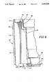
- FIG. 7 is a bottom plan view of the thermoelectric container oriented as shown in FIG. 1.
- FIG. 8 is a rear elevational view of the thermoelectric container oriented as shown in FIG. 1.
- FIG. 9 is a sectional view taken substantially along line 9--9 of FIG. 4.
- FIG. 10 is a sectional view similar to FIG. 9 but showing the handle in an extended position and in the operable position in phantom.
- FIG. 11 is a sectional view taken substantially along line 11--11 of FIG. 10.
- thermoelectric container 20 made in accordance with the concepts of the present invention is indicated generally by the numeral 20 in the drawings and is preferably constructed of a suitable plastic material such as polypropylene.
- Container 20 is shown in a generally horizontal orientation in FIG. 1, and in that orientation, includes a front wall 21, side walls 22 and 23, and a rear wall 24, all extending upwardly from a base surface 25 (which is the bottom surface in this orientation) to form a generally open top which is closeable by means of a cover or door 26 conventionally hinged, as at 27, near the top of rear wall 24.
- Walls 21, 22, 23 and 24 thus form the exterior profile of container 20.
- An inner liner generally indicated by the numeral 28, has a similar profile which includes a front wall 29, side walls 30 and 31, and a rear wall 32, all extending upwardly from a base liner surface 33.
- Liner 28 is inwardly spaced from the exterior profile of container 20.
- wall 21 is spaced from wall 29, side walls 22 and 23 are spaced from side walls 30 and 31, respectively
- rear wall 24 is spaced from rear wall 32
- bottom surface 25 is spaced from bottom liner surface 33.
- the space between these surfaces may be substantially filled with any suitable insulation material to maintain the contents of container 20 hot or cold, as desired.
- An upper peripheral shelf 34 is formed between the top of inner liner 28 and the top of the outer profile of container 20, and preferably is internally formed as part of the liner 28 itself.
- a peripheral rim 35 extends upwardly from shelf 34, at the inner periphery thereof, and is adapted to receive a similarly configured rim 36 extending downwardly from cover 26.
- the upper ends 37 and 38 of side walls 22 and 23, respectively, extend above shelf 34, and when in the closed position (FIG. 3), the lateral edges of cover 26 fit therebetween, thus recessing cover 26 within the profile of side walls 22 and 23.
- a latch 39 of any conventional configuration may be provided on the front edge of cover 26 and received within a recess 40 formed at the top of front wall 21 and in shelf 34.
- FIG. 1 shows handle assemblies 42 in their operating position whereby container 20 may be readily carried
- FIGS. 2 and 4 show them telescopically recessed within interruptions 41 and generally flush with the top of upper ends 37 and 38 of side walls 22 and 23, respectively.
- thermoelectric power module 43 is positioned in front wall 21 and provides for the internal cooling and heating of container 20 in a fashion known to one skilled in the art. Because of the positioning of module 43 in front wall 21, that is, the wall opposite to the wall on which cover 26 is hinged, container 20 can be advantageously positioned in one of two vertical positions, one of which is shown in FIG. 2.
- container 20 is shown as being positioned on side wall 23, which thus becomes its bottom surface in this orientation, with side wall 22 thereby becoming the top wall of container 20, front wall 21 and rear wall 24 becoming its side walls, and bottom 25 becoming its rear wall.
- cover or door 26 now swings with its hinge 27 on a vertical axis along the right hand side of container 20, much like the opening and closing of a refrigerator.
- door 26 is vertically positioned above the ground so that the ground will not interfere therewith upon opening and closing.
- container 20 could be positioned on side wall 22 which would thus become its bottom surface, with side wall 23 becoming the top surface. Door 26 would then swing from the left hand side of container 20 in this vertical orientation.
- module 43 the three described orientations of container 20 are possible. Of course, such orientations would be possible if module 43 were also positioned in back wall 24, but would not be possible if positioned in either side wall 22 or 23 because then container 20 would be suffocating the air intake of module 43 if it were sitting thereon.
- Rear wall 32 of inner liner 28 can also be provided with a plurality of spaced grooves 44 aligned with similar grooves on front wall 29 of liner 28.
- the aligned grooves can act to receive one or more shelves 45 when container 20 is in its two possible vertical orientations, as shown in FIG. 2, or shelves 45 can be used as dividers when container 20 is in the horizontal FIG. 1 position.
- Shelves 45 may be provided with a plurality of vent apertures 46 so as not to inhibit air circulation within container 20.
- Thermoelectric power module 43 is best shown in FIG. 5 as having a generally rectangular body portion which includes generally vertical side walls 47, a generally horizontal top wall 48, and an arcuate front face 49.
- a pedestal 50 extends rearwardly of the body portion. Together, the body portion and pedestal 50 have a common bottom surface 51 (FIG. 7).
- the body portion and pedestal 50 house the components necessary to provide cooling or heating to container 20.
- the specific components involved play no part of the present invention and thus can include the conventional heat exchanger technology, as is well known in the art, wherein air is taken in through module 43 cooled or heated, and then transmitted to the inside of container 20.
- arcuate face 49 is provided with lower air intake vents 52 and upper air exhaust vents 53.
- Decorative ribbing 54 can be provided between vents 52 and 53 to accentuate their presence to the user so that he does not inadvertently position container 20 so as to suffocate vents 52 and 53. Similar vents on the back of module 43 (not shown) communicate with vents 55 and 56 in the front wall 29 of liner 28 so that cooling or warming air is provided internally of container 20.
- Module 43 is preferably intended to operate on a twelve volt, DC source, but could, for example, operate off of other power, such as 24 volts.
- a power cord 57 is permanently molded integrally with module 43 and extends from the bottom of the back thereof.
- Cord 57 preferably carries a plug, generally indicated by the numeral 58, which includes a tip portion 59 suitable for being received in a conventional automotive cigarette lighter.
- tip portion 59 can also be inserted into a conventional AC to DC converter which is plugged into the normal AC household power lines so that container 20 can likewise be used in the home environment.
- Plug 58 is also shown as having a body member 60 with a power selecting switch 61 incorporated therein.
- Switch 61 is electrically coupled to module 43 in a manner as would be known to one skilled in the art so that if it is in one position, module 43 is in a cooling mode and if in the other position, module 43 is in the heating mode.
- two light emitting diodes 62, 63 may be provided in plug body member 60.
- diode 62 for example, may emit a green light indicative that module 43 is in the cooling mode, and diode 63 may emit a red light indicative of the heating mode.
- the user will always be made aware of the current operating mode of module 43, and he will not be inadvertently heating when cooling is desired, or vice versa.
- module 43 is readily removably positioned in front surface 21 of container 20.
- a continuous peripheral rail 64 extends outwardly from walls 47 and wall 48 of module 43.
- Rail 64 is received in a complementary recessed track 65 positioned in the side and upper walls of a recess 66 formed in front wall 21 of container 20.
- wing flanges 67 having apertures 68 therein, extend outwardly from module side walls 47 and from pedestal 50.
- Fasteners 69 may then be positioned through apertures 68 and into the bottom of the side walls of recess 66 to hold module 43 in place.
- module 43 is in need of repair or replacement, only fasteners 69 need be removed and module 43 can be slid out of container 20.
- This arrangement is also advantageous in that module 43 is positioned entirely outside of front liner wall 29 and thus outside of container 20.
- Most prior art thermoelectric units required that the heat exchanging fins protruded to the inside of the unit which, of course, not only prohibited them from being removed, but made cleaning of the container at the area of the unit more difficult.
- a cord routing channel 70 shown as having cord 57 positioned therein, extends from module recess 66 toward the center of bottom surface 25 and terminates at central recessed routing junction 71.
- Cord routing channels 72, 73 and 74 also extend outwardly from junction 71, channel 72 extending toward rear wall 24, channel 73 extending toward side wall 22 and channel 74 extending toward side wall 23.
- Each channel 70, 72, 73 and 74 is provided with one or more cord gripping assemblies 75 which, when cord 57 is pushed into a channel 70, 72, 73 or 74, will hold cord 57 securely within that channel.
- Cord 57 can thus be held flush with bottom surface 25 or possibly slightly therebelow.
- bottom feet 76 can be provided near each corner of bottom surface 25 to raise container 20 off of the floor when in the horizontal FIG. 1 position, or maintain container 20 away from a wall which it might be positioned adjacent thereto when in the vertical position such as shown in FIG. 2.
- Routing channels 70, 72, 73 and 74 thus permit cord 57 to be most conveniently directed to its desired termination point.
- cord 57 is routed from module 43 through channel 70 to junction 71 whereat it may be turned and routed through channel 74 to pass through the bottom of side wall 23.
- Container 20 also includes means by which cord 57 may be conveniently stored therein when container 20 is not in use or when it is being transported. Such is shown in FIGS. 7 and 8 and includes a storage recess 77 formed in the bottom surface 25 and rear wall 24 of container 20. Two dove-tail slots 78 extend upwardly within the inner wall 79 of recess 77 from bottom surface 25. Slots 78 are adapted to receive complementary shaped lugs 80 having pegs 81 extending generally laterally therefrom. When container 20 is not in use, cord 57 may be routed through channel 72 and into recess 77 to be wound around pegs 81 to thereby maintain cord 57 out-of-the-way within recess 77.
- handle assemblies 42 The preferred construction of handle assemblies 42 and the manner in which they can be recessed within container 20 are best shown with reference to FIGS. 9-11.
- container 20 is preferably provided with two handle assemblies positioned near the top of side walls 22 and 23 and their associated liner side walls 30 and 31.
- Each handle assembly 42 includes a relatively U-shaped handle having a gripping portion 82 and arms 83 extending inwardly from the ends thereof. As shown in FIG. 11, the inner end of each arm 83 is axially split, as at 84, thereby forming tine ends 85.
- each tine end 85 is provided with generally circular embossments 86 which are spaced from tine ends 85 by hubs 87 of a slightly lesser diameter than embossments 86 thereby forming a slot opening 88 between the top of embossments 86 and tine ends 85.
- Handle assemblies 42 are positioned within interruption 41 of upper ends 37 and 38 of side walls 22 and 23 respectively.
- a flat shelf 89 is formed having pockets 90 therein within which the inner ends of handle arms 83 are received when the handles are in their operating position as shown in FIG. 1.
- the bottom of pockets 90 are open, as at 91, into the space between the liner walls 30 and 31 and side walls 22 and 23, respectively, thereby forming lower ledges 92.
- the opening 91 is of a lesser size than the distance between the outer edges of embossments 86 on tine ends 85.
- tine ends 85 are squeezed together permitting the lower ends of arms 83 to pass through opening 91 whereupon tine ends 85 will spread apart and the handle will drop until gripping portion 82 is resting on shelf 89, the position shown, for example, in FIGS. 2, 8 and 9.
- Arms 83 are thus positioned within lower pockets 93 formed between side walls 22 and 23 and liner side walls 30 and 31, respectively. Pockets 93 not only serve the purpose of isolating handle arms 83 from the insulation received therein, but also prevent the insulation from coming out through openings 91.
- container 20 may be fully insulated around the handles, leaving no voids therein as may be found in the prior art, thereby providing a more thermally efficient unit.
- gripping portion 82 thereof When it is desired to utilize the handles for carrying container 20, gripping portion 82 thereof is merely lifted from the FIG. 9 to the FIG. 10 solid line position. However, they cannot be totally removed back through opening 91 because, as best shown in FIG. 11, slot openings 88 between embossments 86 and tine ends 85 engage lower ledges 92 at the bottom edge of opening 91 to limit the permissible amount of upward movement of the handles.
- the handles can then be rotated 90. to the phantom line position of FIG. 10, and as also shown in FIG. 1, so that container 20 can be readily transported.
- a plug member 94 may be inserted into the split 84 which forms tine ends 85.
- FIG. 11 shows one plug member 94 in place, it being understood that both arms 83 are preferably provided with a plug member 94.
- Each plug member has opposed slots (not shown) therein which may be guided upwardly on tracks 95 formed on the inside of tine ends 85.
- Pointed lugs 96 extend outwardly from each plug member 94 to engage a complementary shaped recess 97 formed on the inside of tine ends 85 adjacent tracks 95. When plug members 94 are fully inserted, lugs 96 snap into recess 97 to assure that tine ends 85 are spread sufficiently to assure their positioning within pockets 90.
- thermoelectric container constructed in accordance with the concepts of the present invention, as described herein, accomplishes the objects of the present invention and otherwise substantially improves the art.
Abstract
Description
Claims (78)
Priority Applications (5)
| Application Number | Priority Date | Filing Date | Title |
|---|---|---|---|
| US07/930,009 US5301508A (en) | 1992-08-14 | 1992-08-14 | Thermoelectric portable container |
| JP5220539A JPH0716162A (en) | 1992-08-14 | 1993-08-13 | Thermoelectric type container |
| KR1019930015683A KR940003522A (en) | 1992-08-14 | 1993-08-13 | Thermoelectric container |
| CA002104131A CA2104131A1 (en) | 1992-08-14 | 1993-08-13 | Thermoelectric container |
| BR9303382A BR9303382A (en) | 1992-08-14 | 1993-08-13 | THERMO ELECTRIC CONTAINER |
Applications Claiming Priority (1)
| Application Number | Priority Date | Filing Date | Title |
|---|---|---|---|
| US07/930,009 US5301508A (en) | 1992-08-14 | 1992-08-14 | Thermoelectric portable container |
Publications (1)
| Publication Number | Publication Date |
|---|---|
| US5301508A true US5301508A (en) | 1994-04-12 |
Family
ID=25458827
Family Applications (1)
| Application Number | Title | Priority Date | Filing Date |
|---|---|---|---|
| US07/930,009 Expired - Fee Related US5301508A (en) | 1992-08-14 | 1992-08-14 | Thermoelectric portable container |
Country Status (5)
| Country | Link |
|---|---|
| US (1) | US5301508A (en) |
| JP (1) | JPH0716162A (en) |
| KR (1) | KR940003522A (en) |
| BR (1) | BR9303382A (en) |
| CA (1) | CA2104131A1 (en) |
Cited By (70)
| Publication number | Priority date | Publication date | Assignee | Title |
|---|---|---|---|---|
| WO1996007063A1 (en) * | 1994-08-26 | 1996-03-07 | Barbara Paechter | Small luggage item with cooling unit |
| US5501076A (en) * | 1993-04-14 | 1996-03-26 | Marlow Industries, Inc. | Compact thermoelectric refrigerator and module |
| US5572872A (en) * | 1994-08-15 | 1996-11-12 | Hlavacek; Robert A. | Liquid cooling, storing and dispensing device |
| US5605047A (en) * | 1994-01-12 | 1997-02-25 | Owens-Corning Fiberglas Corp. | Enclosure for thermoelectric refrigerator and method |
| US5634343A (en) * | 1994-01-24 | 1997-06-03 | Alko Group, Ltd. | Beverage cooling dispenser |
| WO1997047931A1 (en) * | 1996-06-11 | 1997-12-18 | Atoma International Inc. | Device for heating and cooling a beverage |
| USD388282S (en) * | 1996-11-04 | 1997-12-30 | Rubbermaid Specialty Products Inc. | Lid for ice chest |
| US5860281A (en) * | 1997-02-14 | 1999-01-19 | Igloo Products Corporation | Thermoelectric cooler and warmer for food with table top tray |
| US5941077A (en) * | 1998-12-21 | 1999-08-24 | Safyan; Bernard | Chill-hot buffet serving tray |
| US6021642A (en) * | 1998-06-24 | 2000-02-08 | Guinn; Bernadette | Cosmetic storage and refrigeration unit |
| GB2339895A (en) * | 1998-07-22 | 2000-02-09 | Kenneth John Stout | A portable compartment for an automated guided vehicle (AGV) |
| USD420860S (en) * | 1999-05-18 | 2000-02-22 | Rubbermaid Commercial Products Llc | Insulated container |
| US6032481A (en) * | 1997-08-26 | 2000-03-07 | Mosby; Sharon D. | Thermoregulating container |
| US6094917A (en) * | 1998-12-09 | 2000-08-01 | Sundhar; Shaam P | Thermo electric humidor |
| EP1152199A1 (en) * | 2000-05-03 | 2001-11-07 | IPV Inheidener Produktions- und Vertriebsgesellschaft mbH | Thermal container |
| US20020000918A1 (en) * | 2000-07-03 | 2002-01-03 | Hunter Rick C. | Advanced thermal container |
| GB2371677A (en) * | 2000-09-08 | 2002-07-31 | Distinctive Appliances Inc | Temperature controlled compartment apparatus with thermoelectric module |
| US6449958B1 (en) | 2000-08-18 | 2002-09-17 | Matthew R. Foye | Contained beverage cooling apparatus |
| US6484512B1 (en) | 2001-06-08 | 2002-11-26 | Maytag Corporation | Thermoelectric temperature controlled drawer assembly |
| US6580025B2 (en) | 2001-08-03 | 2003-06-17 | The Boeing Company | Apparatus and methods for thermoelectric heating and cooling |
| US20030137828A1 (en) * | 2002-01-10 | 2003-07-24 | Artak Ter-Hovhannisian | Low temperature led lighting system |
| US6612116B2 (en) | 1999-02-26 | 2003-09-02 | Maytag Corporation | Thermoelectric temperature controlled refrigerator food storage compartment |
| US6658857B1 (en) * | 2003-02-20 | 2003-12-09 | Hatho M. George | Portable thermoelectric cooling and heating appliance device and method of using |
| US6666032B1 (en) * | 1999-07-01 | 2003-12-23 | Kryotrans Limited | Thermally insulated container |
| US6693260B1 (en) * | 2001-06-04 | 2004-02-17 | Spacessories Inc. | Warming apparatus |
| GB2401168A (en) * | 2003-04-30 | 2004-11-03 | Dometic Sarl | Refrigeration system |
| US20050081558A1 (en) * | 2003-10-21 | 2005-04-21 | Twinbird Corporation | Portable container |
| US20050082046A1 (en) * | 2003-10-20 | 2005-04-21 | Kitchens Mark C. | Structural support apparatus with active or passive heat transfer system |
| US6889513B1 (en) | 2004-02-19 | 2005-05-10 | Clark Distribution Inc. | Temperature control system for nitrous oxide pressurized bottle |
| FR2870929A1 (en) * | 2004-05-25 | 2005-12-02 | Coleman Co | PORTABLE REFRIGERATED ISOTHERMAL CONTAINER |
| US20050274118A1 (en) * | 2004-05-26 | 2005-12-15 | Ardiem Medical, Inc. | Apparatus and method for inducing emergency hypothermia |
| US20060175355A1 (en) * | 2005-02-09 | 2006-08-10 | Glucksman Dov Z | Beverage dispenser |
| US7122763B1 (en) * | 2005-08-01 | 2006-10-17 | J Sheng Co., Ltd. | Thermos bag |
| US20070119187A1 (en) * | 2005-11-30 | 2007-05-31 | Kitchens Mark C | Thermoelectric unibody cooler apparatus |
| US20070119186A1 (en) * | 2005-11-30 | 2007-05-31 | Kitchens Mark C | Universal thermoelectric module apparatus |
| US20100115969A1 (en) * | 2008-11-12 | 2010-05-13 | General Mills, Inc. | Portable thermoelectric cooling/heating unit and related merchandizing system |
| US20100264048A1 (en) * | 2009-04-16 | 2010-10-21 | Gabriel Sharkey Gunsberg | Temperature-controlled musical instrument carrying case |
| US20100275615A1 (en) * | 2006-12-08 | 2010-11-04 | Rico Francois | Electrical lunch box |
| US7975881B1 (en) | 2005-02-09 | 2011-07-12 | Appliance Development Corporation | Beverage dispenser |
| WO2011123645A2 (en) | 2010-03-31 | 2011-10-06 | Pharmasset, Inc. | Nucleoside phosphoramidates |
| WO2011123672A1 (en) | 2010-03-31 | 2011-10-06 | Pharmasset, Inc. | Purine nucleoside phosphoramidate |
| US8065889B1 (en) * | 2008-09-26 | 2011-11-29 | Silberman Louis Z | Adjustable support structure and drainage system for portable ice chest |
| US8104295B2 (en) | 2006-01-30 | 2012-01-31 | Amerigon Incorporated | Cooling system for container in a vehicle |
| US20120125016A1 (en) * | 2009-08-04 | 2012-05-24 | Cline William A | Dual functional temperature control system applicator system |
| EP2508044A1 (en) * | 2009-12-02 | 2012-10-10 | Jimmy Quang Viet Doan | Portable appliance for heating and cooling food |
| US20130284619A1 (en) * | 2012-04-25 | 2013-10-31 | Jeffry A. Daley | Divider and Cutting Board |
| US8978392B2 (en) | 2005-08-04 | 2015-03-17 | Eic Solutions, Inc. | Thermoelectrically air conditioned transit case |
| US9220364B1 (en) | 2012-09-27 | 2015-12-29 | Hot Shot USA LLC | System and methods for dispensing hot beverages |
| US9445524B2 (en) | 2012-07-06 | 2016-09-13 | Gentherm Incorporated | Systems and methods for thermoelectrically cooling inductive charging stations |
| NO20150501A1 (en) * | 2015-04-24 | 2016-10-25 | Norsk Vannkjoeling As | Modular beverage cooler. |
| US20170215643A1 (en) * | 2016-01-28 | 2017-08-03 | Pearl Beach | Portable temperature regulating food conveying device |
| EP3222628A1 (en) | 2008-12-23 | 2017-09-27 | Gilead Pharmasset LLC | Nucleoside phosphoramidates |
| US20170343247A1 (en) * | 2016-05-26 | 2017-11-30 | Mohammad Sharaz Ahmad | Self-ice making / self heating hybrid food and beverage storage chest |
| US20180289533A1 (en) * | 2017-02-02 | 2018-10-11 | Robert W. Johnson | Therapeutic Eye Pod System |
| WO2019071112A1 (en) * | 2017-10-06 | 2019-04-11 | Carrier Corporation | Responsive cooling based on external factors |
| WO2019121908A1 (en) * | 2017-12-19 | 2019-06-27 | Tec4Med Lifescience Gmbh | Air-conditioning container |
| CN110398107A (en) * | 2019-08-28 | 2019-11-01 | 广东富信科技股份有限公司 | Breast milk cold storage plant and liner |
| USD901986S1 (en) * | 2018-04-12 | 2020-11-17 | Dometic Sweden Ab | Cooler |
| US20210055030A1 (en) * | 2018-04-25 | 2021-02-25 | Leisure-Tec International Limited | Mobile refrigerator having built-in handles |
| USD935280S1 (en) * | 2019-11-04 | 2021-11-09 | Dometic Sweden Ab | Cover for a cooler |
| US11257311B1 (en) * | 2020-10-28 | 2022-02-22 | Benjamin Carpenter | Locking cooler assembly |
| USD953814S1 (en) * | 2019-11-04 | 2022-06-07 | Dometic Sweden Ab | Cover for a cooler |
| USD954764S1 (en) | 2019-01-04 | 2022-06-14 | Dometic Sweden A.B | Cooler fender frame |
| US11359848B2 (en) | 2019-01-04 | 2022-06-14 | Dometic Sweden Ab | Mobile cooling box with ice maker |
| US11396406B2 (en) | 2019-01-04 | 2022-07-26 | Dometic Sweden Ab | Mobile cooling box with hinge module |
| US11415355B2 (en) | 2019-01-04 | 2022-08-16 | Dometic Sweden Ab | Mobile cooling box with handle module |
| CN116513479A (en) * | 2023-04-25 | 2023-08-01 | 东莞市雄大机械有限公司 | Rotor wing repairing and heating device |
| US11821672B2 (en) | 2019-01-04 | 2023-11-21 | Dometic Sweden Ab | Mobile cooling box with air vents |
| EP4282482A2 (en) | 2007-03-30 | 2023-11-29 | Gilead Sciences, Inc. | Nucleoside phosphoramidate prodrugs |
| US11913713B2 (en) | 2019-01-04 | 2024-02-27 | Dometic Sweden Ab | Mobile cooling box with latch handle opening |
Families Citing this family (2)
| Publication number | Priority date | Publication date | Assignee | Title |
|---|---|---|---|---|
| JP6667290B2 (en) * | 2015-12-25 | 2020-03-18 | シャープ株式会社 | container |
| CN107826484A (en) * | 2017-10-21 | 2018-03-23 | 佛山北瓜科技有限公司 | A kind of portable temperature control medical kit |
Citations (12)
| Publication number | Priority date | Publication date | Assignee | Title |
|---|---|---|---|---|
| US2874205A (en) * | 1955-11-03 | 1959-02-17 | Motorola Inc | Electrical connector |
| US3111166A (en) * | 1961-04-13 | 1963-11-19 | Gen Electric | Portable heating and cooling appliance |
| US3194023A (en) * | 1963-03-20 | 1965-07-13 | Gustav H Sudmeier | Thermo-electric refrigerator unit |
| US4089184A (en) * | 1976-07-26 | 1978-05-16 | Bipol Ltd. | Hand case |
| US4107934A (en) * | 1976-07-26 | 1978-08-22 | Bipol Ltd. | Portable refrigerator unit |
| US4274262A (en) * | 1980-03-21 | 1981-06-23 | Koolatron Industries, Limited | Thermoelectric jug cooler and control circuit |
| US4297850A (en) * | 1979-12-26 | 1981-11-03 | Koolatron Industries, Inc. | Wall mounted thermoelectric refrigerator |
| US4326383A (en) * | 1980-08-04 | 1982-04-27 | Koolatron Industries, Ltd. | Compact thermoelectric refrigerator |
| US4346562A (en) * | 1980-12-18 | 1982-08-31 | Bipol Ltd. | Thermoelectric device and process for making the same |
| US4759190A (en) * | 1987-04-22 | 1988-07-26 | Leonard Trachtenberg | Vehicle thermoelectric cooling and heating food and drink appliance |
| US4981019A (en) * | 1989-11-14 | 1991-01-01 | Hicks Carole L | Solar powered portable food container |
| US5060479A (en) * | 1989-11-03 | 1991-10-29 | Afikim Kvutzat Poalim Lehity Ashvut Shitufit B.M. | Thermoelectric device for heating or cooling food and drink containers |
-
1992
- 1992-08-14 US US07/930,009 patent/US5301508A/en not_active Expired - Fee Related
-
1993
- 1993-08-13 BR BR9303382A patent/BR9303382A/en unknown
- 1993-08-13 JP JP5220539A patent/JPH0716162A/en active Pending
- 1993-08-13 CA CA002104131A patent/CA2104131A1/en not_active Abandoned
- 1993-08-13 KR KR1019930015683A patent/KR940003522A/en not_active Application Discontinuation
Patent Citations (12)
| Publication number | Priority date | Publication date | Assignee | Title |
|---|---|---|---|---|
| US2874205A (en) * | 1955-11-03 | 1959-02-17 | Motorola Inc | Electrical connector |
| US3111166A (en) * | 1961-04-13 | 1963-11-19 | Gen Electric | Portable heating and cooling appliance |
| US3194023A (en) * | 1963-03-20 | 1965-07-13 | Gustav H Sudmeier | Thermo-electric refrigerator unit |
| US4089184A (en) * | 1976-07-26 | 1978-05-16 | Bipol Ltd. | Hand case |
| US4107934A (en) * | 1976-07-26 | 1978-08-22 | Bipol Ltd. | Portable refrigerator unit |
| US4297850A (en) * | 1979-12-26 | 1981-11-03 | Koolatron Industries, Inc. | Wall mounted thermoelectric refrigerator |
| US4274262A (en) * | 1980-03-21 | 1981-06-23 | Koolatron Industries, Limited | Thermoelectric jug cooler and control circuit |
| US4326383A (en) * | 1980-08-04 | 1982-04-27 | Koolatron Industries, Ltd. | Compact thermoelectric refrigerator |
| US4346562A (en) * | 1980-12-18 | 1982-08-31 | Bipol Ltd. | Thermoelectric device and process for making the same |
| US4759190A (en) * | 1987-04-22 | 1988-07-26 | Leonard Trachtenberg | Vehicle thermoelectric cooling and heating food and drink appliance |
| US5060479A (en) * | 1989-11-03 | 1991-10-29 | Afikim Kvutzat Poalim Lehity Ashvut Shitufit B.M. | Thermoelectric device for heating or cooling food and drink containers |
| US4981019A (en) * | 1989-11-14 | 1991-01-01 | Hicks Carole L | Solar powered portable food container |
Non-Patent Citations (6)
| Title |
|---|
| "Tropicool" brochure (6 pp.), 1991, WAECO-Wahning & Co. GmbH, D-4407 Emsdetten, Postfach 11 44, Sinninger Strasse 36. |
| 1991 Coleman Outdoor Products, Inc., The Coleman Company, Inc. 250 North St. Francis, Wichita, Kans. 67202, pp. 37 39. * |
| 1991 Coleman Outdoor Products, Inc., The Coleman Company, Inc. 250 North St. Francis, Wichita, Kans. 67202, pp. 37-39. |
| Igloo 1992 Product Catalog and Price List, Igloo Products Corp., P.O. Box 19322, Houston, Tex. 77224 9322, pp. 2 3. * |
| Igloo® 1992 Product Catalog and Price List, Igloo Products Corp., P.O. Box 19322, Houston, Tex. 77224-9322, pp. 2-3. |
| Tropicool brochure (6 pp.), 1991, WAECO W hning & Co. GmbH, D 4407 Emsdetten, Postfach 11 44, Sinninger Strasse 36. * |
Cited By (102)
| Publication number | Priority date | Publication date | Assignee | Title |
|---|---|---|---|---|
| US5501076A (en) * | 1993-04-14 | 1996-03-26 | Marlow Industries, Inc. | Compact thermoelectric refrigerator and module |
| US5605047A (en) * | 1994-01-12 | 1997-02-25 | Owens-Corning Fiberglas Corp. | Enclosure for thermoelectric refrigerator and method |
| US5634343A (en) * | 1994-01-24 | 1997-06-03 | Alko Group, Ltd. | Beverage cooling dispenser |
| US5572872A (en) * | 1994-08-15 | 1996-11-12 | Hlavacek; Robert A. | Liquid cooling, storing and dispensing device |
| WO1996007063A1 (en) * | 1994-08-26 | 1996-03-07 | Barbara Paechter | Small luggage item with cooling unit |
| WO1997047931A1 (en) * | 1996-06-11 | 1997-12-18 | Atoma International Inc. | Device for heating and cooling a beverage |
| US5720171A (en) * | 1996-06-11 | 1998-02-24 | Atoma International, Inc. | Device for heating and cooling a beverage |
| USD388282S (en) * | 1996-11-04 | 1997-12-30 | Rubbermaid Specialty Products Inc. | Lid for ice chest |
| US6026647A (en) * | 1997-02-14 | 2000-02-22 | Igloo Products Corporation | Thermoelectric cooler and warmer for food with table top tray |
| US5860281A (en) * | 1997-02-14 | 1999-01-19 | Igloo Products Corporation | Thermoelectric cooler and warmer for food with table top tray |
| US6301901B1 (en) | 1997-02-14 | 2001-10-16 | Igloo Products Corporation | Thermoelectric cooler and warmer for food with table top tray |
| US6032481A (en) * | 1997-08-26 | 2000-03-07 | Mosby; Sharon D. | Thermoregulating container |
| US6021642A (en) * | 1998-06-24 | 2000-02-08 | Guinn; Bernadette | Cosmetic storage and refrigeration unit |
| GB2339895A (en) * | 1998-07-22 | 2000-02-09 | Kenneth John Stout | A portable compartment for an automated guided vehicle (AGV) |
| US6094917A (en) * | 1998-12-09 | 2000-08-01 | Sundhar; Shaam P | Thermo electric humidor |
| US5941077A (en) * | 1998-12-21 | 1999-08-24 | Safyan; Bernard | Chill-hot buffet serving tray |
| US6612116B2 (en) | 1999-02-26 | 2003-09-02 | Maytag Corporation | Thermoelectric temperature controlled refrigerator food storage compartment |
| USD420860S (en) * | 1999-05-18 | 2000-02-22 | Rubbermaid Commercial Products Llc | Insulated container |
| US6666032B1 (en) * | 1999-07-01 | 2003-12-23 | Kryotrans Limited | Thermally insulated container |
| EP1152199A1 (en) * | 2000-05-03 | 2001-11-07 | IPV Inheidener Produktions- und Vertriebsgesellschaft mbH | Thermal container |
| US20020000918A1 (en) * | 2000-07-03 | 2002-01-03 | Hunter Rick C. | Advanced thermal container |
| US6771183B2 (en) * | 2000-07-03 | 2004-08-03 | Kodiak Technologies, Inc. | Advanced thermal container |
| US6449958B1 (en) | 2000-08-18 | 2002-09-17 | Matthew R. Foye | Contained beverage cooling apparatus |
| GB2371677A (en) * | 2000-09-08 | 2002-07-31 | Distinctive Appliances Inc | Temperature controlled compartment apparatus with thermoelectric module |
| US6693260B1 (en) * | 2001-06-04 | 2004-02-17 | Spacessories Inc. | Warming apparatus |
| US6484512B1 (en) | 2001-06-08 | 2002-11-26 | Maytag Corporation | Thermoelectric temperature controlled drawer assembly |
| US6580025B2 (en) | 2001-08-03 | 2003-06-17 | The Boeing Company | Apparatus and methods for thermoelectric heating and cooling |
| US20030137828A1 (en) * | 2002-01-10 | 2003-07-24 | Artak Ter-Hovhannisian | Low temperature led lighting system |
| US7121675B2 (en) * | 2002-01-10 | 2006-10-17 | Artak Ter-Hovhannisian | Low temperature LED lighting system |
| US6658857B1 (en) * | 2003-02-20 | 2003-12-09 | Hatho M. George | Portable thermoelectric cooling and heating appliance device and method of using |
| GB2401168A (en) * | 2003-04-30 | 2004-11-03 | Dometic Sarl | Refrigeration system |
| US20050082046A1 (en) * | 2003-10-20 | 2005-04-21 | Kitchens Mark C. | Structural support apparatus with active or passive heat transfer system |
| US7007747B2 (en) * | 2003-10-20 | 2006-03-07 | Mark Charles Kitchens | Structural support apparatus with active or passive heat transfer system |
| US6964179B2 (en) * | 2003-10-21 | 2005-11-15 | Twinbird Corporation | Portable container |
| US20050081558A1 (en) * | 2003-10-21 | 2005-04-21 | Twinbird Corporation | Portable container |
| EP1526347A1 (en) * | 2003-10-21 | 2005-04-27 | Twinbird Corporation | Portable container |
| US6889513B1 (en) | 2004-02-19 | 2005-05-10 | Clark Distribution Inc. | Temperature control system for nitrous oxide pressurized bottle |
| FR2870929A1 (en) * | 2004-05-25 | 2005-12-02 | Coleman Co | PORTABLE REFRIGERATED ISOTHERMAL CONTAINER |
| US7231771B2 (en) * | 2004-05-26 | 2007-06-19 | Ardiem Medical, Inc. | Apparatus and method for inducing emergency hypothermia |
| US20050274118A1 (en) * | 2004-05-26 | 2005-12-15 | Ardiem Medical, Inc. | Apparatus and method for inducing emergency hypothermia |
| US20060175355A1 (en) * | 2005-02-09 | 2006-08-10 | Glucksman Dov Z | Beverage dispenser |
| US7975881B1 (en) | 2005-02-09 | 2011-07-12 | Appliance Development Corporation | Beverage dispenser |
| US7122763B1 (en) * | 2005-08-01 | 2006-10-17 | J Sheng Co., Ltd. | Thermos bag |
| US8978392B2 (en) | 2005-08-04 | 2015-03-17 | Eic Solutions, Inc. | Thermoelectrically air conditioned transit case |
| US20070119187A1 (en) * | 2005-11-30 | 2007-05-31 | Kitchens Mark C | Thermoelectric unibody cooler apparatus |
| US20070119186A1 (en) * | 2005-11-30 | 2007-05-31 | Kitchens Mark C | Universal thermoelectric module apparatus |
| US8104295B2 (en) | 2006-01-30 | 2012-01-31 | Amerigon Incorporated | Cooling system for container in a vehicle |
| US8438863B2 (en) | 2006-01-30 | 2013-05-14 | Gentherm Incorporated | Climate controlled beverage container |
| US20100275615A1 (en) * | 2006-12-08 | 2010-11-04 | Rico Francois | Electrical lunch box |
| EP4282482A2 (en) | 2007-03-30 | 2023-11-29 | Gilead Sciences, Inc. | Nucleoside phosphoramidate prodrugs |
| US8065889B1 (en) * | 2008-09-26 | 2011-11-29 | Silberman Louis Z | Adjustable support structure and drainage system for portable ice chest |
| WO2010056565A1 (en) * | 2008-11-12 | 2010-05-20 | General Mills, Inc. | Portable thermoelectric cooling/heating unit and related merchandizing system |
| US20100115969A1 (en) * | 2008-11-12 | 2010-05-13 | General Mills, Inc. | Portable thermoelectric cooling/heating unit and related merchandizing system |
| US8468836B2 (en) * | 2008-11-12 | 2013-06-25 | General Mills, Inc. | Portable thermoelectric cooling/heating unit and related merchandizing system |
| EP3222628A1 (en) | 2008-12-23 | 2017-09-27 | Gilead Pharmasset LLC | Nucleoside phosphoramidates |
| US20100264048A1 (en) * | 2009-04-16 | 2010-10-21 | Gabriel Sharkey Gunsberg | Temperature-controlled musical instrument carrying case |
| US20120125016A1 (en) * | 2009-08-04 | 2012-05-24 | Cline William A | Dual functional temperature control system applicator system |
| US9733654B2 (en) * | 2009-08-04 | 2017-08-15 | William A. Cline | Dual functional temperature control system applicator system |
| EP2508044A1 (en) * | 2009-12-02 | 2012-10-10 | Jimmy Quang Viet Doan | Portable appliance for heating and cooling food |
| EP2508044A4 (en) * | 2009-12-02 | 2015-03-25 | Oxx Products Llc | Portable appliance for heating and cooling food |
| WO2011123668A2 (en) | 2010-03-31 | 2011-10-06 | Pharmasset, Inc. | Stereoselective synthesis of phosphorus containing actives |
| EP3290428A1 (en) | 2010-03-31 | 2018-03-07 | Gilead Pharmasset LLC | Tablet comprising crystalline (s)-isopropyl 2-(((s)-(((2r,3r,4r,5r)-5-(2,4-dioxo-3,4-dihydropyrimidin-1 (2h)-yl)-4-fluoro-3-hydroxy-4-methyltetrahydrofuran-2-yl)methoxy)(phenoxy)phosphoryl)amino)propanoate |
| WO2011123645A2 (en) | 2010-03-31 | 2011-10-06 | Pharmasset, Inc. | Nucleoside phosphoramidates |
| WO2011123672A1 (en) | 2010-03-31 | 2011-10-06 | Pharmasset, Inc. | Purine nucleoside phosphoramidate |
| EP2752422A1 (en) | 2010-03-31 | 2014-07-09 | Gilead Pharmasset LLC | Stereoselective synthesis of phosphorus containing actives |
| US20130284619A1 (en) * | 2012-04-25 | 2013-10-31 | Jeffry A. Daley | Divider and Cutting Board |
| US9108790B2 (en) * | 2012-04-25 | 2015-08-18 | Jeffry A. Daley | Divider and cutting board |
| US9445524B2 (en) | 2012-07-06 | 2016-09-13 | Gentherm Incorporated | Systems and methods for thermoelectrically cooling inductive charging stations |
| US10455728B2 (en) | 2012-07-06 | 2019-10-22 | Gentherm Incorporated | Systems and methods for thermoelectrically cooling inductive charging stations |
| US9451723B2 (en) | 2012-07-06 | 2016-09-20 | Gentherm Incorporated | System and method for thermoelectrically cooling inductive charging assemblies |
| US9861006B2 (en) | 2012-07-06 | 2018-01-02 | Gentherm Incorporated | Systems and methods for thermoelectrically cooling inductive charging stations |
| US10219407B2 (en) | 2012-07-06 | 2019-02-26 | Gentherm Incorporated | Systems and methods for cooling inductive charging assemblies |
| US10123649B2 (en) | 2012-09-27 | 2018-11-13 | Hotshot USA LLC | System and methods for dispensing hot beverages |
| US9220364B1 (en) | 2012-09-27 | 2015-12-29 | Hot Shot USA LLC | System and methods for dispensing hot beverages |
| NO20150501A1 (en) * | 2015-04-24 | 2016-10-25 | Norsk Vannkjoeling As | Modular beverage cooler. |
| US20170215643A1 (en) * | 2016-01-28 | 2017-08-03 | Pearl Beach | Portable temperature regulating food conveying device |
| US20170343247A1 (en) * | 2016-05-26 | 2017-11-30 | Mohammad Sharaz Ahmad | Self-ice making / self heating hybrid food and beverage storage chest |
| US11125474B2 (en) * | 2016-05-26 | 2021-09-21 | Mohammad Sharaz Ahmad | Self-ice making / self heating hybrid food and beverage storage chest |
| US20180289533A1 (en) * | 2017-02-02 | 2018-10-11 | Robert W. Johnson | Therapeutic Eye Pod System |
| US10835415B2 (en) * | 2017-02-02 | 2020-11-17 | Robert W. Johnson | Therapeutic eye pod system |
| WO2019071112A1 (en) * | 2017-10-06 | 2019-04-11 | Carrier Corporation | Responsive cooling based on external factors |
| US11530849B2 (en) | 2017-10-06 | 2022-12-20 | Carrier Corporation | Responsive cooling based on external factors |
| EP3578890A1 (en) * | 2017-12-19 | 2019-12-11 | Tec4med Lifescience GmbH | Air conditioning container |
| LU100583B1 (en) * | 2017-12-19 | 2019-07-25 | Tec4Med Lifescience Gmbh | Klimatisierbehälter |
| WO2019121908A1 (en) * | 2017-12-19 | 2019-06-27 | Tec4Med Lifescience Gmbh | Air-conditioning container |
| USD921439S1 (en) * | 2018-04-12 | 2021-06-08 | Dometic Sweden Ab | Cooler |
| USD901986S1 (en) * | 2018-04-12 | 2020-11-17 | Dometic Sweden Ab | Cooler |
| US20210055030A1 (en) * | 2018-04-25 | 2021-02-25 | Leisure-Tec International Limited | Mobile refrigerator having built-in handles |
| US11396406B2 (en) | 2019-01-04 | 2022-07-26 | Dometic Sweden Ab | Mobile cooling box with hinge module |
| US11913713B2 (en) | 2019-01-04 | 2024-02-27 | Dometic Sweden Ab | Mobile cooling box with latch handle opening |
| USD954764S1 (en) | 2019-01-04 | 2022-06-14 | Dometic Sweden A.B | Cooler fender frame |
| US11359848B2 (en) | 2019-01-04 | 2022-06-14 | Dometic Sweden Ab | Mobile cooling box with ice maker |
| US11827423B2 (en) | 2019-01-04 | 2023-11-28 | Dometic Sweden Ab | Mobile cooling box with hinge module |
| US11415355B2 (en) | 2019-01-04 | 2022-08-16 | Dometic Sweden Ab | Mobile cooling box with handle module |
| USD1023684S1 (en) | 2019-01-04 | 2024-04-23 | Dometic Sweden Ab | Fender frame of a cooler |
| US11754332B2 (en) | 2019-01-04 | 2023-09-12 | Dometic Sweden Ab | Mobile cooling box with ice maker |
| US11821672B2 (en) | 2019-01-04 | 2023-11-21 | Dometic Sweden Ab | Mobile cooling box with air vents |
| CN110398107A (en) * | 2019-08-28 | 2019-11-01 | 广东富信科技股份有限公司 | Breast milk cold storage plant and liner |
| USD935280S1 (en) * | 2019-11-04 | 2021-11-09 | Dometic Sweden Ab | Cover for a cooler |
| USD953814S1 (en) * | 2019-11-04 | 2022-06-07 | Dometic Sweden Ab | Cover for a cooler |
| US11257311B1 (en) * | 2020-10-28 | 2022-02-22 | Benjamin Carpenter | Locking cooler assembly |
| CN116513479A (en) * | 2023-04-25 | 2023-08-01 | 东莞市雄大机械有限公司 | Rotor wing repairing and heating device |
Also Published As
| Publication number | Publication date |
|---|---|
| JPH0716162A (en) | 1995-01-20 |
| CA2104131A1 (en) | 1994-02-15 |
| KR940003522A (en) | 1994-03-12 |
| BR9303382A (en) | 1994-03-15 |
Similar Documents
| Publication | Publication Date | Title |
|---|---|---|
| US5301508A (en) | Thermoelectric portable container | |
| US11619378B2 (en) | Container apparatus and method of using same | |
| US6034355A (en) | Meal delivery system | |
| US5319937A (en) | Thermoelectric cooler and warmer | |
| US11964378B2 (en) | Job box | |
| EP0413729B1 (en) | Vehicle thermoelectric cooling and heating food and drink appliance | |
| US4759190A (en) | Vehicle thermoelectric cooling and heating food and drink appliance | |
| US4904848A (en) | Portable cooling and heating device | |
| EP0426092A1 (en) | A thermoelectric device for heating or cooling food and drink containers | |
| US4543471A (en) | Controlled temperature food carrier | |
| US10107547B1 (en) | Combined thermoelectric cooler and bottle warmer and methods thereof | |
| ES2234254T3 (en) | FOOD DISTRIBUTION BOX. | |
| US7102103B2 (en) | Banquet cart including heat retention material | |
| US20200316486A1 (en) | Consolidated Pit Stand and Caddy for Remote-Controlled Hobby Vehicles | |
| AU2019225392B2 (en) | A compact kitchen assembly | |
| CA1306511C (en) | Vehicle thermoelectric cooling and heating food and drink appliance | |
| KR950004534Y1 (en) | Ice box | |
| JP3081790U (en) | Table warmer | |
| JPH06265253A (en) | Cold/hot refrigerator | |
| JP2022151380A (en) | Home delivery mobile vehicle | |
| JPS61231376A (en) | Simple type cold-insulating warehouse | |
| JPH09126646A (en) | Cool or warm storage box |
Legal Events
| Date | Code | Title | Description |
|---|---|---|---|
| AS | Assignment |
Owner name: RUBBERMAID INCORPORATED, OHIO Free format text: ASSIGNMENT OF ASSIGNORS INTEREST.;ASSIGNORS:KAHL, W. HENRY;KERNER, JAMES M.;SCHILLINGER, JAMES A.;AND OTHERS;REEL/FRAME:006412/0500;SIGNING DATES FROM 19930114 TO 19930129 |
|
| FEPP | Fee payment procedure |
Free format text: PAYOR NUMBER ASSIGNED (ORIGINAL EVENT CODE: ASPN); ENTITY STATUS OF PATENT OWNER: LARGE ENTITY |
|
| FPAY | Fee payment |
Year of fee payment: 4 |
|
| FPAY | Fee payment |
Year of fee payment: 8 |
|
| REMI | Maintenance fee reminder mailed | ||
| LAPS | Lapse for failure to pay maintenance fees | ||
| LAPS | Lapse for failure to pay maintenance fees |
Free format text: PATENT EXPIRED FOR FAILURE TO PAY MAINTENANCE FEES (ORIGINAL EVENT CODE: EXP.); ENTITY STATUS OF PATENT OWNER: LARGE ENTITY |
|
| STCH | Information on status: patent discontinuation |
Free format text: PATENT EXPIRED DUE TO NONPAYMENT OF MAINTENANCE FEES UNDER 37 CFR 1.362 |
|
| FP | Lapsed due to failure to pay maintenance fee |
Effective date: 20060412 |