US528492A - Car-brake-ratchet handle - Google Patents
Car-brake-ratchet handle Download PDFInfo
- Publication number
- US528492A US528492A US528492DA US528492A US 528492 A US528492 A US 528492A US 528492D A US528492D A US 528492DA US 528492 A US528492 A US 528492A
- Authority
- US
- United States
- Prior art keywords
- ratchet
- brake
- socket
- head
- handle
- Prior art date
- Legal status (The legal status is an assumption and is not a legal conclusion. Google has not performed a legal analysis and makes no representation as to the accuracy of the status listed.)
- Expired - Lifetime
Links
Images

Classifications
-
- F—MECHANICAL ENGINEERING; LIGHTING; HEATING; WEAPONS; BLASTING
- F16—ENGINEERING ELEMENTS AND UNITS; GENERAL MEASURES FOR PRODUCING AND MAINTAINING EFFECTIVE FUNCTIONING OF MACHINES OR INSTALLATIONS; THERMAL INSULATION IN GENERAL
- F16D—COUPLINGS FOR TRANSMITTING ROTATION; CLUTCHES; BRAKES
- F16D41/00—Freewheels or freewheel clutches
- F16D41/12—Freewheels or freewheel clutches with hinged pawl co-operating with teeth, cogs, or the like
Definitions
- My invention relates to improvements in car brake ratchet handles, and the object and purpose of my invention is to better adapt this class of devices to the uses for which they are designed. j
- My improvement in the main relates to the man-ner of making the socket connection between the handle and the movable parts of the ratchet.
- this connection has been made with a rectangular head formed on the ratchet part, and a recessed socket part made in thehandle corresponding on its inner faces to receive the rectangular surfaces of the ratchet head.
- Pins have also been used which projected downwardly from the handle socket to enter holes or grooves in the ratchet head, and vertical ribs have been cast on the ratchet head to enter vertical grooves made in the socket.
- my improvement I combine with two rectangular faces vertically arranged on the ratchet head, two rounded surfaces at each side of the head oppositely placed with one of the rounded journaling faces between each two of the rectangular faces, and then making the socket to receive the ratchet head with two vertically placed rectangular faces and a rounded journaling face between each of the latter.
- This improvement increases the journaling surface of the ratchet handle when reversing and makes its operation more reliable.
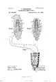
- Figure l is a perspective of my improved brake ratchet handle.l
- Fig. 2 is a sect-ion taken on the line w', or', of Fig. 1.
- Fig. 3 is a section taken on the line ,002002, ofFig. 2.
- Fig. et is a perspective of the ratchet with the handle socket removed.
- Fig. 5 is a perspective of the brake handle shown as removed.
- Fig. 6 is a view of the socket spring, and Fig. 7 of the pin by which the handle and socket parts are connected.
- the letter H designates the handle made with the socket S.
- the interior of this socket has two vertically placed angularsurfaces F', F, making an arc-form division of the socket interior and one of the rounded surfaces O between veach of the angular surfaces.
- the letter D designates the ratchet made with the head H2, and R designates the ratchet part formed on the bottom of the head adapted to engage with the ratchet part R2, formed on the ratchet-body B.
- the head of the ratchet is cutaway upon each side in arc-form lineation with the head to form the angular surfaces F2, F2, having the intermediately rounded surfaces O2.
- the letter S2 designates a stem that is upwardly projected from the head to receive a spiral spring D2, that encircles it between the top of the head and upper end of the socket.
- the letter P designates a pin adapted to be passed through the handle socket and key into an annular recess N, made in the spindle head as shown at ⁇ Fig. 2.
- the handle As thus made when the handle is turned in the direction of the interlocking socket parts, it rotates the brake rod R3, and when reversed it rises over and descends on the coincident bevels of the ratchet parts.
- the handle socket wears irregularly so as to become loose, and this difticultyl avoid by using only the two angular surfaces to engage with the head and leaving the rounded journaling surfaces between the angular surfaces of the head and socket intact.
- a ratchet brake handle the combination with the handle H, made with the socket S, having the two interior angular surfaces F, F', and intermediate rounded journaling surfaces O, O; ofthe ratchet D, made with the ratchet parts R', R2, connecting brake-rod R3,
- ratchet head made with the angular surfaces F2, F2, and intermediately arranged rounded journaling surfaces O2, O2, and having the stem S2; and the spiral spring D2, encircling said stem between the head and top of the socket interior, substantially in the manner as and for the purposes set forth.
Landscapes
- Engineering & Computer Science (AREA)
- General Engineering & Computer Science (AREA)
- Mechanical Engineering (AREA)
- Tires In General (AREA)
Description
(No Model.) 2 Sheets-Sheet' 1.
J. SEEBERGER.
GAR BRAKE RATGHET HANDLE. No. 528,492. Patented Oct. 30, v18941.
llllllllllllllll WNEZEuf-l lnk/ENTER' (No Model.)
` 2 Sheets-Sheet 2. J. SEEBERGER.
CAR BRAKE RATGHBT HANDLE.
No. 528,492. Patented oct. 30,1894.
ai-: .27- Q .a S :TIE
Tg1 O i I HI-ll NIH NVE wma-p# RHIN/IM@ N m,
@MZ/77m@ lrIo UNITED STATES PATENT OFFICE.
JOHN SEEBERGER, OF WEST TROY, NEW YORK.
CAR-BRAKE-RATCH ET HAN DLE.
SPECIFICATION forming part of Letters Patent No. 528,492, dated October 30, 1894. Application filed April 18.1894. Serial No. 507,973. (No model.)
To @ZZ whom t may concern:
Beit known that I, .TOEN SEEBEEGEE, of the village of West Troy, county of Albany, and State of New York, have invented new and useful Improvements 'in Oar-Brake- Ratchet Handles, of which the following is a specification.
My invention relates to improvements in car brake ratchet handles, and the object and purpose of my invention is to better adapt this class of devices to the uses for which they are designed. j
My improvement in the main relates to the man-ner of making the socket connection between the handle and the movable parts of the ratchet. As heretofore produced this connection has been made with a rectangular head formed on the ratchet part, and a recessed socket part made in thehandle corresponding on its inner faces to receive the rectangular surfaces of the ratchet head. Pins have also been used which projected downwardly from the handle socket to enter holes or grooves in the ratchet head, and vertical ribs have been cast on the ratchet head to enter vertical grooves made in the socket.
By my improvement I combine with two rectangular faces vertically arranged on the ratchet head, two rounded surfaces at each side of the head oppositely placed with one of the rounded journaling faces between each two of the rectangular faces, and then making the socket to receive the ratchet head with two vertically placed rectangular faces and a rounded journaling face between each of the latter.
This improvement increases the journaling surface of the ratchet handle when reversing and makes its operation more reliable.
Accompanying this specification to form a part of it there are two plates of drawings containing seven figures illustrating my invention, with the same designation of parts by letter reference used in all of them.
Of the illustrations Figure l is a perspective of my improved brake ratchet handle.l
Fig. 2 is a sect-ion taken on the line w', or', of Fig. 1. Fig. 3 is a section taken on the line ,002002, ofFig. 2. Fig. et is a perspective of the ratchet with the handle socket removed. Fig. 5 isa perspective of the brake handle shown as removed. Fig. 6 is a view of the socket spring, and Fig. 7 of the pin by which the handle and socket parts are connected.
The several parts thus illustrated are designated by letter reference and the function of the parts is described as follows:
The letter H designates the handle made with the socket S. The interior of this socket has two vertically placed angularsurfaces F', F, making an arc-form division of the socket interior and one of the rounded surfaces O between veach of the angular surfaces.
4 The letter D designates the ratchet made with the head H2, and R designates the ratchet part formed on the bottom of the head adapted to engage with the ratchet part R2, formed on the ratchet-body B. The head of the ratchet is cutaway upon each side in arc-form lineation with the head to form the angular surfaces F2, F2, having the intermediately rounded surfaces O2.
The letter S2 designates a stem that is upwardly projected from the head to receive a spiral spring D2, that encircles it between the top of the head and upper end of the socket.
The letter P .designates a pin adapted to be passed through the handle socket and key into an annular recess N, made in the spindle head as shown at` Fig. 2.
As thus made when the handle is turned in the direction of the interlocking socket parts, it rotates the brake rod R3, and when reversed it rises over and descends on the coincident bevels of the ratchet parts. When made with a short or limited journaling area, the handle socket wears irregularly so as to become loose, and this difticultyl avoid by using only the two angular surfaces to engage with the head and leaving the rounded journaling surfaces between the angular surfaces of the head and socket intact.
Having thus described my invention, what I claim, and desire to secure by Letters Patent, is-
In a ratchet brake handle the combination with the handle H, made with the socket S, having the two interior angular surfaces F, F', and intermediate rounded journaling surfaces O, O; ofthe ratchet D, made with the ratchet parts R', R2, connecting brake-rod R3,
IOO
and having the ratchet head made with the angular surfaces F2, F2, and intermediately arranged rounded journaling surfaces O2, O2, and having the stem S2; and the spiral spring D2, encircling said stem between the head and top of the socket interior, substantially in the manner as and for the purposes set forth.
Signed at Troy, New York, this 8th day of April, 1893, and in the presence of the two ro witnesses whose names are hereto written.
JOHN SEEBERGER.
Witnesses:
W. E. HAGAN, CHARLES S. BRINTNALL.
Publications (1)
| Publication Number | Publication Date |
|---|---|
| US528492A true US528492A (en) | 1894-10-30 |
Family
ID=2597280
Family Applications (1)
| Application Number | Title | Priority Date | Filing Date |
|---|---|---|---|
| US528492D Expired - Lifetime US528492A (en) | Car-brake-ratchet handle |
Country Status (1)
| Country | Link |
|---|---|
| US (1) | US528492A (en) |
-
0
- US US528492D patent/US528492A/en not_active Expired - Lifetime
Similar Documents
| Publication | Publication Date | Title |
|---|---|---|
| US528492A (en) | Car-brake-ratchet handle | |
| US1146933A (en) | Friction-spring. | |
| US698159A (en) | Universal joint. | |
| US1010108A (en) | Mooring-staple. | |
| US1161641A (en) | Air-hose coupling. | |
| US531662A (en) | Device for cutting boiler-tubes | |
| US1206320A (en) | Safety-cock for gas-ranges. | |
| US1118456A (en) | Clutch device. | |
| US252406A (en) | Saucer for mugs | |
| US470887A (en) | Chamber or commode pot | |
| US986772A (en) | Folding steel rule. | |
| US1308490A (en) | Stud-driver | |
| US1675063A (en) | Clutch construction | |
| US333199A (en) | Ratchet-wrench | |
| US744441A (en) | Spigot. | |
| US1169974A (en) | Transmission-lock. | |
| US712725A (en) | Knuckle-joint. | |
| US1127717A (en) | Ratchet-wrench. | |
| US1118657A (en) | Split link for chains. | |
| US869804A (en) | Dumping-car. | |
| US838118A (en) | Ratchet-drill. | |
| US1109218A (en) | Power-transmission mechanism. | |
| US1242205A (en) | Tool-driver. | |
| US634780A (en) | Railway-frog. | |
| US852140A (en) | Locking device for beer-coolers. |