US1127717A - Ratchet-wrench. - Google Patents
Ratchet-wrench. Download PDFInfo
- Publication number
- US1127717A US1127717A US77153913A US1913771539A US1127717A US 1127717 A US1127717 A US 1127717A US 77153913 A US77153913 A US 77153913A US 1913771539 A US1913771539 A US 1913771539A US 1127717 A US1127717 A US 1127717A
- Authority
- US
- United States
- Prior art keywords
- head
- wrench
- handle
- recess
- engaging member
- Prior art date
- Legal status (The legal status is an assumption and is not a legal conclusion. Google has not performed a legal analysis and makes no representation as to the accuracy of the status listed.)
- Expired - Lifetime
Links
Images
Classifications
-
- B—PERFORMING OPERATIONS; TRANSPORTING
- B25—HAND TOOLS; PORTABLE POWER-DRIVEN TOOLS; MANIPULATORS
- B25B—TOOLS OR BENCH DEVICES NOT OTHERWISE PROVIDED FOR, FOR FASTENING, CONNECTING, DISENGAGING OR HOLDING
- B25B13/00—Spanners; Wrenches
- B25B13/46—Spanners; Wrenches of the ratchet type, for providing a free return stroke of the handle
- B25B13/461—Spanners; Wrenches of the ratchet type, for providing a free return stroke of the handle with concentric driving and driven member
- B25B13/462—Spanners; Wrenches of the ratchet type, for providing a free return stroke of the handle with concentric driving and driven member the ratchet parts engaging in a direction radial to the tool operating axis
- B25B13/463—Spanners; Wrenches of the ratchet type, for providing a free return stroke of the handle with concentric driving and driven member the ratchet parts engaging in a direction radial to the tool operating axis a pawl engaging an externally toothed wheel
Definitions
- This invention relates to new and useful improvements in wrenches and has particular reference to ratchet wrenches which may be adjusted to cause right or left hand rotation. e
- the object of the invention resides in the provision of a wrench which may be so adjusted as to produce right or left hand rotation of the work receiving socket upon rotation of the handle and which may also be adjusted to lock the work receiving socket against movement with relation to the handle.
- a further object is to simplify the gen eral structure and to increase the efiiciency and ease of manipulation of devices of this character.
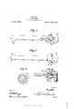
- Figure 1 is a top plan view of the im-' proved wrench
- Fig. 2 is a bottom plan view with the rotatable'fwork engaging member removed
- Fig. 3 is a plan view of the work engaging member
- ldig. d is a sectional view on the line 4-4 of Fig. 1.
- 5 designates the handle portion of the wrench which is provided at its forward end with an enlarged circular head 6 carrying the rotatable work engaging member 7 by means of a bolt 8 passed centrally through the member 7 and the head 6.
- the work engaging member is provided on its outer face with a suitable opening or recess 9 for receiving the work.
- the free end of the handle may be provided with a suitable wrench recess 11.
- Means are provided for rotating the work engaging member in a clockwise or a counterclockwise direction selectively upon rocking the handle 5.
- These means include a series of ratchet teeth 11 arranged on the inner face of the work engaging member 7 in a circle having at its center the pivotal connection of the member with the head 6.
- the head 6 is provided adjacent these teeth with a recess 12 on its inner face and has provided in its outer face a second recess 13 which extends inwardly of the recess 12 and has one of its ends overlapping the ends of the said recess.
- a passage 13 through the head connects the said ends.
- a pawl 14 is provided and comprising an intermediate portion 15 centrally pivoted in the passage 14 by a pin passed through the portion 15 and through the head.
- the lower end of the portion is provided with a lateral tooth engaging extension 16 at its lower end extending adjacent the recess 12 and normally forced into engagement with the ratchet teeth 11 by a spring 17 positioned in the recess.
- the upper of ratchet teeth 19 are provided arranged in a circle concentric with and inwardly of the circle of ratchet teeth 11.
- a pawl 20 isiprovided which is similar to the pawl 14 and. which is similarly pivotally mounted'so that the specific description of the pawl 14: and the mounting thereof will suffice for the pawl 20.
- a leaf spring 21 has one end secured as at 22 to the inner end of the handle and extends on to the head 6 so as to engage either of thereare ward extensions 18 of the pawls and force them into the recess 18 and thus force the extensions 16 into the recess 12 against the action of the spring 17 to hold the respective pawl in inoperative position.
- the spring 21 is allowed to rest on the head 6 and not engage either of the pawls, allowing both to be in operative position'to thus lock the head.
- a wrench comprising a handle having a head, a Work holding member rotatably connected with the head and having ratchet teeth formed thereon confronting the head, a pair of pawls passed through the head and adapted to normally engage at one end with corresponding ratchet teeth, and means shiftable from one to the other of the pawls at their opposite ends, for holding either pawl at times from engagement with the corresponding ratchet teeth.
- a ratchet wrench comprising a handle, a head thereon, a work engaging member pivoted on said head and provided upon its head engaging surface with two concentric series of oppositely disposed ratchet teeth, said head being provided with recesses, a pair of pawls pivoted within said recesses and having their inner ends normally spring pressed into engagement with said series of ratchet teeth, and a spring pivoted upon said handle and engageable with the outer end of either of said pawls whereby the pawl may be released from engagement with the respective series of ratchet teeth, the disengagement of said releasing spring from both of said pawls causing said pawls to lock said work engaging member upon said head.
Description
H. L. ASH.
RATOHET WRENCH.
APPLICATION FILED JUNE 3. 1913.
1,127,717. I Patented Feb. 9, 1915.
wi/fmeooeo THE NORRIS PETERS Cov PHO'ro'LlTHo. wAsHlNcroN. D
in en HARRY I. ASH, OF SOMERSET, PENNSYLVANIA.
IRATCHETJVRENCH.
Application filed June 3, 1913.
To all whom it may concern:
Be it known that I, HARRY L. Ass :1. citizen of the United States, residing at Somerset, in the county of Somerset, State of Pennsylvania, have invented certain new and useful Improvements in Ratchet- /Vrenches; and I do hereby declare the following to be a full, clear, and exact description of the invention, such as will enable others skilled in the art to which it appertains to make and use the same.
This invention relates to new and useful improvements in wrenches and has particular reference to ratchet wrenches which may be adjusted to cause right or left hand rotation. e
The object of the invention resides in the provision of a wrench which may be so adjusted as to produce right or left hand rotation of the work receiving socket upon rotation of the handle and which may also be adjusted to lock the work receiving socket against movement with relation to the handle.
A further object is to simplify the gen eral structure and to increase the efiiciency and ease of manipulation of devices of this character.
With these and other objects in view, the invention resides in the novel combination, formation and arrangement of parts to be more fully hereinafter described and illustrated in the accompanying drawings and particularly pointed out in the claims hereto appended.
Reference is had to the accompanying drawings wherein similar characters of reference designate corresponding parts throughout the several views, and in which:
Figure 1 is a top plan view of the im-' proved wrench, Fig. 2 is a bottom plan view with the rotatable'fwork engaging member removed, Fig. 3 is a plan view of the work engaging member, and ldig. d is a sectional view on the line 4-4 of Fig. 1.
Referring now more particularly to the drawings, wherein is shown the preferred form of the invention, 5 designates the handle portion of the wrench which is provided at its forward end with an enlarged circular head 6 carrying the rotatable work engaging member 7 by means of a bolt 8 passed centrally through the member 7 and the head 6. The work engaging member is provided on its outer face with a suitable opening or recess 9 for receiving the work.
Specification of Letters Eatent.
Patented Feb. 9, 1915.
Serial No. 771,539.
The free end of the handle may be provided with a suitable wrench recess 11.
Means are provided for rotating the work engaging member in a clockwise or a counterclockwise direction selectively upon rocking the handle 5. These means include a series of ratchet teeth 11 arranged on the inner face of the work engaging member 7 in a circle having at its center the pivotal connection of the member with the head 6. The head 6 is provided adjacent these teeth with a recess 12 on its inner face and has provided in its outer face a second recess 13 which extends inwardly of the recess 12 and has one of its ends overlapping the ends of the said recess. A passage 13 through the head connects the said ends. For causing clockwise motion of the work engaging member a pawl 14: is provided and comprising an intermediate portion 15 centrally pivoted in the passage 14 by a pin passed through the portion 15 and through the head. The lower end of the portion is provided with a lateral tooth engaging extension 16 at its lower end extending adjacent the recess 12 and normally forced into engagement with the ratchet teeth 11 by a spring 17 positioned in the recess. To provide means whereby the pawl may be rocked so that its extension 16 is seated in the recess 12 and thus held in operative position the upper of ratchet teeth 19 are provided arranged in a circle concentric with and inwardly of the circle of ratchet teeth 11. A pawl 20 isiprovided which is similar to the pawl 14 and. which is similarly pivotally mounted'so that the specific description of the pawl 14: and the mounting thereof will suffice for the pawl 20. In order that either of the pawls may be locked in inoperative position so as to permit rotation of the handle with relation to the work engaging member 7, a leaf spring 21 has one end secured as at 22 to the inner end of the handle and extends on to the head 6 so as to engage either of thereare ward extensions 18 of the pawls and force them into the recess 18 and thus force the extensions 16 into the recess 12 against the action of the spring 17 to hold the respective pawl in inoperative position. If it'is desired to lock the handle portion with rela tion to the work engaging member so that the work engaging member will always rotate with the handle member, the spring 21 is allowed to rest on the head 6 and not engage either of the pawls, allowing both to be in operative position'to thus lock the head.
From the foregoing it will be observed that a very simple structure has been provided which will eiiiciently perform all of the functions set forth.
What is claimed is:
1. A wrench comprising a handle having a head, a Work holding member rotatably connected with the head and having ratchet teeth formed thereon confronting the head, a pair of pawls passed through the head and adapted to normally engage at one end with corresponding ratchet teeth, and means shiftable from one to the other of the pawls at their opposite ends, for holding either pawl at times from engagement with the corresponding ratchet teeth.
2. A ratchet wrench comprising a handle, a head thereon, a work engaging member pivoted on said head and provided upon its head engaging surface with two concentric series of oppositely disposed ratchet teeth, said head being provided with recesses, a pair of pawls pivoted within said recesses and having their inner ends normally spring pressed into engagement with said series of ratchet teeth, and a spring pivoted upon said handle and engageable with the outer end of either of said pawls whereby the pawl may be released from engagement with the respective series of ratchet teeth, the disengagement of said releasing spring from both of said pawls causing said pawls to lock said work engaging member upon said head.
In testimony whereof, I affix my signature, in the presence of two witnesses,
HARRY L. ASH. Witnesses:
W. IRA BAKER, E. J. BAKER.
Copies of this patent may be obtained for five cents each, by addressing the Commissioner of Patents,
Washington, D. G.
Priority Applications (1)
| Application Number | Priority Date | Filing Date | Title |
|---|---|---|---|
| US77153913A US1127717A (en) | 1913-06-03 | 1913-06-03 | Ratchet-wrench. |
Applications Claiming Priority (1)
| Application Number | Priority Date | Filing Date | Title |
|---|---|---|---|
| US77153913A US1127717A (en) | 1913-06-03 | 1913-06-03 | Ratchet-wrench. |
Publications (1)
| Publication Number | Publication Date |
|---|---|
| US1127717A true US1127717A (en) | 1915-02-09 |
Family
ID=3195863
Family Applications (1)
| Application Number | Title | Priority Date | Filing Date |
|---|---|---|---|
| US77153913A Expired - Lifetime US1127717A (en) | 1913-06-03 | 1913-06-03 | Ratchet-wrench. |
Country Status (1)
| Country | Link |
|---|---|
| US (1) | US1127717A (en) |
Cited By (1)
| Publication number | Priority date | Publication date | Assignee | Title |
|---|---|---|---|---|
| US5603247A (en) * | 1995-10-06 | 1997-02-18 | Wei; Hung-Yin | Ratchet wrench |
-
1913
- 1913-06-03 US US77153913A patent/US1127717A/en not_active Expired - Lifetime
Cited By (1)
| Publication number | Priority date | Publication date | Assignee | Title |
|---|---|---|---|---|
| US5603247A (en) * | 1995-10-06 | 1997-02-18 | Wei; Hung-Yin | Ratchet wrench |
Similar Documents
| Publication | Publication Date | Title |
|---|---|---|
| US893097A (en) | Reversible ratchet-wrench. | |
| US915446A (en) | Wrench. | |
| US726012A (en) | Nut-wrench. | |
| US951056A (en) | Wrench. | |
| US685698A (en) | Wrench. | |
| US1127717A (en) | Ratchet-wrench. | |
| US455133A (en) | Fredrick samuel turing | |
| US1169007A (en) | Wrench. | |
| US1198822A (en) | Spanner. | |
| US891615A (en) | Wrench. | |
| US754012A (en) | Wrench. | |
| US478680A (en) | Ratchet-wrench | |
| US1099572A (en) | Ratchet-wrench. | |
| US861524A (en) | Wrench. | |
| US594023A (en) | Wrench | |
| US509810A (en) | Ratchet-wrench | |
| US119317A (en) | Thomas a | |
| US770699A (en) | Wrench | |
| US1071687A (en) | Pipe-wrench. | |
| US838099A (en) | Wrench. | |
| US561823A (en) | Wrench | |
| US683167A (en) | Reversible ratchet. | |
| US883309A (en) | Ratchet-wrench. | |
| US228827A (en) | peters | |
| US1173200A (en) | Wrench of the alligator type. |