US5284419A - Propeller with blades which can be twisted - Google Patents
Propeller with blades which can be twisted Download PDFInfo
- Publication number
- US5284419A US5284419A US07/927,388 US92738892A US5284419A US 5284419 A US5284419 A US 5284419A US 92738892 A US92738892 A US 92738892A US 5284419 A US5284419 A US 5284419A
- Authority
- US
- United States
- Prior art keywords
- rib
- ribs
- spar
- propeller according
- rod element
- Prior art date
- Legal status (The legal status is an assumption and is not a legal conclusion. Google has not performed a legal analysis and makes no representation as to the accuracy of the status listed.)
- Expired - Lifetime
Links
- 238000005452 bending Methods 0.000 claims abstract description 14
- 230000008878 coupling Effects 0.000 claims abstract description 7
- 238000010168 coupling process Methods 0.000 claims abstract description 7
- 238000005859 coupling reaction Methods 0.000 claims abstract description 7
- 238000010276 construction Methods 0.000 claims description 10
- 239000013013 elastic material Substances 0.000 claims description 8
- 230000008859 change Effects 0.000 claims description 6
- 239000006260 foam Substances 0.000 claims 1
- 239000002984 plastic foam Substances 0.000 claims 1
- 230000008901 benefit Effects 0.000 description 4
- 230000010355 oscillation Effects 0.000 description 3
- 230000000284 resting effect Effects 0.000 description 3
- 238000006073 displacement reaction Methods 0.000 description 2
- 230000002349 favourable effect Effects 0.000 description 2
- 239000012530 fluid Substances 0.000 description 2
- 238000000034 method Methods 0.000 description 2
- 230000008569 process Effects 0.000 description 2
- 230000003014 reinforcing effect Effects 0.000 description 2
- 230000009194 climbing Effects 0.000 description 1
- 230000006835 compression Effects 0.000 description 1
- 238000007906 compression Methods 0.000 description 1
- 230000000694 effects Effects 0.000 description 1
- 239000000463 material Substances 0.000 description 1
Images


Classifications
-
- B—PERFORMING OPERATIONS; TRANSPORTING
- B64—AIRCRAFT; AVIATION; COSMONAUTICS
- B64C—AEROPLANES; HELICOPTERS
- B64C27/00—Rotorcraft; Rotors peculiar thereto
- B64C27/32—Rotors
- B64C27/46—Blades
-
- B—PERFORMING OPERATIONS; TRANSPORTING
- B64—AIRCRAFT; AVIATION; COSMONAUTICS
- B64C—AEROPLANES; HELICOPTERS
- B64C11/00—Propellers, e.g. of ducted type; Features common to propellers and rotors for rotorcraft
- B64C11/30—Blade pitch-changing mechanisms
Definitions
- the invention relates to a propeller with blades which can be twisted.
- a propeller is operated for producing the forward-drive force of an aircraft, optimum blade pitch angles can be maintained over the entire blade length in different flight situations (takeoff, climbing flight, cruise flight) in the case of a propeller with blades which can be twisted, with the advantage of a thrust and efficiency which are favourable in each case for these different flight situations, and as little noise generation as possible.
- the propeller is used as a rotor in hovering flight, in a position pivoted through 90 angular degrees with respect to that in cruise flight.
- a variable blade twist makes possible an optimum blade pitch angle over the entire blade length in such a case as well, both in the different phases of forward flight and in the hovering flight phase, in contrast to a propeller with a rigid blade twist which has an optimum setting with the most favourable thrust and efficiency and as little noise generation as possible only in a single operating situation which is predetermined by the design point.
- DE-OS 2,164,648 discloses the facilitating of a variable twist of the blade via a strip system within the propeller blade in conjunction with a rigid main spar and conical adjusting tubes resting thereon.
- DE-OS 1,531,475 and DE-AS 1,531,476 describe a propeller having a variable blade twist, in which the twist is achieved by means of ribs which are guided on a spar in helical grooves and can be displaced axially on the spar.
- blade cavities can be rotated around the blade axis by means of a different fluid filling, as a result of which it is intended to facilitate a variable blade twist.
- a propeller of the type mentioned initially has been disclosed in U.S. Pat. No. 2,627,928.
- the individual ribs which are arranged on the blade spar such that they can rotate are connected at the leading edge of the blade to in each case one reinforcing element and at the trailing edge to in each case one leaf spring element.
- the intermediate ribs are also moved by the elastic outer skin enclosing the blade. Since, in particular, the leaf spring elements form a type of chain which deforms in an unpredictable manner under the influence of the centrifugal force, bending and torsion oscillations occur in operation which negate the advantages of the adjustment capability again.
- the object of the invention is to create a propeller of the type mentioned initially in which, on the one hand, the high centrifugal-force stresses of the blade are adequately absorbed despite the elastic regions which are required for variability of the twist, and in which, in particular, the coupling between adjacent ribs takes place such that an undesired adjustment of the elastic regions under the influence of the centrifugal force and an undesired adjustment of the blade geometry resulting from this are prevented, with a simple blade construction.
- DE-OS 2,164,648 discloses the facilitating of a variable twist of the blade via a strip system within the propeller blade in conjunction with a rigid main spar and conical adjusting tubes resting thereon.
- DE-OS 1,531,475 and DE-AS 1,531,476 describe a propeller having a variable blade twist, in which the twist is achieved by means of ribs which are guided on a spar in helical grooves and can be displaced axially on the spar.
- blade cavities can be rotated around the blade axis by means of a different fluid filling, as a result of which it is intended to facilitate a variable blade twist.
- a propeller of the type mentioned initially has been disclosed in U.S. Pat. No. 2,627,928.
- the individual ribs which are arranged on the blade spar such that they can rotate are connected at the leading edge of the blade to in each case one reinforcing element and at the trailing edge to in each case one leaf spring element.
- the intermediate ribs are also moved by the elastic outer skin enclosing the blade. Since, in particular, the leaf spring elements form a type of chain which deforms in an unpredictable manner under the influence of the centrifugal force, bending and torsion oscillations occur in operation which negate the advantages of the adjustment capability again.
- a further example for a propeller of the type mentioned initially is specified in U.S. Pat. No. 2,584,663.
- the object of the invention is to create a propeller of the type mentioned initially in which, on the one hand, the high centrifugal-force stresses of the blade are adequately absorbed despite the elastic regions which are required for variability of the twist, and in which, in particular, the coupling between adjacent ribs takes place such that an undesired adjustment of the elastic regions under the influence of the centrifugal force and an undesired adjustment of the blade geometry resulting from this are prevented, with a simple blade construction.
- the rod element designed and constructed according to the invention is deformed along a helical line when two ribs are rotated relative to one another by the application of external force, all the ribs being rotated on the spar by the rod element or rod elements such that a continuous twisting of the basic blade structure given by the ribs takes place.
- the ribs may be adjusted.
- the essential feature is that two ribs which are covered by one rod element are adjusted with respect to one another.
- a further feature of the invention relates to the connecting points of the ribs to a rod element.
- One preferred configuration of the invention may consist in that the ribs are split into rib segments which can be rotated with respect to one another around the longitudinal axis of the ribs running at right angles to the spar.
- the ribs can match themselves better to the twist so that the height jumps which have been referred to between the ribs during blade twisting advantageously become negligibly small.
- This matching of the individual rib segments to the blade twist can take place by a non-rotatable mechanical connection of rib sections to a rod element allocated to them or, as well, by the force effect of an elastic layer enveloping the propeller blade or, by filling the intermediate spaces between the ribs with a viscous-elastic material.
- elements which are suitably matched to the profile contour are formed flat and consist of a non-elastic material can be used as the basic structure of the ribs, as a result of which, on the one hand, the high centrifugal forces of a rotating propeller blade can be coped with advantageously and, on the other hand, the required twisting capability in a small circumference is given.
- slots can be incorporated into the elements. If necessary, these elements can be supported at one or more points against deforming forces and forces which change the profile contour.
- rib rods per rib which can rotate on the spar, and run in the rib longitudinal axis, that is to say at right angles to the spar, support the elements following the profile contour on one side
- the adjusting device that is to say the rod elements, engaging on the other side, the rotation introduced in two adjacent rib rods of one rib differing slightly so that, in consequence, torsioning of the ribs takes place at the same time.
- Two rod elements expediently run parallel to the spar, to be precise on the blade leading edge side and the blade trailing side, so that the engagement points are arranged on both sides of the spar.
- the rib rods are supported on the spar by means of bearing rings such that they can rotate, these bearing rings can then be constructed such that they are used for supporting the elements against the deforming forces and forces which change the profile contour.
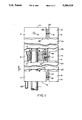
- FIG. 1 shows a partially cut-away view of a first configuration of a propeller according to the invention
- FIG. 2 shows a perspective partial view of a second configuration of a propeller
- FIG. 3 shows a section view along the section line III--III in FIG. 2.
- FIG. 1 shows a part of a propeller according to the invention. It has a spar 1, which is stiff in torsion and bending, is resistant to tension and is of cylindrical construction, on which ribs 4, 5 and 6 are arranged, from the blade root 2 to the blade tip 3, such that they can rotate around the spar.
- Each of these ribs is constructed from rib segments 7, 8; 9, 10; 11, 12, the first rib segment 7, 9, 11 of each rib being supported in a sleeve 13 (see rib segment 9) on the spar 1 such that it can rotate around its axis.
- the first rib segment is secured against lateral displacement on the spar 1 as a consequence of the centrifugal force occurring in operation, which acts in the direction of the arrow F.
- the second rib segment 8, 10, 12 of each rib is connected to the first rib segment 7, 9, 11 in each case by means of a cylindrical bolt 16, 17, 18.
- each rib segment 7, 9, 11 has a depression, of which only the depression 9a of the rib segment 9 can be seen.
- Sleeves 19, in which the bolts 16, 17 and 18 are supported such that they can rotate, are inserted into these depressions 9a. Since the second rib segments 8, 10, 12 are firmly connected to the bolts 16, 17, 18, the second rib segments 8, 10, 12 are connected to the front rib sections 7, 9, 11 by the bolts 16 to 18, such that they can rotate.
- the three ribs 4, 5 and 6 are covered by a rod element 20 which runs parallel to the spar 1 on its side facing the blade trailing edge.
- the rod element 20 is connected to the ribs 4, 5 and 6 in each case in the region of the bolts 16 to 18, the bolts 16, 17, 18 in each case passing through elongated holes in the rod element 20, which cannot be seen in FIG. 1.
- the rod element 20 is designed as a flat strip with an elongated rectangular cross-section, such as the corresponding rod element of the configuration according to FIGS. 2 and 3, and can be seen only with its narrow side in FIG. 1.
- the bolts 16, 17 and 18 are expediently constructed to be rectangular in cross-section, to be precise in the region in which they are guided through the elongated hole in the rod element 20. In consequence, a rotation-free mechanical connection is achieved between the rod element 20 and the second rib segments 8, 10 and 12.
- the outer rib 6, arranged at the blade tip 3, is fixed on the spar 1, such that it cannot rotate, by means of a pin 21 which passes through the rib segment 11 and the spar 1 at right angles.
- the inner rib 4, arranged at the blade root 2, can rotate with respect to the spar 1 via an adjusting device of which FIG. 1 shows only a peg 22 which transmits the adjusting force and is firmly connected to the first rib segment 7 of the rib 4.
- the intermediate spaces 23, 24, 25 and 26 located between the ribs 4 and 6, as well as the intermediate spaces 27 to 29 between the first and the second rib segments are advantageously filled with elastic material while, on the other hand, the rib segments themselves consist of hard material which does not deform elastically, or deforms only slightly, even under the influence of high centrifugal forces.
- the propeller blade is surrounded by an elastic, thin layer 30 which rests on the ribs 4 to 6 and the rib segments 7 to 12.
- FIG. 2 and 3 A further configuration of the invention can be found in FIG. 2 and 3.
- a propeller blade according to FIG. 2 has a spar 40, which is stiff in torsion and bending, on which the ribs 41, 42 are supported such that they can rotate.
- Each of these ribs has flat elements 43, 44, 45, which are formed corresponding to the profile contour and of which the element 43 forms the blade nose and the element 45 the blade trailing edge of the propeller blade.
- the elements 43 and 45 are accordingly formed like a box in a virtually closed manner, their inner walls facing the spar being formed by overlapping the ends 46, 47 and 52, 53 respectively of the flat elements 43, 45.
- the central element 44 is assembled from two U-shaped subelements 54 and 55, whose limbs 48, 49 and 50, 51 respectively likewise overlap and in consequence the two elements 54 and 55 form a closed box.
- Two rod elements 56 and 57 according to the invention and running parallel to the spar 40 are used as the adjusting device for rotating the ribs 41, 42 on the spar 40.
- Each rib 41, 42 has two rib rods 60, 61 which are arranged side-by-side, run in the rib longitudinal axis and at right angles to the spar 40 and are in each case connected firmly to a bearing ring 58, 59, by means of which they are supported on the spar 40 such that they can rotate.
- the bearing rings 58 and 59 surround the spar 40.
- the rod elements 56 and 57 which run on both sides of the spar and parallel thereto, and are constructed and arranged in a similar manner as the rod element 20 in FIG.
- the rod elements 56 and 57 having elongated holes 62, 63 and 64 and 65 respectively which permit a certain movement of the rod elements 56 and 57 with respect to the rib rods 60 and 61 when the blade twist is being changed.
- the individual ribs 41, 42 are twisted around their rib longitudinal axis via the two rib rods 60 and 61.
- the rod elements 56, 57 are connected to the rib rods 60, 61 via the elongated holes 62, 63; 64, 65 and introduce the adjusting forces to the rib rods and hence to the ribs.
- the rib rods 60, 61 run through the mutually overlapping ends of the elements 43, 44, 45 so that the elements 43 to 45 are also connected to the rib rods 60, 61.
- the elements 43 to 45 which are used as rib segments, rotate with respect to one another and intrinsically so that a smooth overall surface is formed.
- the subelements 54 and 55 are supported at two points 66, 67 on the bearing rings 59, 58 against externally acting forces which change the profile contour.
- the propeller blade is surrounded by a thin elastic layer 68 resting on the elements 43 to 45 (see FIG. 2).
Landscapes
- Engineering & Computer Science (AREA)
- Aviation & Aerospace Engineering (AREA)
- Mechanical Engineering (AREA)
- Toys (AREA)
- Wind Motors (AREA)
- Vibration Dampers (AREA)
Applications Claiming Priority (2)
| Application Number | Priority Date | Filing Date | Title |
|---|---|---|---|
| DE4010211A DE4010211A1 (de) | 1989-12-27 | 1990-03-30 | Propeller mit verwindbaren blaettern |
| DE4010211 | 1990-03-30 |
Publications (1)
| Publication Number | Publication Date |
|---|---|
| US5284419A true US5284419A (en) | 1994-02-08 |
Family
ID=6403389
Family Applications (1)
| Application Number | Title | Priority Date | Filing Date |
|---|---|---|---|
| US07/927,388 Expired - Lifetime US5284419A (en) | 1990-03-30 | 1991-04-01 | Propeller with blades which can be twisted |
Country Status (7)
| Country | Link |
|---|---|
| US (1) | US5284419A (de) |
| EP (1) | EP0522035B1 (de) |
| JP (1) | JP3150693B2 (de) |
| BR (1) | BR9106298A (de) |
| DE (1) | DE59103180D1 (de) |
| DK (1) | DK0522035T3 (de) |
| WO (1) | WO1991015399A1 (de) |
Cited By (9)
| Publication number | Priority date | Publication date | Assignee | Title |
|---|---|---|---|---|
| WO2003006825A1 (en) * | 2001-07-11 | 2003-01-23 | Hydra Tidal Energy Technology As | Plant, generator and propeller element for generating energy from watercurrents |
| US20070217918A1 (en) * | 2006-03-20 | 2007-09-20 | Baker Myles L | Lightweight composite truss wind turbine blade |
| US20090321558A1 (en) * | 2008-04-22 | 2009-12-31 | Pitt Dale M | Active twisting of an aircraft lifting surface via modulated clamping of substructure |
| GB2464678A (en) * | 2008-10-21 | 2010-04-28 | David Hostettler Wain | Twistable aircraft rotor blades |
| EP2716907A1 (de) * | 2012-10-05 | 2014-04-09 | Alstom Wind, S.L.U. | Rotorblatt und Verfahren zum Betrieb eines Rotorblatts |
| US20140154074A1 (en) * | 2012-12-05 | 2014-06-05 | The Boeing Company | Apparatus, System, and Method for Pitching and Twisting a Blade of a Rotorcraft |
| US9446843B2 (en) | 2012-03-27 | 2016-09-20 | The Boeing Company | Enhanced performance rotorcraft rotor blade |
| US9533754B2 (en) | 2014-04-19 | 2017-01-03 | The Boeing Company | Wing aerial refueling system |
| WO2021140368A1 (en) | 2020-01-10 | 2021-07-15 | Kruppa Laszlo | Improved efficiency propeller for aircraft |
Families Citing this family (1)
| Publication number | Priority date | Publication date | Assignee | Title |
|---|---|---|---|---|
| GB9701793D0 (en) * | 1997-01-29 | 1997-03-19 | Gay Geoffrey N W | Means for inputting characters or commands into a computer |
Citations (16)
| Publication number | Priority date | Publication date | Assignee | Title |
|---|---|---|---|---|
| FR752142A (fr) * | 1933-03-08 | 1933-09-16 | Hélice à pas variable et constant | |
| US2055928A (en) * | 1934-10-08 | 1936-09-29 | Russell R Hays | Rotating blade means for aircraft |
| US2244139A (en) * | 1937-01-21 | 1941-06-03 | Buckingham George Frederick | Propeller |
| US2369049A (en) * | 1943-09-28 | 1945-02-06 | Russell R Hays | Rotary wing aircraft |
| GB606784A (en) * | 1946-01-18 | 1948-08-19 | Fairey Aviat Co Ltd | Improvements in or relating to rotary wings for aircraft |
| US2584663A (en) * | 1946-06-27 | 1952-02-05 | Gen Electric | Variable warp airfoil |
| US2627928A (en) * | 1945-04-30 | 1953-02-10 | Alexander S Mullgardt | Propeller |
| US2978039A (en) * | 1958-05-01 | 1961-04-04 | Focke Henrich Carl Johann | Aircraft propellers for combined airplane-helicopter flying machines |
| US3096826A (en) * | 1961-08-07 | 1963-07-09 | Hughes Tool Co | Rotor blade for rotary-winged aircraft |
| US3227221A (en) * | 1963-11-29 | 1966-01-04 | You Pierre | Blade construction for helicopter |
| DE1281271B (de) * | 1964-11-23 | 1968-10-24 | Hugo T Grut | Luftschraube mit verstellbarer Blattverwindung |
| US3637168A (en) * | 1970-02-11 | 1972-01-25 | Ryan Aeronautical Co | Flexible blade retractable rotor aircraft |
| DE2164648A1 (de) * | 1971-12-24 | 1973-06-28 | Ver Flugtechnische Werke | Blattfluegel mit variabler verwindung fuer rotor- und luftschraubenblaetter |
| SU557300A1 (ru) * | 1974-07-05 | 1977-05-05 | Шосткинский Филиал Казанского Научно-Исследовательского Института Химических Продуктов | Способ измерени влажности волокнистых материалов |
| US4137010A (en) * | 1977-07-25 | 1979-01-30 | The United States Of America As Represented By The Administrator Of The National Aeronautics And Space Administration | Constant lift rotor for a heavier than air craft |
| US4619585A (en) * | 1983-07-28 | 1986-10-28 | Joe Storm | Wind turbine apparatus |
-
1991
- 1991-04-01 BR BR919106298A patent/BR9106298A/pt not_active IP Right Cessation
- 1991-04-01 US US07/927,388 patent/US5284419A/en not_active Expired - Lifetime
- 1991-04-01 JP JP50645691A patent/JP3150693B2/ja not_active Expired - Fee Related
- 1991-04-01 DK DK91907278.5T patent/DK0522035T3/da active
- 1991-04-01 WO PCT/EP1991/000612 patent/WO1991015399A1/de not_active Ceased
- 1991-04-01 EP EP91907278A patent/EP0522035B1/de not_active Expired - Lifetime
- 1991-04-01 DE DE59103180T patent/DE59103180D1/de not_active Expired - Fee Related
Patent Citations (16)
| Publication number | Priority date | Publication date | Assignee | Title |
|---|---|---|---|---|
| FR752142A (fr) * | 1933-03-08 | 1933-09-16 | Hélice à pas variable et constant | |
| US2055928A (en) * | 1934-10-08 | 1936-09-29 | Russell R Hays | Rotating blade means for aircraft |
| US2244139A (en) * | 1937-01-21 | 1941-06-03 | Buckingham George Frederick | Propeller |
| US2369049A (en) * | 1943-09-28 | 1945-02-06 | Russell R Hays | Rotary wing aircraft |
| US2627928A (en) * | 1945-04-30 | 1953-02-10 | Alexander S Mullgardt | Propeller |
| GB606784A (en) * | 1946-01-18 | 1948-08-19 | Fairey Aviat Co Ltd | Improvements in or relating to rotary wings for aircraft |
| US2584663A (en) * | 1946-06-27 | 1952-02-05 | Gen Electric | Variable warp airfoil |
| US2978039A (en) * | 1958-05-01 | 1961-04-04 | Focke Henrich Carl Johann | Aircraft propellers for combined airplane-helicopter flying machines |
| US3096826A (en) * | 1961-08-07 | 1963-07-09 | Hughes Tool Co | Rotor blade for rotary-winged aircraft |
| US3227221A (en) * | 1963-11-29 | 1966-01-04 | You Pierre | Blade construction for helicopter |
| DE1281271B (de) * | 1964-11-23 | 1968-10-24 | Hugo T Grut | Luftschraube mit verstellbarer Blattverwindung |
| US3637168A (en) * | 1970-02-11 | 1972-01-25 | Ryan Aeronautical Co | Flexible blade retractable rotor aircraft |
| DE2164648A1 (de) * | 1971-12-24 | 1973-06-28 | Ver Flugtechnische Werke | Blattfluegel mit variabler verwindung fuer rotor- und luftschraubenblaetter |
| SU557300A1 (ru) * | 1974-07-05 | 1977-05-05 | Шосткинский Филиал Казанского Научно-Исследовательского Института Химических Продуктов | Способ измерени влажности волокнистых материалов |
| US4137010A (en) * | 1977-07-25 | 1979-01-30 | The United States Of America As Represented By The Administrator Of The National Aeronautics And Space Administration | Constant lift rotor for a heavier than air craft |
| US4619585A (en) * | 1983-07-28 | 1986-10-28 | Joe Storm | Wind turbine apparatus |
Cited By (22)
| Publication number | Priority date | Publication date | Assignee | Title |
|---|---|---|---|---|
| WO2003006825A1 (en) * | 2001-07-11 | 2003-01-23 | Hydra Tidal Energy Technology As | Plant, generator and propeller element for generating energy from watercurrents |
| US7891950B2 (en) | 2006-03-20 | 2011-02-22 | Modular Wind Energy, Inc. | Lightweight composite truss wind turbine blade |
| US7517198B2 (en) | 2006-03-20 | 2009-04-14 | Modular Wind Energy, Inc. | Lightweight composite truss wind turbine blade |
| US20090191063A1 (en) * | 2006-03-20 | 2009-07-30 | Baker Myles L | Lightweight composite truss wind turbine blade |
| US20090196758A1 (en) * | 2006-03-20 | 2009-08-06 | Baker Myles L | Lightweight composite truss wind turbine blade |
| US7891949B2 (en) | 2006-03-20 | 2011-02-22 | Modular Wind Energy, Inc. | Lightweight composite truss wind turbine blade |
| US7891948B2 (en) | 2006-03-20 | 2011-02-22 | Modular Wind Energy, Inc. | Lightweight composite truss wind turbine blade |
| US20070217918A1 (en) * | 2006-03-20 | 2007-09-20 | Baker Myles L | Lightweight composite truss wind turbine blade |
| WO2008115265A1 (en) | 2007-03-20 | 2008-09-25 | Modular Wind Energy, Inc. | Lightweight composite truss wind turbine blade |
| US20090321558A1 (en) * | 2008-04-22 | 2009-12-31 | Pitt Dale M | Active twisting of an aircraft lifting surface via modulated clamping of substructure |
| US8128020B2 (en) * | 2008-04-22 | 2012-03-06 | The Boeing Company | Active twisting of an aircraft lifting surface via modulated clamping of substructure |
| GB2464678B (en) * | 2008-10-21 | 2013-04-10 | David Hostettler Wain | Dual swash plates |
| GB2464678A (en) * | 2008-10-21 | 2010-04-28 | David Hostettler Wain | Twistable aircraft rotor blades |
| US9446843B2 (en) | 2012-03-27 | 2016-09-20 | The Boeing Company | Enhanced performance rotorcraft rotor blade |
| EP2716907A1 (de) * | 2012-10-05 | 2014-04-09 | Alstom Wind, S.L.U. | Rotorblatt und Verfahren zum Betrieb eines Rotorblatts |
| WO2014053611A1 (en) * | 2012-10-05 | 2014-04-10 | Alstom Renovables España, S.L. | Wind turbine blade and methods of operating it |
| US9790917B2 (en) | 2012-10-05 | 2017-10-17 | Alstom Renewable Technologies | Wind turbine blade and methods of operating it |
| US20140154074A1 (en) * | 2012-12-05 | 2014-06-05 | The Boeing Company | Apparatus, System, and Method for Pitching and Twisting a Blade of a Rotorcraft |
| US9487291B2 (en) * | 2012-12-05 | 2016-11-08 | The Boeing Company | Apparatus, system, and method for pitching and twisting a blade of a rotorcraft |
| US9533754B2 (en) | 2014-04-19 | 2017-01-03 | The Boeing Company | Wing aerial refueling system |
| WO2021140368A1 (en) | 2020-01-10 | 2021-07-15 | Kruppa Laszlo | Improved efficiency propeller for aircraft |
| US11975816B2 (en) | 2020-01-10 | 2024-05-07 | László KRUPPA | High-efficiency propeller for aircraft |
Also Published As
| Publication number | Publication date |
|---|---|
| DE59103180D1 (de) | 1994-11-10 |
| DK0522035T3 (da) | 1994-11-07 |
| EP0522035B1 (de) | 1994-10-05 |
| JP3150693B2 (ja) | 2001-03-26 |
| BR9106298A (pt) | 1993-04-13 |
| JPH05505578A (ja) | 1993-08-19 |
| WO1991015399A1 (de) | 1991-10-17 |
| EP0522035A1 (de) | 1993-01-13 |
Similar Documents
| Publication | Publication Date | Title |
|---|---|---|
| DE2451860C3 (de) | Rotorblatt für Drehflügelflugzeuge | |
| US4281966A (en) | Multi-blade propellers | |
| US3669566A (en) | Rotor construction | |
| US4652208A (en) | Actuating lever for variable stator vanes | |
| US6036442A (en) | Device for folding of a helicopter rotor blade | |
| DE19741326C2 (de) | Anströmprofil mit variabler Profiladaption | |
| JP3150693B2 (ja) | 可変ツイスト羽根を備えたプロペラ | |
| DE2917301A1 (de) | Lagerloser rotor | |
| EP0545750B1 (de) | Mehrblattverstellrotor, insbesondere Gegendrehmomentvorrichtung eines Drehflügelflugzeuges | |
| EP0019047B1 (de) | Schlag-, schwenk- und blattverstellgelenkloser Mehrblattrotor für ein Drehflügelflugzeug | |
| JP3174643B2 (ja) | 特にヘリコプター後部アンチカップルプロペラの多ブレードローターおよびその製造方法 | |
| US4874292A (en) | Apparatus for damping helicopter rotor blade oscillations | |
| US3589835A (en) | Variable stiffness rotor | |
| US6227805B1 (en) | Composite material variable pitch blade for helicopter rotor and manufacturing process of such a blade | |
| DE2758086A1 (de) | Gelenkloser rotor | |
| DE2638148A1 (de) | Rotor fuer drehfluegelflugzeuge | |
| US4201515A (en) | Rotor without flapping hinges and without lead-lag hinges | |
| EP0898549A1 (de) | Segmentierte tragflächenklappe mit änderbarer wölbung für luftfahrzeuge | |
| DE2806119C3 (de) | ||
| DE2932441C2 (de) | Dämpfungseinrichtung für ein Rotorblatt | |
| RU2182100C2 (ru) | Воздушный винт | |
| AU675906B2 (en) | Vertical take-off aircraft | |
| WO2021140368A1 (en) | Improved efficiency propeller for aircraft | |
| DE3943075A1 (de) | Propeller mit verwindbaren blaettern | |
| US3667863A (en) | Rotor hub and blade attachments |
Legal Events
| Date | Code | Title | Description |
|---|---|---|---|
| STCF | Information on status: patent grant |
Free format text: PATENTED CASE |
|
| FEPP | Fee payment procedure |
Free format text: PAYOR NUMBER ASSIGNED (ORIGINAL EVENT CODE: ASPN); ENTITY STATUS OF PATENT OWNER: SMALL ENTITY |
|
| FPAY | Fee payment |
Year of fee payment: 4 |
|
| FPAY | Fee payment |
Year of fee payment: 8 |
|
| FPAY | Fee payment |
Year of fee payment: 12 |