US5282767A - Construction sets with injection molded and extruded tube beams - Google Patents
Construction sets with injection molded and extruded tube beams Download PDFInfo
- Publication number
- US5282767A US5282767A US08/002,950 US295093A US5282767A US 5282767 A US5282767 A US 5282767A US 295093 A US295093 A US 295093A US 5282767 A US5282767 A US 5282767A
- Authority
- US
- United States
- Prior art keywords
- beams
- flanges
- connectors
- heads
- webs
- Prior art date
- Legal status (The legal status is an assumption and is not a legal conclusion. Google has not performed a legal analysis and makes no representation as to the accuracy of the status listed.)
- Expired - Fee Related
Links
Images


Classifications
-
- A—HUMAN NECESSITIES
- A63—SPORTS; GAMES; AMUSEMENTS
- A63H—TOYS, e.g. TOPS, DOLLS, HOOPS OR BUILDING BLOCKS
- A63H33/00—Other toys
- A63H33/04—Building blocks, strips, or similar building parts
- A63H33/06—Building blocks, strips, or similar building parts to be assembled without the use of additional elements
Definitions
- U.S. Pat. No. 5,120,253 discloses a construction connector system for creating structures from plastic bottles. Although plastic bottles are durable materials, they may not generally be perceived as reliable building materials for construction of toys or useful structures.
- Bottles are of varied sizes requiring imagination in assembling structures when different size bottles have been collected.
- Injection molded and extruded tube beams of the present invention have been created to solve the need.
- a construction toy system includes straight and curved beams.
- the beams have straight joint ends in continuation of the beam bodies.
- the connector joint ends are separated by flanges surrounding the intersections of the beam bodies and the joint ends of the beams.
- the flanges are created to prevent the beams from pushing through when connected to connectors.
- Preferred connectors are plural cubes.
- Each cube has six cylindrical receivers to which the beams are connected, creating structures from the beams.
- the receivers have apertures equivalent to the joint ends of the beams.
- Each receiver incorporates an interior surface for holding the joint ends of the beams.
- the invention provides straight and curved beams, preferably in the form of either tubular beams or injection molded beams. Both types have flanges on both ends to be used in a construction system for creating structures from such beams.
- the beams have heads on both ends delineated by flanges.
- the flanges on both heads prevent the beams from pushing through connectors when connected with one of the ends of the connector.
- the heads are of cruciform shape and narrower than the width of the flanges.
- the present invention provides a construction toy system, having cubic connectors and having elongated beams with central bodies and joint ends in continuation of the bodies and separated from the bodies by flanges for inserting joint ends into connectors and for limiting insertion of the joint ends into the connectors by the; flanges, for interconnecting the beams in end-to-end relationship in the connectors.
- the beams are straight and curved extruded tubes with hoop-like flanges on both ends for use with construction system connectors for creating structures from the tubes.
- the beams are constructed as straight and curved injection molded beams with thin crossed webs having flat longitudinally extending lateral surfaces flanges near both ends for use in the construction system connectors for creating imaginative structures from the beams and connectors.
- the joint ends have heads on both ends of the beams delineated by the flanges.
- the flanges in both heads prevent the beams from pushing through the connectors when joined with the connectors of the construction system.
- the preferred heads have cruciform cross-sectional shape, with thin webs extending outwardly less than the width of the flanges.
- the heads contain disks between the flanges and the ends of the beams which give stability to edges of the beams as they frictionally contact the connectors.
- Heads on both ends of the beams are separated from long center of the injection molded beam by flanges.
- Preferred heads are of square shape, narrower than the width of the flange on the outside.
- the heads contain disks between the flanges and the ends of the beams which give stability to the edges as they frictionally contact the connectors.
- a preferred interference fit between the outer edges of the thin webs and disks and the inner walls of the receivers allows smooth, quick and sure assembly and disassembly without undue binding. The result is a rigid structure which is easily assembled and disassembled, but which remains assembled until intentionally disassembled.
- each of the molded beams has a longitudinally end-to-end extending vertical member and two parallel cross-members extending across the vertical member for forming the injection molded beam.
- the preferred kit includes plural six-cavity connectors in the construction system for creating structures from the beams.
- the connectors cubes are subdivided into six equivalent square panels. Each of the panels incorporates an outwardly extending cylinder. Each cylinder has an aperture equivalent to outer dimensions of the webs and disks of the joint ends of the beams. Each cylinder has an interior cylindrical surface for gripping the webs and disks joint ends of the beams.
- Each cube provides receivers for holding six beams extending therefrom.
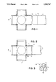
- FIG. 1 is a partial sectional unassembled view of the connector of the construction system and an end of the straight tube beam.
- FIG. 2 is a partial sectional assembled view of the connector of the construction system and the straight tube beam connected to the connector.
- FIG. 3 is a perspective view of the six-cavity connector used in the present construction system.
- FIG. 4 is an assembled view of a structure created with four connectors, two straight molded beams and two curved tube beams.
- FIG. 5 is a view of a straight single cross-member injection molded beam having one joint end connected to a connector of the construction system, shown in cross-section.
- FIG. 6 is an end view of a joint end of a beam.
- FIG. 7 is a view of a curved injection molded beam with two parallel cross-members.
- FIG. 8 is a perspective view of a structure created using straight and curved molded beams and connectors of the construction system.
- FIG. 9 is a perspective view of a structure created using straight molded beams and six-cavity connectors of the construction system.
- FIG. 10 is a cross-sectional view of a structure using straight and curved molded beams and the six-cavity connectors.
- a connector is generally referred to by the numeral 8.
- the body of the straight tube beam is referred to by the numeral 3.
- Tube beams are formed by a central body 3, joint ends 1, and flanges 2.
- the joint ends are continuations of the central body, separated by the flanges.
- the extreme end 4 may be chamfered or rounded to aid insertion of the joint end into the connector.
- FIG. 2 shows the straight tube beam 3, connected to one of the cylinders 11 of the connector.
- the joint end 1 is pushed into the cylinder.
- the cylinder incorporates an interior surface 13 for holding the outer surface of joint end 1 of the tube beam.
- the flanges 2 circumscribe the edges of the beams and are wider than the body and ends of the beams to prevent the beam from overinsertions or pushing through the cylinders 11.
- the flanges may be added at intervals along an extrusion while the tubes are being extruded.
- the flanges may be formed by upsetting the tube in a die or by adding and shrinking or bonding hoops after the tube is formed.
- FIG. 3 is a perspective view of the connector 8.
- the connector has six square panels 12. Each panel incorporates an outwardly extending cylinder 11. Each cylinder holds a joint end of the beams.
- the connectors allow structures to be created by supporting and holding ends of the beams.
- FIG. 4 A small structure formed by connectors 8, straight molded beams 5, and curved tube beams 4, is shown in FIG. 4.
- FIG. 5 shows an injection molded beam 6 with one-single cross-member 14 having one of the joint ends 7 connected to one of the cylinders of the connector.
- the end view of the joint end of the injection molded beam is shown in FIG. 6.
- the joint-ends of the molded beams are of square shape and narrower than the flanges.
- the joint ends contain disks between the flanges and the ends of the beams created to give stability to edges of the beams and to engage the inner walls of the connector cylinder.
- FIG. 7 is a view of a preferred injection molded beam with two parallel cross members.
- a longitudinally end-to-end extending vertical cross member 17 has two parallel cross members 19 extending across the vertical member to form the injection molded beam 15.
- the two parallel cross webs 19 may have small triangular or beaded gussets 20 as shown in FIG. 4.
- the end structure 21 shown in FIG. 7 has an extension 23 of the main member 17.
- a singles cross member 24 jointed in a cruciform relationship, a disc 9 and square flange 10, as shown in the end of FIG. 6.
- the central section 25 of the beam has web tip portions which extend outward in substantially equal distance from where they joint with other webs.
- FIG. 8 A perspective view of a structure construed with connectors and straight and curved molded beams is shown in FIG. 8.
- FIG. 9 shows a perspective view of a structure construed with connectors and straight molded beams.
- FIG. 10 A structure construed with straight and curved molded beams and connectors is shown in FIG. 10.
Abstract
Description
Claims (15)
Priority Applications (1)
| Application Number | Priority Date | Filing Date | Title |
|---|---|---|---|
| US08/002,950 US5282767A (en) | 1993-01-11 | 1993-01-11 | Construction sets with injection molded and extruded tube beams |
Applications Claiming Priority (1)
| Application Number | Priority Date | Filing Date | Title |
|---|---|---|---|
| US08/002,950 US5282767A (en) | 1993-01-11 | 1993-01-11 | Construction sets with injection molded and extruded tube beams |
Publications (1)
| Publication Number | Publication Date |
|---|---|
| US5282767A true US5282767A (en) | 1994-02-01 |
Family
ID=21703338
Family Applications (1)
| Application Number | Title | Priority Date | Filing Date |
|---|---|---|---|
| US08/002,950 Expired - Fee Related US5282767A (en) | 1993-01-11 | 1993-01-11 | Construction sets with injection molded and extruded tube beams |
Country Status (1)
| Country | Link |
|---|---|
| US (1) | US5282767A (en) |
Cited By (37)
| Publication number | Priority date | Publication date | Assignee | Title |
|---|---|---|---|---|
| US5491950A (en) * | 1994-10-18 | 1996-02-20 | Obegi; Joseph | Modular shear panel system |
| US5518434A (en) * | 1994-11-07 | 1996-05-21 | Ziegler; James T. | Snap fit and twistable toy construction modules |
| US5683283A (en) * | 1994-03-18 | 1997-11-04 | Ideal Ideas, Inc. | Construction blocks for extended support structures |
| US5690446A (en) * | 1996-06-18 | 1997-11-25 | Somerville House Books Limited | Connection system for connecting struts to construct three-dimensional structures |
| US5709581A (en) * | 1996-09-24 | 1998-01-20 | Chaos, L.L.C. | Kinetic toy |
| US5785573A (en) * | 1996-09-24 | 1998-07-28 | Chaos, L.L.C. | Kinetic toy |
| WO1998034706A1 (en) * | 1997-02-06 | 1998-08-13 | Mattel, Inc. | Spherical element combination for construction toy set |
| US5803782A (en) * | 1996-08-28 | 1998-09-08 | Selton; Daniel E. | Universal connector |
| US5916006A (en) * | 1994-06-27 | 1999-06-29 | Handsontoys, Inc. | Flexible foam construction toy set |
| US5919072A (en) * | 1997-02-06 | 1999-07-06 | Mattel, Inc. | Construction toy set for assembling a steerable toy vehicle |
| US5924906A (en) * | 1998-02-06 | 1999-07-20 | Mattel, Inc. | Pin connector for construction toy set |
| WO1999037558A1 (en) * | 1998-01-26 | 1999-07-29 | Chengeta, Cuthbert | A connector |
| US6004021A (en) * | 1995-09-28 | 1999-12-21 | Chaos, L.L.C. | Toy system including hardware toy pieces and toy design software for designing and building various toy layouts using the hardware toy pieces |
| USD418549S (en) * | 1998-03-18 | 2000-01-04 | Interlego Ag | Toy building element |
| US6074269A (en) * | 1996-09-24 | 2000-06-13 | Choas, L.L.C. | Kinetic toy |
| US6286283B1 (en) | 1996-11-21 | 2001-09-11 | Steve Kessler | Modular structural system |
| US6622447B1 (en) | 1996-11-21 | 2003-09-23 | Steven Crawford Kessler | Modular hub and strut structural system |
| US20040253902A1 (en) * | 2003-06-16 | 2004-12-16 | Diana Sinisi | Building toy set |
| US20050070202A1 (en) * | 2003-09-29 | 2005-03-31 | Mendel Nancy W. | Hoop-type amusement device |
| US20060272110A1 (en) * | 2005-05-12 | 2006-12-07 | De La Chevrotiere Alexandre | Moment-Resisting Joint and System |
| US20060278591A1 (en) * | 2005-06-08 | 2006-12-14 | Tippets Michael A | First in, first out, gravity-feed can organizer |
| US20070026759A1 (en) * | 2005-07-29 | 2007-02-01 | Greene Plastics Corporation | Construction system |
| US7316598B1 (en) | 2005-08-17 | 2008-01-08 | Lock Keith S | Toy construction set |
| US20080139040A1 (en) * | 2005-04-06 | 2008-06-12 | Industrial Technology Research Institute | Assembly apparatus |
| US20100083605A1 (en) * | 2003-04-24 | 2010-04-08 | Ulrich Wallner | System, method and device for producing a supporting framework or rigid girder structure |
| US20100221976A1 (en) * | 2007-09-19 | 2010-09-02 | Eliyahu Weber | Toy building construction set |
| US20110078913A1 (en) * | 2009-10-06 | 2011-04-07 | Schneider James C | Scale coupling system |
| US20110197378A1 (en) * | 2008-10-06 | 2011-08-18 | De La Chevrotiere Alexandre | Structural assemblies for constructing bridges and other structures |
| US8382548B2 (en) | 2009-02-13 | 2013-02-26 | Mattel, Inc. | Toy building blocks |
| US20130244530A1 (en) * | 2012-03-19 | 2013-09-19 | John Renfro | Foam construction toy |
| US8632375B1 (en) * | 2009-07-15 | 2014-01-21 | Sean Mertes | Toy fort apparatus and methods |
| US8708765B2 (en) | 2011-11-17 | 2014-04-29 | Fort Magic, Llc | Kit for constructing a play structure |
| US9283491B2 (en) | 2011-11-17 | 2016-03-15 | Fort Magic, Llc | Kit for constructing a play structure |
| US9498703B2 (en) | 2013-03-13 | 2016-11-22 | Stat Ventures, Inc. | Assembly kit for three dimensional works |
| US20180036631A1 (en) * | 2015-02-17 | 2018-02-08 | Murray HEASMAN | Apparatus for playing a game |
| US20180133614A1 (en) * | 2016-11-11 | 2018-05-17 | Joseph Kendall | Elastomeric block system for multi-modal play |
| US11278821B2 (en) * | 2017-02-16 | 2022-03-22 | Jason R. Brain | Modular toy block system |
Citations (29)
| Publication number | Priority date | Publication date | Assignee | Title |
|---|---|---|---|---|
| US144124A (en) * | 1873-10-28 | Improvement in toy building-blocks | ||
| CA113975A (en) * | 1908-08-14 | 1908-09-08 | Edward Ernest Barrett | Coal moving apparatus |
| US1216840A (en) * | 1915-10-29 | 1917-02-20 | Embossing Company | Toy building-block. |
| US1281856A (en) * | 1916-01-24 | 1918-10-15 | Slade & Miller Company | Toy blocks. |
| GB176013A (en) * | 1919-04-05 | 1922-03-09 | William Henry Williams | Improvements in or relating to constructional toys |
| US2147373A (en) * | 1935-11-18 | 1939-02-14 | Wilbur G Laird | Constructional toy |
| DE825518C (en) * | 1950-02-10 | 1951-12-20 | Willy Gruenwald | Building game |
| CH281162A (en) * | 1950-01-26 | 1952-02-29 | Waldis Charles | Wooden construction kit. |
| US2799119A (en) * | 1954-11-22 | 1957-07-16 | Lionel Corp | Coaling stations for toy railroads |
| GB798278A (en) * | 1955-06-07 | 1958-07-16 | Harris And Sheldon Display Ltd | Improved connecting means for rods, bars or the like, for display purposes |
| US2885822A (en) * | 1956-06-29 | 1959-05-12 | Richard A Onanian | Construction set |
| US2937471A (en) * | 1958-10-17 | 1960-05-24 | Parisi Pasquale | Construction toy |
| US3168793A (en) * | 1961-11-20 | 1965-02-09 | Kelton Corp Ltd | Construction toy means for locking a horizontal i-beam between two detachably joinedvertical column members |
| US3528079A (en) * | 1968-01-02 | 1970-09-08 | Standard Toykraft Inc | Paper doll having combined ornament and fastening device |
| US3545123A (en) * | 1963-08-26 | 1970-12-08 | Hermann E Muller | Cruciform male and female connectors |
| GB1238975A (en) * | 1968-11-14 | 1971-07-14 | ||
| US3638352A (en) * | 1969-02-03 | 1972-02-01 | Interlego Ag | Splined shaft and wheel retained thereon by spring and hub element |
| US3640018A (en) * | 1970-05-18 | 1972-02-08 | Stanley Light | Knockdown structural toys |
| DE2129763A1 (en) * | 1971-06-16 | 1972-12-21 | Artur Fischer | Kit of cuboid or prismatic learning modules |
| DE2154544A1 (en) * | 1971-11-03 | 1973-05-10 | Dieter Dorsch | PLAY BLOCK IN CUBE SHAPE |
| US3890022A (en) * | 1974-09-03 | 1975-06-17 | Howard R Moon | Corner fitting |
| US3940142A (en) * | 1974-11-29 | 1976-02-24 | Ideal Toy Corporation | Fold up die construction |
| US4003144A (en) * | 1975-07-11 | 1977-01-18 | Damon Corporation | Educational block with replaceable chip |
| DE2638969A1 (en) * | 1975-09-10 | 1977-03-17 | Hermann Mueller | TOY KIT |
| US4129975A (en) * | 1977-03-09 | 1978-12-19 | Matrix Toys, Inc. | Construction set having clip fasteners |
| US4170082A (en) * | 1977-02-28 | 1979-10-09 | Calvin Freedman | Modular connectors for cylindrical elements |
| US4484407A (en) * | 1983-03-28 | 1984-11-27 | Brio Toy Ab | Connection element for assembling toys |
| US5061219A (en) * | 1990-12-11 | 1991-10-29 | Magic Mold Corporation | Construction toy |
| US5120253A (en) * | 1991-03-13 | 1992-06-09 | Gelardi John A | Connectors for forming structures |
-
1993
- 1993-01-11 US US08/002,950 patent/US5282767A/en not_active Expired - Fee Related
Patent Citations (29)
| Publication number | Priority date | Publication date | Assignee | Title |
|---|---|---|---|---|
| US144124A (en) * | 1873-10-28 | Improvement in toy building-blocks | ||
| CA113975A (en) * | 1908-08-14 | 1908-09-08 | Edward Ernest Barrett | Coal moving apparatus |
| US1216840A (en) * | 1915-10-29 | 1917-02-20 | Embossing Company | Toy building-block. |
| US1281856A (en) * | 1916-01-24 | 1918-10-15 | Slade & Miller Company | Toy blocks. |
| GB176013A (en) * | 1919-04-05 | 1922-03-09 | William Henry Williams | Improvements in or relating to constructional toys |
| US2147373A (en) * | 1935-11-18 | 1939-02-14 | Wilbur G Laird | Constructional toy |
| CH281162A (en) * | 1950-01-26 | 1952-02-29 | Waldis Charles | Wooden construction kit. |
| DE825518C (en) * | 1950-02-10 | 1951-12-20 | Willy Gruenwald | Building game |
| US2799119A (en) * | 1954-11-22 | 1957-07-16 | Lionel Corp | Coaling stations for toy railroads |
| GB798278A (en) * | 1955-06-07 | 1958-07-16 | Harris And Sheldon Display Ltd | Improved connecting means for rods, bars or the like, for display purposes |
| US2885822A (en) * | 1956-06-29 | 1959-05-12 | Richard A Onanian | Construction set |
| US2937471A (en) * | 1958-10-17 | 1960-05-24 | Parisi Pasquale | Construction toy |
| US3168793A (en) * | 1961-11-20 | 1965-02-09 | Kelton Corp Ltd | Construction toy means for locking a horizontal i-beam between two detachably joinedvertical column members |
| US3545123A (en) * | 1963-08-26 | 1970-12-08 | Hermann E Muller | Cruciform male and female connectors |
| US3528079A (en) * | 1968-01-02 | 1970-09-08 | Standard Toykraft Inc | Paper doll having combined ornament and fastening device |
| GB1238975A (en) * | 1968-11-14 | 1971-07-14 | ||
| US3638352A (en) * | 1969-02-03 | 1972-02-01 | Interlego Ag | Splined shaft and wheel retained thereon by spring and hub element |
| US3640018A (en) * | 1970-05-18 | 1972-02-08 | Stanley Light | Knockdown structural toys |
| DE2129763A1 (en) * | 1971-06-16 | 1972-12-21 | Artur Fischer | Kit of cuboid or prismatic learning modules |
| DE2154544A1 (en) * | 1971-11-03 | 1973-05-10 | Dieter Dorsch | PLAY BLOCK IN CUBE SHAPE |
| US3890022A (en) * | 1974-09-03 | 1975-06-17 | Howard R Moon | Corner fitting |
| US3940142A (en) * | 1974-11-29 | 1976-02-24 | Ideal Toy Corporation | Fold up die construction |
| US4003144A (en) * | 1975-07-11 | 1977-01-18 | Damon Corporation | Educational block with replaceable chip |
| DE2638969A1 (en) * | 1975-09-10 | 1977-03-17 | Hermann Mueller | TOY KIT |
| US4170082A (en) * | 1977-02-28 | 1979-10-09 | Calvin Freedman | Modular connectors for cylindrical elements |
| US4129975A (en) * | 1977-03-09 | 1978-12-19 | Matrix Toys, Inc. | Construction set having clip fasteners |
| US4484407A (en) * | 1983-03-28 | 1984-11-27 | Brio Toy Ab | Connection element for assembling toys |
| US5061219A (en) * | 1990-12-11 | 1991-10-29 | Magic Mold Corporation | Construction toy |
| US5120253A (en) * | 1991-03-13 | 1992-06-09 | Gelardi John A | Connectors for forming structures |
Cited By (54)
| Publication number | Priority date | Publication date | Assignee | Title |
|---|---|---|---|---|
| US5683283A (en) * | 1994-03-18 | 1997-11-04 | Ideal Ideas, Inc. | Construction blocks for extended support structures |
| US5916006A (en) * | 1994-06-27 | 1999-06-29 | Handsontoys, Inc. | Flexible foam construction toy set |
| US5491950A (en) * | 1994-10-18 | 1996-02-20 | Obegi; Joseph | Modular shear panel system |
| US5518434A (en) * | 1994-11-07 | 1996-05-21 | Ziegler; James T. | Snap fit and twistable toy construction modules |
| US6004021A (en) * | 1995-09-28 | 1999-12-21 | Chaos, L.L.C. | Toy system including hardware toy pieces and toy design software for designing and building various toy layouts using the hardware toy pieces |
| US5690446A (en) * | 1996-06-18 | 1997-11-25 | Somerville House Books Limited | Connection system for connecting struts to construct three-dimensional structures |
| US5803782A (en) * | 1996-08-28 | 1998-09-08 | Selton; Daniel E. | Universal connector |
| US5785573A (en) * | 1996-09-24 | 1998-07-28 | Chaos, L.L.C. | Kinetic toy |
| US5908343A (en) * | 1996-09-24 | 1999-06-01 | Rothbarth; James N. | Kinetic toy |
| US5709581A (en) * | 1996-09-24 | 1998-01-20 | Chaos, L.L.C. | Kinetic toy |
| US6074269A (en) * | 1996-09-24 | 2000-06-13 | Choas, L.L.C. | Kinetic toy |
| US6622447B1 (en) | 1996-11-21 | 2003-09-23 | Steven Crawford Kessler | Modular hub and strut structural system |
| US6286283B1 (en) | 1996-11-21 | 2001-09-11 | Steve Kessler | Modular structural system |
| US5823843A (en) * | 1997-02-06 | 1998-10-20 | Pohlman; Joe K. | Spherical element combination for construction toy set |
| US5919072A (en) * | 1997-02-06 | 1999-07-06 | Mattel, Inc. | Construction toy set for assembling a steerable toy vehicle |
| WO1998034706A1 (en) * | 1997-02-06 | 1998-08-13 | Mattel, Inc. | Spherical element combination for construction toy set |
| WO1999037558A1 (en) * | 1998-01-26 | 1999-07-29 | Chengeta, Cuthbert | A connector |
| US5924906A (en) * | 1998-02-06 | 1999-07-20 | Mattel, Inc. | Pin connector for construction toy set |
| USD418549S (en) * | 1998-03-18 | 2000-01-04 | Interlego Ag | Toy building element |
| US8387330B2 (en) * | 2003-04-24 | 2013-03-05 | Ulrich Wallner | System, method and device for producing a supporting framework or rigid girder structure |
| US20100083605A1 (en) * | 2003-04-24 | 2010-04-08 | Ulrich Wallner | System, method and device for producing a supporting framework or rigid girder structure |
| US20040253902A1 (en) * | 2003-06-16 | 2004-12-16 | Diana Sinisi | Building toy set |
| US20050070202A1 (en) * | 2003-09-29 | 2005-03-31 | Mendel Nancy W. | Hoop-type amusement device |
| US6966814B2 (en) * | 2003-09-29 | 2005-11-22 | Mendel Nancy W | Hoop-type amusement device |
| US20080139040A1 (en) * | 2005-04-06 | 2008-06-12 | Industrial Technology Research Institute | Assembly apparatus |
| US7882586B2 (en) | 2005-05-12 | 2011-02-08 | De La Chevrotiere Alexandre | Moment-resisting joint and system |
| US8590084B2 (en) | 2005-05-12 | 2013-11-26 | Alexandre de la Chevrotière | Moment-resisting joint and system |
| US7568253B2 (en) * | 2005-05-12 | 2009-08-04 | De La Chevrotiere Alexandre | Moment-resisting joint and system |
| US20090266024A1 (en) * | 2005-05-12 | 2009-10-29 | De La Chevrotiere Alexandre | Moment-resisting joint and system |
| US20060272110A1 (en) * | 2005-05-12 | 2006-12-07 | De La Chevrotiere Alexandre | Moment-Resisting Joint and System |
| US20110146193A1 (en) * | 2005-05-12 | 2011-06-23 | De La Chevrotiere Alexandre | Moment-resisting joint and system |
| US20060278591A1 (en) * | 2005-06-08 | 2006-12-14 | Tippets Michael A | First in, first out, gravity-feed can organizer |
| US7374468B2 (en) | 2005-07-29 | 2008-05-20 | Greene Plastics Corporation | Construction system |
| US20070026759A1 (en) * | 2005-07-29 | 2007-02-01 | Greene Plastics Corporation | Construction system |
| US7316598B1 (en) | 2005-08-17 | 2008-01-08 | Lock Keith S | Toy construction set |
| US20100221976A1 (en) * | 2007-09-19 | 2010-09-02 | Eliyahu Weber | Toy building construction set |
| US8469764B2 (en) * | 2007-09-19 | 2013-06-25 | Eliyahu Weber | Toy building construction set |
| US8667633B2 (en) | 2008-10-06 | 2014-03-11 | Alexandre de la Chevrotiere | Structural assemblies for constructing bridges and other structures |
| US11035086B2 (en) | 2008-10-06 | 2021-06-15 | Alexandre de la Chevrotiere | Structural assemblies for constructing bridges and other structures |
| US20110197378A1 (en) * | 2008-10-06 | 2011-08-18 | De La Chevrotiere Alexandre | Structural assemblies for constructing bridges and other structures |
| US8961259B2 (en) | 2009-02-13 | 2015-02-24 | Mattel, Inc. | Toy building blocks |
| US8382548B2 (en) | 2009-02-13 | 2013-02-26 | Mattel, Inc. | Toy building blocks |
| US8632375B1 (en) * | 2009-07-15 | 2014-01-21 | Sean Mertes | Toy fort apparatus and methods |
| US8359759B2 (en) * | 2009-10-06 | 2013-01-29 | Schneider James C | Scale coupling system |
| US20110078913A1 (en) * | 2009-10-06 | 2011-04-07 | Schneider James C | Scale coupling system |
| US9283491B2 (en) | 2011-11-17 | 2016-03-15 | Fort Magic, Llc | Kit for constructing a play structure |
| US8708765B2 (en) | 2011-11-17 | 2014-04-29 | Fort Magic, Llc | Kit for constructing a play structure |
| US20130244530A1 (en) * | 2012-03-19 | 2013-09-19 | John Renfro | Foam construction toy |
| US9498703B2 (en) | 2013-03-13 | 2016-11-22 | Stat Ventures, Inc. | Assembly kit for three dimensional works |
| US20180036631A1 (en) * | 2015-02-17 | 2018-02-08 | Murray HEASMAN | Apparatus for playing a game |
| US10245503B2 (en) * | 2015-02-17 | 2019-04-02 | Murray HEASMAN | Apparatus for playing a game |
| US20180133614A1 (en) * | 2016-11-11 | 2018-05-17 | Joseph Kendall | Elastomeric block system for multi-modal play |
| US11278821B2 (en) * | 2017-02-16 | 2022-03-22 | Jason R. Brain | Modular toy block system |
| US11779855B2 (en) | 2017-02-16 | 2023-10-10 | Jason R. Brain | Modular toy block system |
Similar Documents
| Publication | Publication Date | Title |
|---|---|---|
| US5282767A (en) | Construction sets with injection molded and extruded tube beams | |
| US4608799A (en) | Building block system | |
| US3648404A (en) | Connector unit having radial arms for straight or angular connections | |
| JP3004661B2 (en) | Building blocks consisting of built-in building blocks for assembling in layers | |
| EP1027118B1 (en) | Panels for construction toy set | |
| US6450853B1 (en) | Building block system, especially a toy building block system | |
| US6592421B1 (en) | Totipotent hub for construction toy system | |
| US3594940A (en) | Assembly toy set | |
| US5097643A (en) | Interlocking structural members with edge connectors | |
| EP0375544B1 (en) | Toy construction assembly | |
| US5097645A (en) | Space frame system | |
| US5611187A (en) | Construction system | |
| CA2202602A1 (en) | Constructional pieces with deformable joints | |
| GB2119471A (en) | Structural couplings | |
| EP1022040A3 (en) | A system of elements for the composition of static or dynamic constructions | |
| US5918999A (en) | Geometric spacial frame assembly | |
| US4585422A (en) | Toy construction kit | |
| US4484429A (en) | Connector for a framework structure | |
| US4143481A (en) | Educational toy | |
| GB2077879A (en) | Structural joint | |
| EP1064061A1 (en) | A toy construction system | |
| EP1207951B1 (en) | An assembly kit for creating three-dimensional toy structures | |
| US3704541A (en) | Tubular maze toys | |
| HU183963B (en) | Nodal structure suitable for collapsible compacting plates beingin cross direction considering to one another | |
| US4299050A (en) | Construction toy and container |
Legal Events
| Date | Code | Title | Description |
|---|---|---|---|
| FPAY | Fee payment |
Year of fee payment: 4 |
|
| FPAY | Fee payment |
Year of fee payment: 8 |
|
| AS | Assignment |
Owner name: SAGOMA PLASTICS CORPORATION, MAINE Free format text: ASSIGNMENT OF ASSIGNORS INTEREST;ASSIGNOR:GELARDI, JOHN A.;REEL/FRAME:012177/0328 Effective date: 20010919 |
|
| REMI | Maintenance fee reminder mailed | ||
| AS | Assignment |
Owner name: GDP, LLC, MAINE Free format text: ASSIGNMENT OF ASSIGNORS INTEREST;ASSIGNOR:SAGOMA PLASTICS CORPORATION;REEL/FRAME:016914/0806 Effective date: 20050506 |
|
| LAPS | Lapse for failure to pay maintenance fees | ||
| STCH | Information on status: patent discontinuation |
Free format text: PATENT EXPIRED DUE TO NONPAYMENT OF MAINTENANCE FEES UNDER 37 CFR 1.362 |
|
| FP | Lapsed due to failure to pay maintenance fee |
Effective date: 20060201 |