US5273152A - Apparatus for positioning articles - Google Patents
Apparatus for positioning articles Download PDFInfo
- Publication number
- US5273152A US5273152A US07/870,464 US87046492A US5273152A US 5273152 A US5273152 A US 5273152A US 87046492 A US87046492 A US 87046492A US 5273152 A US5273152 A US 5273152A
- Authority
- US
- United States
- Prior art keywords
- center spacing
- support members
- parisons
- grooves
- workstation
- Prior art date
- Legal status (The legal status is an assumption and is not a legal conclusion. Google has not performed a legal analysis and makes no representation as to the accuracy of the status listed.)
- Expired - Lifetime
Links
Images


Classifications
-
- B—PERFORMING OPERATIONS; TRANSPORTING
- B65—CONVEYING; PACKING; STORING; HANDLING THIN OR FILAMENTARY MATERIAL
- B65G—TRANSPORT OR STORAGE DEVICES, e.g. CONVEYORS FOR LOADING OR TIPPING, SHOP CONVEYOR SYSTEMS OR PNEUMATIC TUBE CONVEYORS
- B65G47/00—Article or material-handling devices associated with conveyors; Methods employing such devices
- B65G47/22—Devices influencing the relative position or the attitude of articles during transit by conveyors
- B65G47/26—Devices influencing the relative position or the attitude of articles during transit by conveyors arranging the articles, e.g. varying spacing between individual articles
- B65G47/30—Devices influencing the relative position or the attitude of articles during transit by conveyors arranging the articles, e.g. varying spacing between individual articles during transit by a series of conveyors
- B65G47/32—Applications of transfer devices
-
- B—PERFORMING OPERATIONS; TRANSPORTING
- B29—WORKING OF PLASTICS; WORKING OF SUBSTANCES IN A PLASTIC STATE IN GENERAL
- B29C—SHAPING OR JOINING OF PLASTICS; SHAPING OF MATERIAL IN A PLASTIC STATE, NOT OTHERWISE PROVIDED FOR; AFTER-TREATMENT OF THE SHAPED PRODUCTS, e.g. REPAIRING
- B29C49/00—Blow-moulding, i.e. blowing a preform or parison to a desired shape within a mould; Apparatus therefor
- B29C49/42—Component parts, details or accessories; Auxiliary operations
- B29C49/4205—Handling means, e.g. transfer, loading or discharging means
- B29C49/42113—Means for manipulating the objects' position or orientation
- B29C49/42121—Changing the center-center distance
- B29C49/42122—Adapting to blow-mould cavity center-center distance
-
- B—PERFORMING OPERATIONS; TRANSPORTING
- B65—CONVEYING; PACKING; STORING; HANDLING THIN OR FILAMENTARY MATERIAL
- B65B—MACHINES, APPARATUS OR DEVICES FOR, OR METHODS OF, PACKAGING ARTICLES OR MATERIALS; UNPACKING
- B65B21/00—Packaging or unpacking of bottles
- B65B21/02—Packaging or unpacking of bottles in or from preformed containers, e.g. crates
- B65B21/14—Introducing or removing groups of bottles, for filling or emptying containers in one operation
- B65B21/18—Introducing or removing groups of bottles, for filling or emptying containers in one operation using grippers engaging bottles, e.g. bottle necks
- B65B21/20—Introducing or removing groups of bottles, for filling or emptying containers in one operation using grippers engaging bottles, e.g. bottle necks with means for varying spacing of bottles
-
- B—PERFORMING OPERATIONS; TRANSPORTING
- B65—CONVEYING; PACKING; STORING; HANDLING THIN OR FILAMENTARY MATERIAL
- B65G—TRANSPORT OR STORAGE DEVICES, e.g. CONVEYORS FOR LOADING OR TIPPING, SHOP CONVEYOR SYSTEMS OR PNEUMATIC TUBE CONVEYORS
- B65G47/00—Article or material-handling devices associated with conveyors; Methods employing such devices
- B65G47/74—Feeding, transfer, or discharging devices of particular kinds or types
- B65G47/90—Devices for picking-up and depositing articles or materials
- B65G47/907—Devices for picking-up and depositing articles or materials with at least two picking-up heads
Definitions
- the present invention relates to an apparatus for positioning articles having a center spacing, and especially for positioning pressure molded plastic articles that incorporates a variety of interconnected workstations, and, more particularly, to an apparatus for altering the center spacing of articles between various connected workstations.
- parisons are expanded to form bottles.
- a larger center spacing is required at these workstations to provide room for the circumferential expansion of the parisons.
- the primary object of the present invention to provide an apparatus whereby the center spacing of articles or parisons to be treated can be altered in two directions.
- an apparatus comprising, according to the invention, an upstream workstation for treating a plurality of articles, preferably plastic articles, spaced from each other at a first center spacing, a downstream workstation for said articles spaced from each other at a second center spacing which is preferably larger than the first center spacing, and means for altering the center spacing of the articles in two directions from the first center spacing of the upstream workstation to the second center spacing of the downstream workstation, said means for altering the center spacing comprising a plate means having a plurality of grooves, and a plurality of support members mounted slidably on the plate means, said support members being guided in the grooves of the plate means and intersecting at an angle with the grooves of the plate means.
- the support means are preferably provided with longitudinal tracks therein.
- the apparatus further comprises a plurality of grippers suitable for holding the articles equal in number to a predetermined number of articles to be processed per cycle, the grippers being slidably disposed on the support members at the points of intersection with the grooves of the plate means and the tracks of the support members, whereby displacement of the support members relative to the plate means results in two directional spreading of the grippers from the first center spacing to the second center spacing.
- the angle of intersection between the grooves of the plate means and the tracks of the support members is predetermined to provide two directional spreading of the articles responsive to motion of the support members only.
- a plurality of additional support members are mounted slidably on the plate means, at least some of the grooves of the plate means being located on the additional support members, said additional support members being essentially perpendicular to the tracks of the support members, whereby the support members and the additional support members are operative to alter the center spacing of the articles independently in two directions.
- FIG. 1 is a block diagram demonstrating the spreading of articles in one direction as per the prior art
- FIG. 2 is a block diagram demonstrating the spreading of articles in two directions according to the invention
- FIG. 3 is a side elevational view a preferred embodiment of the invention.
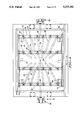
- FIG. 4 is a top view of the apparatus according to a preferred embodiment of the invention, with additional features being shown in dashed lines;
- FIG. 5 is a top view of an alternate embodiment of an apparatus according to the invention, also with additional features of the invention being shown in dashed lines;
- FIG. 6 is a top view of still another preferred embodiment of the apparatus according to the invention.
- FIG. 7 is a side elevational view of the preferred embodiment of FIG. 6.
- FIG. 8 is a cross section of an anti-rotation device according to the invention.
- FIGS. 1 and 2 the operation of the prior art and the present invention are schematically depicted.
- spacing of the articles can be accomplished in one direction, as shown by the arrow (A) in FIG. 1.
- the non-altered direction as shown by the arrow (B) spacing must be sufficient at upstream workstation (10) to accommodate the largest possible spacing required by any workstation, as at downstream workstation (12).
- the apparatus according to the present invention is used to alter the center spacing between an upstream workstation (10) and the downstream workstation (12) in two directions. As shown in FIG.
- the invention may advantageously be used to increase the two directional center spacing of work pieces from a close spacing as shown in the upstream workstation (10) to a wider center spacing as shown in the downstream workstation (12).
- spacing is increased in two directions (X, Y).
- Such a function is useful in any situation where it is desirable to reposition or alter the spacing between work pieces during the operation of a machine, and has particular use when the upstream workstation (10) is an injection molding station and the downstream workstation (12) is a blow molding workstation.
- the injection molding is preferably carried out at a close spacing, for example to help avoid problems caused by the flow of molten plastic over greater distances.
- a narrower spacing at the injection molding workstation is also desirable for the purpose of reducing the space occupied by this portion of the machine, and reducing the size of the platen used in this procedure.
- the articles are to be circumferentially expanded and must therefore be spaced from each other at a distance sufficient to accommodate the expansion of the articles.
- the center spacing of the blow molding stations must generally be significantly larger than the center spacing at the injection molding workstation in two directions.
- the articles or work pieces to which the invention is directed are typically parisons (20) which are formed at an injection molding workstation in a conventional manner as an intermediate step in manufacturing plastic bottles.
- the parisons (20) are subsequently expanded at a blow molding workstation to obtain the final product, also in a conventional manner.
- the transport of parisons (20) may be conducted by any desired means, as through grippers (22) which are generally depicted in FIG. 3, but for which any type of gripping means which may be known in the art may be substituted.
- the grippers (22) or desired holding means are laterally repositioned in two directions as shown in FIG. 2 to place the parisons (20) in their intended locations for the blow molding operation.
- the grippers (22) are preferably suspended from a plate means preferably comprising a base plate (24) which may be mounted on any conventional mounting means, not shown, to facilitate movement to and from the desired workstations in the machine.
- the base plate (24) may be in the form of a generally flat plate and is provided with grooves (28) extending therethrough.
- a plurality of support members (30) or pushers (shown in phantom) are slidably mounted on the base plate (24).
- the slidable mounting of the support members (30) may preferably be achieved through disposing each end (32), (34) of the support members (30) in brackets (36) mounted to the base plate (24) and positioned to provide the desired sliding motion of the support members (30) along the base plate.
- Each support member (30) has at least one track (38) extending therethrough and intersecting the grooves (28) of the base plate (24).
- the grippers (22) (shown in phantom) are mounted on the support members at the points of intersection of the grooves (28) of the base plate (24) and the tracks (38) of the support members (30), with the grippers (22) sliding along grooves (28) upon movement of the support members (30). Therefore, lateral spreading of the support members (30) will result in angular displacement of the grippers (22) and parison held thereon along the grooves (28) of the base plate (24) resulting in altering the center spacing of the articles held by grippers (22) in both the (X) and (Y) directions as shown in FIG. 4, with the (X) direction being essentially perpendicular to the support members and the (Y) direction being essentially parallel to the support members.
- the grippers (22) can be conveyed from a first center spacing, depicted by the inner ends (40) of the grooves (28) (the closed position) to a larger second center spacing (the open position shown in FIG. 4) defined by the outer ends (42) of the grooves (28). It should be noted that a center spacing of any desired distance between the inner ends (40) and outer ends (42) can also be achieved.
- the lateral motion of the support members (30) which imparts the desired spreading of the grippers (22) can be provided through any motive means, e.g., fluid cylinders (26), as shown in FIG. 4.
- the support members (30) preferably have a length sufficient to accommodate the maximum spacing of the articles, and are selected in number corresponding to the number of rows of articles to be treated during each cycle of the machine.
- Each track (38) extending through a support member (30) may preferably extend the entire length of the support member (30).
- the grooves (28) of the base plate (24) can be disposed at any angle to the tracks (38) of the support members (30) in order to achieve the desired motion of the grippers (22), generally from 10° to 90° , inclusive.
- the orientation or divergence of the grooves (28) as located in the base plate (24) can be selected to increase or decrease the resulting article spacing in both the (X) and (Y) directions (as depicted by the arrows (X, Y) in FIG. 4).
- the means for altering the center spacing is operative to achieve an angular displacement from a first center spacing to a second center spacing.
- each support member (30) has a plurality of tracks (38a) extending therethrough.
- Each track (38a) of the plurality of tracks extends only so far as is necessary to accommodate the desired motion of the gripper (22) mounted on the support members.
- FIG. 5 shows the grippers (22) in their closed position, with the grippers (22) shown in phantom representing the open position.
- spacing means cooperating with the support members can be used to accurately position the support members, as pins (44a) can be used to facilitate spreading of the support members (30).
- a spreading force (by means not shown) imparted to the outermost support members (30) causes the pins (44a) to catch at desired intervals and drag subsequent support members into position.
- the pins (44a) are preferably threadedly mounted in the support member (30) so that the desired interval between support members (30) can be adjusted.
- FIG. 6 another alternate embodiment of the invention will be described.
- the tracks (38a) of the support members (30) may be positioned perpendicular to the grooves (28) of the base plate (24). Further, some or all of the grooves (28) of the base plate (24) may be located on additional support members (48) slidably mounted to the base plate (24) essentially perpendicular to the support members.
- the support members (30) and the additional support members (48) are slidably mounted to the base plate (24) so as to be spaceable perpendicularly to each other.
- the grippers (22) are mounted on the support members at the points of intersection of the grooves (28) with the tracks (38a) as described above.
- the tracks (38a) of the support members (30) accommodate motion of the grippers (22) in the (Y) direction while the grooves (28) in the base plate (24) and in the additional support members (48) accommodate motion of the grippers (22) in the (X) direction.
- two motive means are also preferably provided as schematically depicted in FIG. 6, with motive means (52) operating support members (48) and motive means (53) operating support members (30).
- These motive means can be of any type as are known in the art.
- the support members (30) are displaceable along the (X) direction through a series of scissor-levers (50) connected to the support members (30).
- the scissor-levers (50) can be extended and withdrawn in order to impart the desired spacing motion to the support members (30).
- additional support members (48) are displaceable along the (y) direction.
- the additional support members (48) may be actuated by a piston and rod structure (52) to obtain the desired motion of the additional support members (48) in the (Y) direction.
- these motive means are given by way of example only, and that numerous other conventional motive means could suitably be substituted therefor.
- the embodiment shown therein provides movement in the (Y) direction of the outside rows only via additional support members (48). It should be understood, however, that any number of additional support members (48) could be present, and any or all of these could be actuated by the piston and rod structure (52).
- the embodiment of FIG. 6 shows an intermediate stage, with support members 30 in the open or spaced apart position and additional support members (48) in the closed or spaced together position.
- the slidable junction between the grippers (22), grooves (28) of the base plate (24), and tracks (38) or (38a) of the support members (30) are preferably established through anti-rotation mechanisms (54).
- the anti-rotation mechanisms (54) prevent rotation of the grippers (22) and their carried parisons (20) which would otherwise be imparted by the interaction of the grooves (28) and tracks (38) with the shaft (56) of the gripper (22). Such rotation is undesirable as it may adversely affect ultimate positioning of the parisons (20).
- FIG. 8 shows the shaft (56) of the gripper (22) mounted inside an inner sleeve (58).
- the inner sleeve (58) carries a plurality of bearing members or needles (60) which allow the free rotation of an outer sleeve (62).
- the outer sleeve (62) is the element of the device which is in contact with the grooves (28) and tracks (38).
- the shaft (56) and inner sleeve (58) may be fixed against rotation through any means known in the art, such as, for example, a connection to a slide means affixed to the support member (30), thereby preventing rotation of the article held by the gripper while permitting free rotation of outer sleeve (62).
- Such an anti-rotation mechanism (54) could be usefully employed in any of the aforedescribed embodiments.
- the apparatus according to the present invention is preferably used for adjusting the center spacing in two directions between an injection molding workstation having a narrow center spacing of workpieces and a blow molding workstation having an increased center spacing between the workpieces. It should be noted, however, that the invention may be usefully disposed for operation between any workstations which require an alteration in two directions of the center spacing of the workpieces. Further, various other workstations could obviously be located between the apparatus according to the invention and any of the workstations requiring the modified center spacing.
- the apparatus according to the invention provides two-directional repositioning of the center spacing of the workpieces, which results in greater operating efficiency and more efficient usage of space in a machine employing the device according to the invention.
Landscapes
- Engineering & Computer Science (AREA)
- Mechanical Engineering (AREA)
- Manufacturing & Machinery (AREA)
- Blow-Moulding Or Thermoforming Of Plastics Or The Like (AREA)
Abstract
Description
Claims (3)
Priority Applications (1)
| Application Number | Priority Date | Filing Date | Title |
|---|---|---|---|
| US07/870,464 US5273152A (en) | 1992-04-17 | 1992-04-17 | Apparatus for positioning articles |
Applications Claiming Priority (1)
| Application Number | Priority Date | Filing Date | Title |
|---|---|---|---|
| US07/870,464 US5273152A (en) | 1992-04-17 | 1992-04-17 | Apparatus for positioning articles |
Publications (1)
| Publication Number | Publication Date |
|---|---|
| US5273152A true US5273152A (en) | 1993-12-28 |
Family
ID=25355437
Family Applications (1)
| Application Number | Title | Priority Date | Filing Date |
|---|---|---|---|
| US07/870,464 Expired - Lifetime US5273152A (en) | 1992-04-17 | 1992-04-17 | Apparatus for positioning articles |
Country Status (1)
| Country | Link |
|---|---|
| US (1) | US5273152A (en) |
Cited By (25)
| Publication number | Priority date | Publication date | Assignee | Title |
|---|---|---|---|---|
| EP0768254A1 (en) * | 1995-10-16 | 1997-04-16 | Soremartec S.A. | A pick-up device |
| US5643619A (en) * | 1995-12-18 | 1997-07-01 | Electra Form, Inc. | Article repositioning apparatus for an injection stretch blow molding machine |
| US5653934A (en) * | 1995-05-05 | 1997-08-05 | Electra Form, Inc. | Molded part take-out apparatus |
| NL1009652C2 (en) * | 1998-07-14 | 2000-01-18 | Ebm Techniek Bv | Device for engaging with products. |
| US6068317A (en) * | 1997-11-08 | 2000-05-30 | Mirae Corporation | Device for adjusting space between chip in semiconductor chip tester |
| EP1231145A1 (en) * | 2001-02-13 | 2002-08-14 | OMA S.r.l. | Manipulating head for cartoning machines |
| US20020142065A1 (en) * | 2001-03-29 | 2002-10-03 | Alkam S.R.L. | Device for treating preforms to obtain containers made of plastics |
| US6589008B1 (en) * | 2001-10-02 | 2003-07-08 | Advanced Manufacturing Technology | Container handling device and method |
| US20030168873A1 (en) * | 2000-07-12 | 2003-09-11 | Mario Lanfranchi | Head for transferring containers, in particular bottles, within a palletiser |
| US20060213750A1 (en) * | 2005-03-24 | 2006-09-28 | Siemens Aktiengesellschaft | Method of equally spacing items in article handling systems |
| WO2008114182A1 (en) * | 2007-03-22 | 2008-09-25 | The Procter & Gamble Company | Apparatus and method for producing containers |
| US20090297301A1 (en) * | 2006-07-01 | 2009-12-03 | Techwing., Co. Ltd | Pick-and-place-appratus |
| ES2394654A1 (en) * | 2010-12-28 | 2013-02-04 | Europea De Soluciones Alimentarias, S.L | Positioning system for packaging products in packaging aloeols (Machine-translation by Google Translate, not legally binding) |
| US8876182B2 (en) * | 2012-10-01 | 2014-11-04 | Festo Corporation | Integrated two dimensional robotic palm for variable pitch positioning of multiple transfer devices |
| US9133865B2 (en) | 2008-05-20 | 2015-09-15 | Flexibility Engineering, Llc | Position control apparatus |
| US20160176656A1 (en) * | 2014-12-22 | 2016-06-23 | Multivac Sepp Haggenmüller Gmbh & Co. Kg | Packaging assembly |
| CN106626329A (en) * | 2017-03-10 | 2017-05-10 | 全冠(福建)机械工业有限公司 | Novel bottle blowing machine non-constant pitch device |
| US9677576B2 (en) | 2015-09-14 | 2017-06-13 | Flexbility Engineering, LLC | Flow restricted positioner control apparatus and methods |
| US9725246B2 (en) | 2008-05-20 | 2017-08-08 | Flexibility Engineering, Llc | Flow restricted positioner control apparatus and methods |
| US10184608B2 (en) * | 2017-03-10 | 2019-01-22 | Hsin-Po Huang | Automatic pitch adjustment machine |
| EP3604182A1 (en) * | 2018-07-31 | 2020-02-05 | Sidel Packing Solutions SAS | Device and method for simultaneous gripping and movement of products |
| EP3838814A1 (en) * | 2019-12-19 | 2021-06-23 | SMC Corporation | Variable pitch device |
| US20210261278A1 (en) * | 2018-08-28 | 2021-08-26 | Hekuma Gmbh | Method and device for packing of injection molded parts |
| US11518626B2 (en) * | 2017-06-19 | 2022-12-06 | Gerd Bergmeier | Transfer device for transferring eggs and device for transporting and packaging eggs |
| EP4327994A1 (en) * | 2022-08-22 | 2024-02-28 | Sapal S.A . | Method for production of packaging blanks and corresponding module |
Citations (8)
| Publication number | Priority date | Publication date | Assignee | Title |
|---|---|---|---|---|
| US3272360A (en) * | 1964-10-05 | 1966-09-13 | Katwijk S Ind N V Van | Apparatus for feeding an eggprocessing machine |
| US3501024A (en) * | 1966-05-14 | 1970-03-17 | Herbert Schroder | Equipment for manufacturing bakery products |
| US3753589A (en) * | 1971-02-26 | 1973-08-21 | Holstein & Kappert Maschf | Multiple bottle gripper |
| DE2610066A1 (en) * | 1975-03-20 | 1976-10-07 | Creil Const Mec | DEVICE FOR CONVEYING AND SINGING UP OBJECTS, IN PARTICULAR CUT-OUT STRIPS ON A CUTTING LINE |
| US4061528A (en) * | 1974-02-22 | 1977-12-06 | Lingl Corporation | Apparatus for the manufacture of prefabricated lined wall sections |
| US4199050A (en) * | 1976-11-12 | 1980-04-22 | Hamba-Maschinenfabrik Hans A. Muller Gmbh & Co. Kg | Apparatus for the packaging of comestibles and the like, especially dairy products, in cup-shaped containers |
| JPS55111315A (en) * | 1979-02-13 | 1980-08-27 | Mitsubishi Heavy Ind Ltd | Multi-row material distribution device |
| US4832180A (en) * | 1986-03-19 | 1989-05-23 | Ferrero S.P.A. | Pick-up device, particularly for automatic lifting and conveying apparatus for plants for the packaging of food products |
-
1992
- 1992-04-17 US US07/870,464 patent/US5273152A/en not_active Expired - Lifetime
Patent Citations (8)
| Publication number | Priority date | Publication date | Assignee | Title |
|---|---|---|---|---|
| US3272360A (en) * | 1964-10-05 | 1966-09-13 | Katwijk S Ind N V Van | Apparatus for feeding an eggprocessing machine |
| US3501024A (en) * | 1966-05-14 | 1970-03-17 | Herbert Schroder | Equipment for manufacturing bakery products |
| US3753589A (en) * | 1971-02-26 | 1973-08-21 | Holstein & Kappert Maschf | Multiple bottle gripper |
| US4061528A (en) * | 1974-02-22 | 1977-12-06 | Lingl Corporation | Apparatus for the manufacture of prefabricated lined wall sections |
| DE2610066A1 (en) * | 1975-03-20 | 1976-10-07 | Creil Const Mec | DEVICE FOR CONVEYING AND SINGING UP OBJECTS, IN PARTICULAR CUT-OUT STRIPS ON A CUTTING LINE |
| US4199050A (en) * | 1976-11-12 | 1980-04-22 | Hamba-Maschinenfabrik Hans A. Muller Gmbh & Co. Kg | Apparatus for the packaging of comestibles and the like, especially dairy products, in cup-shaped containers |
| JPS55111315A (en) * | 1979-02-13 | 1980-08-27 | Mitsubishi Heavy Ind Ltd | Multi-row material distribution device |
| US4832180A (en) * | 1986-03-19 | 1989-05-23 | Ferrero S.P.A. | Pick-up device, particularly for automatic lifting and conveying apparatus for plants for the packaging of food products |
Cited By (36)
| Publication number | Priority date | Publication date | Assignee | Title |
|---|---|---|---|---|
| US5653934A (en) * | 1995-05-05 | 1997-08-05 | Electra Form, Inc. | Molded part take-out apparatus |
| AU706759B2 (en) * | 1995-10-16 | 1999-06-24 | Soremartec S.A. | A pick-up device |
| US5931279A (en) * | 1995-10-16 | 1999-08-03 | Soremartec S.A. | Pick-up device |
| EP0768254A1 (en) * | 1995-10-16 | 1997-04-16 | Soremartec S.A. | A pick-up device |
| US5643619A (en) * | 1995-12-18 | 1997-07-01 | Electra Form, Inc. | Article repositioning apparatus for an injection stretch blow molding machine |
| US6068317A (en) * | 1997-11-08 | 2000-05-30 | Mirae Corporation | Device for adjusting space between chip in semiconductor chip tester |
| US6217093B1 (en) | 1998-07-14 | 2001-04-17 | Ebm Techniek B.V. | Device for individually engaging on a configuration of a number of products with a certain mutual distance |
| EP0972730A1 (en) * | 1998-07-14 | 2000-01-19 | Ebm Techniek B.V. | Device for engaging on products |
| NL1009652C2 (en) * | 1998-07-14 | 2000-01-18 | Ebm Techniek Bv | Device for engaging with products. |
| US20030168873A1 (en) * | 2000-07-12 | 2003-09-11 | Mario Lanfranchi | Head for transferring containers, in particular bottles, within a palletiser |
| EP1231145A1 (en) * | 2001-02-13 | 2002-08-14 | OMA S.r.l. | Manipulating head for cartoning machines |
| US20020142065A1 (en) * | 2001-03-29 | 2002-10-03 | Alkam S.R.L. | Device for treating preforms to obtain containers made of plastics |
| US6787096B2 (en) * | 2001-03-29 | 2004-09-07 | Alkam S.R.L. | Device for treating preforms to obtain containers made of plastics |
| US6589008B1 (en) * | 2001-10-02 | 2003-07-08 | Advanced Manufacturing Technology | Container handling device and method |
| US20060213750A1 (en) * | 2005-03-24 | 2006-09-28 | Siemens Aktiengesellschaft | Method of equally spacing items in article handling systems |
| US7347313B2 (en) * | 2005-03-24 | 2008-03-25 | Siemens Ag | Method of equally spacing items in article handling systems |
| US8141922B2 (en) * | 2006-07-01 | 2012-03-27 | TechWing Co., Ltd | Pick-and-place apparatus |
| US20090297301A1 (en) * | 2006-07-01 | 2009-12-03 | Techwing., Co. Ltd | Pick-and-place-appratus |
| WO2008114182A1 (en) * | 2007-03-22 | 2008-09-25 | The Procter & Gamble Company | Apparatus and method for producing containers |
| US9725246B2 (en) | 2008-05-20 | 2017-08-08 | Flexibility Engineering, Llc | Flow restricted positioner control apparatus and methods |
| US9133865B2 (en) | 2008-05-20 | 2015-09-15 | Flexibility Engineering, Llc | Position control apparatus |
| ES2394654A1 (en) * | 2010-12-28 | 2013-02-04 | Europea De Soluciones Alimentarias, S.L | Positioning system for packaging products in packaging aloeols (Machine-translation by Google Translate, not legally binding) |
| US8876182B2 (en) * | 2012-10-01 | 2014-11-04 | Festo Corporation | Integrated two dimensional robotic palm for variable pitch positioning of multiple transfer devices |
| US20160176656A1 (en) * | 2014-12-22 | 2016-06-23 | Multivac Sepp Haggenmüller Gmbh & Co. Kg | Packaging assembly |
| EP3037370A1 (en) * | 2014-12-22 | 2016-06-29 | MULTIVAC Sepp Haggenmüller SE & Co. KG | Packaging system |
| US9796537B2 (en) * | 2014-12-22 | 2017-10-24 | Multivac Sepp Haggenmueller Gmbh & Co. Kg | Packaging assembly |
| US9677576B2 (en) | 2015-09-14 | 2017-06-13 | Flexbility Engineering, LLC | Flow restricted positioner control apparatus and methods |
| CN106626329A (en) * | 2017-03-10 | 2017-05-10 | 全冠(福建)机械工业有限公司 | Novel bottle blowing machine non-constant pitch device |
| US10184608B2 (en) * | 2017-03-10 | 2019-01-22 | Hsin-Po Huang | Automatic pitch adjustment machine |
| US11518626B2 (en) * | 2017-06-19 | 2022-12-06 | Gerd Bergmeier | Transfer device for transferring eggs and device for transporting and packaging eggs |
| EP3604182A1 (en) * | 2018-07-31 | 2020-02-05 | Sidel Packing Solutions SAS | Device and method for simultaneous gripping and movement of products |
| FR3084657A1 (en) * | 2018-07-31 | 2020-02-07 | C.E.R.M.E.X. Constructions Etudes Et Recherches De Materiels Pour L'emballage D'expedition | DEVICE AND METHOD FOR SIMULTANEOUS GRIPPING AND MOVING PRODUCTS |
| US20210261278A1 (en) * | 2018-08-28 | 2021-08-26 | Hekuma Gmbh | Method and device for packing of injection molded parts |
| US11814204B2 (en) * | 2018-08-28 | 2023-11-14 | Hekuma Gmbh | Method and device for packing of injection molded parts |
| EP3838814A1 (en) * | 2019-12-19 | 2021-06-23 | SMC Corporation | Variable pitch device |
| EP4327994A1 (en) * | 2022-08-22 | 2024-02-28 | Sapal S.A . | Method for production of packaging blanks and corresponding module |
Similar Documents
| Publication | Publication Date | Title |
|---|---|---|
| US5273152A (en) | Apparatus for positioning articles | |
| US4313720A (en) | Parison transfer means | |
| US4432720A (en) | Apparatus for high rate production of biaxially oriented thermoplastic articles | |
| US4382760A (en) | Apparatus for high rate production of biaxially oriented thermoplastic articles | |
| US5066222A (en) | Method and apparatus for heating and conveying plastic preforms prior to mold blowing operations | |
| EP1789247B1 (en) | Device for blow molding containers | |
| JP5244825B2 (en) | Method and apparatus for blow molding containers | |
| EP2429795B1 (en) | Method and apparatus for blow molding and for filling containers | |
| IE46951B1 (en) | Improvements in or relating to apparatus for the production of hollow objects | |
| US9550321B2 (en) | Molded product delivery apparatus and blow molding machine | |
| AU775749B2 (en) | Rotary stretch blow moulding machine comprising a magnetically controlled stretch rod | |
| US4487568A (en) | Apparatus for high rate production of biaxially oriented thermoplastic articles | |
| JPS6327231A (en) | Blow molding equipment | |
| US4435146A (en) | Apparatus for high rate production of biaxially oriented thermoplastic articles | |
| US3186028A (en) | Apparatus for thermally conditioning blow molding machine elements | |
| EP1350612B1 (en) | Apparatus for handling of preforms with separatly controlable arms mounted radially on a turning disk | |
| US4484884A (en) | Apparatus for high rate production of biaxially oriented thermoplastic articles | |
| US20120024668A1 (en) | Method and apparatus for transferring workpieces | |
| US6713013B2 (en) | Single-row and multi-row stretch blow molding method and apparatus therefor | |
| US4895509A (en) | Compact apparatus for molding hollow containers in molecularly orientatable plastic material | |
| KR19980702612A (en) | Multidimensional blow molded tubular body manufacturing method and apparatus | |
| US5643619A (en) | Article repositioning apparatus for an injection stretch blow molding machine | |
| US20210283821A1 (en) | Apparatus and method for treating plastic preforms with integrated preform feed | |
| EP1520681B2 (en) | Device for blowmoulding plastic containers/bottles | |
| DE112006003249B4 (en) | Method and device for blow molding containers |
Legal Events
| Date | Code | Title | Description |
|---|---|---|---|
| AS | Assignment |
Owner name: ELECTRA FORM, INC., OHIO Free format text: ASSIGNMENT OF ASSIGNORS INTEREST.;ASSIGNOR:BRUN, CHARLES J.;REEL/FRAME:006108/0692 Effective date: 19920312 |
|
| STCF | Information on status: patent grant |
Free format text: PATENTED CASE |
|
| FPAY | Fee payment |
Year of fee payment: 4 |
|
| AS | Assignment |
Owner name: ELECTRA FORM INDUSTRIES, INC., OHIO Free format text: ASSIGNMENT OF ASSIGNORS INTEREST;ASSIGNOR:ELECTRA FORM, INC.;REEL/FRAME:011089/0287 Effective date: 20000323 |
|
| AS | Assignment |
Owner name: WENTWORTH MOLD INC. ELECTRA FORM INDUSTRIES DIVISI Free format text: CHANGE OF NAME;ASSIGNOR:ELECTRA FORM INDUSTRIES, INC.;REEL/FRAME:011072/0602 Effective date: 20000508 |
|
| FPAY | Fee payment |
Year of fee payment: 8 |
|
| SULP | Surcharge for late payment |
Year of fee payment: 7 |
|
| REMI | Maintenance fee reminder mailed | ||
| FPAY | Fee payment |
Year of fee payment: 12 |
|
| SULP | Surcharge for late payment |
Year of fee payment: 11 |
|
| AS | Assignment |
Owner name: GENERAL ELECTRIC CAPITAL CORPORATION, ILLINOIS Free format text: SECURITY AGREEMENT;ASSIGNOR:WENTWORTH MOLD INC. ELECTRA FORM INDUSTRIES DIVISION PRECISION MOLD DIVISION;REEL/FRAME:017870/0967 Effective date: 20060228 |
|
| AS | Assignment |
Owner name: NORTHCASTLE LOAN LP, AS AGENT, ONTARIO Free format text: PATENT SECURITY AGREEMENT;ASSIGNORS:AMHIL ENTERPRISES;AMHIL ENTERPRISES LTD.;IZON INDUSTRIES LTD;AND OTHERS;REEL/FRAME:018463/0161 Effective date: 20060228 |
|
| AS | Assignment |
Owner name: FORTRESS CREDIT CORP LIMITED, AS AGENT, IRELAND Free format text: SECURED PARTY ASSIGNMENT (CONVEYANCE & ASSIGNMENT DOCUMENTS);ASSIGNOR:NORTHCASTLE LOAN LP, AS AGENT;REEL/FRAME:018711/0763 Effective date: 20061025 |