EP1520681B2 - Device for blowmoulding plastic containers/bottles - Google Patents
Device for blowmoulding plastic containers/bottles Download PDFInfo
- Publication number
- EP1520681B2 EP1520681B2 EP04022882.7A EP04022882A EP1520681B2 EP 1520681 B2 EP1520681 B2 EP 1520681B2 EP 04022882 A EP04022882 A EP 04022882A EP 1520681 B2 EP1520681 B2 EP 1520681B2
- Authority
- EP
- European Patent Office
- Prior art keywords
- relative
- blowing
- plane
- carriers
- blow
- Prior art date
- Legal status (The legal status is an assumption and is not a legal conclusion. Google has not performed a legal analysis and makes no representation as to the accuracy of the status listed.)
- Expired - Lifetime
Links
- 238000000071 blow moulding Methods 0.000 title claims abstract description 19
- 239000004033 plastic Substances 0.000 title description 2
- 229920003023 plastic Polymers 0.000 title description 2
- 238000007664 blowing Methods 0.000 claims abstract description 65
- 239000000969 carrier Substances 0.000 claims abstract description 29
- 229920001169 thermoplastic Polymers 0.000 claims abstract description 3
- 239000004416 thermosoftening plastic Substances 0.000 claims abstract description 3
- 238000007493 shaping process Methods 0.000 claims 1
- 238000000926 separation method Methods 0.000 abstract description 4
- 238000010438 heat treatment Methods 0.000 description 14
- 238000000034 method Methods 0.000 description 9
- 238000001816 cooling Methods 0.000 description 7
- 230000033001 locomotion Effects 0.000 description 7
- 238000010276 construction Methods 0.000 description 4
- 229920000139 polyethylene terephthalate Polymers 0.000 description 4
- 239000005020 polyethylene terephthalate Substances 0.000 description 4
- 238000000465 moulding Methods 0.000 description 3
- 230000006978 adaptation Effects 0.000 description 2
- 230000000694 effects Effects 0.000 description 2
- 238000001746 injection moulding Methods 0.000 description 2
- 238000004519 manufacturing process Methods 0.000 description 2
- -1 polyethylene terephthalate Polymers 0.000 description 2
- 239000012815 thermoplastic material Substances 0.000 description 2
- 230000001133 acceleration Effects 0.000 description 1
- 230000002411 adverse Effects 0.000 description 1
- 235000013361 beverage Nutrition 0.000 description 1
- 230000001143 conditioned effect Effects 0.000 description 1
- 239000000463 material Substances 0.000 description 1
- 238000005457 optimization Methods 0.000 description 1
- 230000005855 radiation Effects 0.000 description 1
- 239000007787 solid Substances 0.000 description 1
- 238000007711 solidification Methods 0.000 description 1
- 230000008023 solidification Effects 0.000 description 1
- 238000005496 tempering Methods 0.000 description 1
- 230000007704 transition Effects 0.000 description 1
Images

Classifications
-
- B—PERFORMING OPERATIONS; TRANSPORTING
- B29—WORKING OF PLASTICS; WORKING OF SUBSTANCES IN A PLASTIC STATE IN GENERAL
- B29C—SHAPING OR JOINING OF PLASTICS; SHAPING OF MATERIAL IN A PLASTIC STATE, NOT OTHERWISE PROVIDED FOR; AFTER-TREATMENT OF THE SHAPED PRODUCTS, e.g. REPAIRING
- B29C49/00—Blow-moulding, i.e. blowing a preform or parison to a desired shape within a mould; Apparatus therefor
- B29C49/42—Component parts, details or accessories; Auxiliary operations
- B29C49/56—Opening, closing or clamping means
-
- B—PERFORMING OPERATIONS; TRANSPORTING
- B29—WORKING OF PLASTICS; WORKING OF SUBSTANCES IN A PLASTIC STATE IN GENERAL
- B29C—SHAPING OR JOINING OF PLASTICS; SHAPING OF MATERIAL IN A PLASTIC STATE, NOT OTHERWISE PROVIDED FOR; AFTER-TREATMENT OF THE SHAPED PRODUCTS, e.g. REPAIRING
- B29C49/00—Blow-moulding, i.e. blowing a preform or parison to a desired shape within a mould; Apparatus therefor
- B29C49/08—Biaxial stretching during blow-moulding
- B29C49/10—Biaxial stretching during blow-moulding using mechanical means for prestretching
- B29C49/122—Drive means therefor
- B29C49/1229—Drive means therefor being a cam mechanism
-
- B—PERFORMING OPERATIONS; TRANSPORTING
- B29—WORKING OF PLASTICS; WORKING OF SUBSTANCES IN A PLASTIC STATE IN GENERAL
- B29C—SHAPING OR JOINING OF PLASTICS; SHAPING OF MATERIAL IN A PLASTIC STATE, NOT OTHERWISE PROVIDED FOR; AFTER-TREATMENT OF THE SHAPED PRODUCTS, e.g. REPAIRING
- B29C49/00—Blow-moulding, i.e. blowing a preform or parison to a desired shape within a mould; Apparatus therefor
- B29C49/42—Component parts, details or accessories; Auxiliary operations
- B29C49/48—Moulds
- B29C2049/4879—Moulds characterised by mould configurations
- B29C2049/4892—Mould halves consisting of an independent main and bottom part
-
- B—PERFORMING OPERATIONS; TRANSPORTING
- B29—WORKING OF PLASTICS; WORKING OF SUBSTANCES IN A PLASTIC STATE IN GENERAL
- B29C—SHAPING OR JOINING OF PLASTICS; SHAPING OF MATERIAL IN A PLASTIC STATE, NOT OTHERWISE PROVIDED FOR; AFTER-TREATMENT OF THE SHAPED PRODUCTS, e.g. REPAIRING
- B29C49/00—Blow-moulding, i.e. blowing a preform or parison to a desired shape within a mould; Apparatus therefor
- B29C49/42—Component parts, details or accessories; Auxiliary operations
- B29C49/56—Opening, closing or clamping means
- B29C2049/5636—Opening, closing or clamping means using closing means as clamping means
-
- B—PERFORMING OPERATIONS; TRANSPORTING
- B29—WORKING OF PLASTICS; WORKING OF SUBSTANCES IN A PLASTIC STATE IN GENERAL
- B29C—SHAPING OR JOINING OF PLASTICS; SHAPING OF MATERIAL IN A PLASTIC STATE, NOT OTHERWISE PROVIDED FOR; AFTER-TREATMENT OF THE SHAPED PRODUCTS, e.g. REPAIRING
- B29C49/00—Blow-moulding, i.e. blowing a preform or parison to a desired shape within a mould; Apparatus therefor
- B29C49/42—Component parts, details or accessories; Auxiliary operations
- B29C49/78—Measuring, controlling or regulating
- B29C49/783—Measuring, controlling or regulating blowing pressure
- B29C2049/7831—Measuring, controlling or regulating blowing pressure characterised by pressure values or ranges
-
- B—PERFORMING OPERATIONS; TRANSPORTING
- B29—WORKING OF PLASTICS; WORKING OF SUBSTANCES IN A PLASTIC STATE IN GENERAL
- B29C—SHAPING OR JOINING OF PLASTICS; SHAPING OF MATERIAL IN A PLASTIC STATE, NOT OTHERWISE PROVIDED FOR; AFTER-TREATMENT OF THE SHAPED PRODUCTS, e.g. REPAIRING
- B29C49/00—Blow-moulding, i.e. blowing a preform or parison to a desired shape within a mould; Apparatus therefor
- B29C49/42—Component parts, details or accessories; Auxiliary operations
- B29C49/78—Measuring, controlling or regulating
- B29C49/783—Measuring, controlling or regulating blowing pressure
- B29C2049/7832—Blowing with two or more pressure levels
-
- B—PERFORMING OPERATIONS; TRANSPORTING
- B29—WORKING OF PLASTICS; WORKING OF SUBSTANCES IN A PLASTIC STATE IN GENERAL
- B29C—SHAPING OR JOINING OF PLASTICS; SHAPING OF MATERIAL IN A PLASTIC STATE, NOT OTHERWISE PROVIDED FOR; AFTER-TREATMENT OF THE SHAPED PRODUCTS, e.g. REPAIRING
- B29C2949/00—Indexing scheme relating to blow-moulding
- B29C2949/07—Preforms or parisons characterised by their configuration
- B29C2949/0715—Preforms or parisons characterised by their configuration the preform having one end closed
-
- B—PERFORMING OPERATIONS; TRANSPORTING
- B29—WORKING OF PLASTICS; WORKING OF SUBSTANCES IN A PLASTIC STATE IN GENERAL
- B29C—SHAPING OR JOINING OF PLASTICS; SHAPING OF MATERIAL IN A PLASTIC STATE, NOT OTHERWISE PROVIDED FOR; AFTER-TREATMENT OF THE SHAPED PRODUCTS, e.g. REPAIRING
- B29C33/00—Moulds or cores; Details thereof or accessories therefor
- B29C33/20—Opening, closing or clamping
- B29C33/26—Opening, closing or clamping by pivotal movement
-
- B—PERFORMING OPERATIONS; TRANSPORTING
- B29—WORKING OF PLASTICS; WORKING OF SUBSTANCES IN A PLASTIC STATE IN GENERAL
- B29C—SHAPING OR JOINING OF PLASTICS; SHAPING OF MATERIAL IN A PLASTIC STATE, NOT OTHERWISE PROVIDED FOR; AFTER-TREATMENT OF THE SHAPED PRODUCTS, e.g. REPAIRING
- B29C35/00—Heating, cooling or curing, e.g. crosslinking or vulcanising; Apparatus therefor
- B29C35/02—Heating or curing, e.g. crosslinking or vulcanizing during moulding, e.g. in a mould
- B29C35/08—Heating or curing, e.g. crosslinking or vulcanizing during moulding, e.g. in a mould by wave energy or particle radiation
- B29C35/0866—Heating or curing, e.g. crosslinking or vulcanizing during moulding, e.g. in a mould by wave energy or particle radiation using particle radiation
-
- B—PERFORMING OPERATIONS; TRANSPORTING
- B29—WORKING OF PLASTICS; WORKING OF SUBSTANCES IN A PLASTIC STATE IN GENERAL
- B29C—SHAPING OR JOINING OF PLASTICS; SHAPING OF MATERIAL IN A PLASTIC STATE, NOT OTHERWISE PROVIDED FOR; AFTER-TREATMENT OF THE SHAPED PRODUCTS, e.g. REPAIRING
- B29C49/00—Blow-moulding, i.e. blowing a preform or parison to a desired shape within a mould; Apparatus therefor
- B29C49/02—Combined blow-moulding and manufacture of the preform or the parison
- B29C49/06—Injection blow-moulding
-
- B—PERFORMING OPERATIONS; TRANSPORTING
- B29—WORKING OF PLASTICS; WORKING OF SUBSTANCES IN A PLASTIC STATE IN GENERAL
- B29C—SHAPING OR JOINING OF PLASTICS; SHAPING OF MATERIAL IN A PLASTIC STATE, NOT OTHERWISE PROVIDED FOR; AFTER-TREATMENT OF THE SHAPED PRODUCTS, e.g. REPAIRING
- B29C49/00—Blow-moulding, i.e. blowing a preform or parison to a desired shape within a mould; Apparatus therefor
- B29C49/08—Biaxial stretching during blow-moulding
- B29C49/10—Biaxial stretching during blow-moulding using mechanical means for prestretching
- B29C49/122—Drive means therefor
- B29C49/1222—Pneumatic
-
- B—PERFORMING OPERATIONS; TRANSPORTING
- B29—WORKING OF PLASTICS; WORKING OF SUBSTANCES IN A PLASTIC STATE IN GENERAL
- B29C—SHAPING OR JOINING OF PLASTICS; SHAPING OF MATERIAL IN A PLASTIC STATE, NOT OTHERWISE PROVIDED FOR; AFTER-TREATMENT OF THE SHAPED PRODUCTS, e.g. REPAIRING
- B29C49/00—Blow-moulding, i.e. blowing a preform or parison to a desired shape within a mould; Apparatus therefor
- B29C49/28—Blow-moulding apparatus
- B29C49/30—Blow-moulding apparatus having movable moulds or mould parts
- B29C49/36—Blow-moulding apparatus having movable moulds or mould parts rotatable about one axis
-
- B—PERFORMING OPERATIONS; TRANSPORTING
- B29—WORKING OF PLASTICS; WORKING OF SUBSTANCES IN A PLASTIC STATE IN GENERAL
- B29C—SHAPING OR JOINING OF PLASTICS; SHAPING OF MATERIAL IN A PLASTIC STATE, NOT OTHERWISE PROVIDED FOR; AFTER-TREATMENT OF THE SHAPED PRODUCTS, e.g. REPAIRING
- B29C49/00—Blow-moulding, i.e. blowing a preform or parison to a desired shape within a mould; Apparatus therefor
- B29C49/42—Component parts, details or accessories; Auxiliary operations
- B29C49/4205—Handling means, e.g. transfer, loading or discharging means
- B29C49/42073—Grippers
- B29C49/42075—Grippers with pivoting clamps
-
- B—PERFORMING OPERATIONS; TRANSPORTING
- B29—WORKING OF PLASTICS; WORKING OF SUBSTANCES IN A PLASTIC STATE IN GENERAL
- B29C—SHAPING OR JOINING OF PLASTICS; SHAPING OF MATERIAL IN A PLASTIC STATE, NOT OTHERWISE PROVIDED FOR; AFTER-TREATMENT OF THE SHAPED PRODUCTS, e.g. REPAIRING
- B29C49/00—Blow-moulding, i.e. blowing a preform or parison to a desired shape within a mould; Apparatus therefor
- B29C49/42—Component parts, details or accessories; Auxiliary operations
- B29C49/4205—Handling means, e.g. transfer, loading or discharging means
- B29C49/42073—Grippers
- B29C49/42085—Grippers holding inside the neck
-
- B—PERFORMING OPERATIONS; TRANSPORTING
- B29—WORKING OF PLASTICS; WORKING OF SUBSTANCES IN A PLASTIC STATE IN GENERAL
- B29C—SHAPING OR JOINING OF PLASTICS; SHAPING OF MATERIAL IN A PLASTIC STATE, NOT OTHERWISE PROVIDED FOR; AFTER-TREATMENT OF THE SHAPED PRODUCTS, e.g. REPAIRING
- B29C49/00—Blow-moulding, i.e. blowing a preform or parison to a desired shape within a mould; Apparatus therefor
- B29C49/42—Component parts, details or accessories; Auxiliary operations
- B29C49/4205—Handling means, e.g. transfer, loading or discharging means
- B29C49/42073—Grippers
- B29C49/42087—Grippers holding outside the neck
-
- B—PERFORMING OPERATIONS; TRANSPORTING
- B29—WORKING OF PLASTICS; WORKING OF SUBSTANCES IN A PLASTIC STATE IN GENERAL
- B29C—SHAPING OR JOINING OF PLASTICS; SHAPING OF MATERIAL IN A PLASTIC STATE, NOT OTHERWISE PROVIDED FOR; AFTER-TREATMENT OF THE SHAPED PRODUCTS, e.g. REPAIRING
- B29C49/00—Blow-moulding, i.e. blowing a preform or parison to a desired shape within a mould; Apparatus therefor
- B29C49/42—Component parts, details or accessories; Auxiliary operations
- B29C49/4205—Handling means, e.g. transfer, loading or discharging means
- B29C49/42093—Transporting apparatus, e.g. slides, wheels or conveyors
- B29C49/42105—Transporting apparatus, e.g. slides, wheels or conveyors for discontinuous or batch transport
-
- B—PERFORMING OPERATIONS; TRANSPORTING
- B29—WORKING OF PLASTICS; WORKING OF SUBSTANCES IN A PLASTIC STATE IN GENERAL
- B29C—SHAPING OR JOINING OF PLASTICS; SHAPING OF MATERIAL IN A PLASTIC STATE, NOT OTHERWISE PROVIDED FOR; AFTER-TREATMENT OF THE SHAPED PRODUCTS, e.g. REPAIRING
- B29C49/00—Blow-moulding, i.e. blowing a preform or parison to a desired shape within a mould; Apparatus therefor
- B29C49/42—Component parts, details or accessories; Auxiliary operations
- B29C49/56—Opening, closing or clamping means
- B29C49/561—Characterised by speed, e.g. variable opening closing speed
-
- B—PERFORMING OPERATIONS; TRANSPORTING
- B29—WORKING OF PLASTICS; WORKING OF SUBSTANCES IN A PLASTIC STATE IN GENERAL
- B29C—SHAPING OR JOINING OF PLASTICS; SHAPING OF MATERIAL IN A PLASTIC STATE, NOT OTHERWISE PROVIDED FOR; AFTER-TREATMENT OF THE SHAPED PRODUCTS, e.g. REPAIRING
- B29C49/00—Blow-moulding, i.e. blowing a preform or parison to a desired shape within a mould; Apparatus therefor
- B29C49/42—Component parts, details or accessories; Auxiliary operations
- B29C49/64—Heating or cooling preforms, parisons or blown articles
- B29C49/68—Ovens specially adapted for heating preforms or parisons
- B29C49/6845—Ovens specially adapted for heating preforms or parisons using ventilation, e.g. a fan
-
- B—PERFORMING OPERATIONS; TRANSPORTING
- B29—WORKING OF PLASTICS; WORKING OF SUBSTANCES IN A PLASTIC STATE IN GENERAL
- B29K—INDEXING SCHEME ASSOCIATED WITH SUBCLASSES B29B, B29C OR B29D, RELATING TO MOULDING MATERIALS OR TO MATERIALS FOR MOULDS, REINFORCEMENTS, FILLERS OR PREFORMED PARTS, e.g. INSERTS
- B29K2023/00—Use of polyalkenes or derivatives thereof as moulding material
- B29K2023/10—Polymers of propylene
- B29K2023/12—PP, i.e. polypropylene
-
- B—PERFORMING OPERATIONS; TRANSPORTING
- B29—WORKING OF PLASTICS; WORKING OF SUBSTANCES IN A PLASTIC STATE IN GENERAL
- B29K—INDEXING SCHEME ASSOCIATED WITH SUBCLASSES B29B, B29C OR B29D, RELATING TO MOULDING MATERIALS OR TO MATERIALS FOR MOULDS, REINFORCEMENTS, FILLERS OR PREFORMED PARTS, e.g. INSERTS
- B29K2067/00—Use of polyesters or derivatives thereof, as moulding material
Definitions
- the invention relates to a device for blow-molding containers, which has at least two blowing stations arranged on a blowing wheel for forming thermoplastic preforms into the containers and in which each of the blowing stations is provided with at least two blow mold segments held by mold carriers, and in which the blow mold segments are in a closed one Condition of the blowing station are arranged along a parting plane and fixed by at least one locking element relative to each other.
- thermoplastic material for example, preforms made of PET (polyethylene terephthalate), supplied to different processing stations within a blow molding machine.
- a blow molding machine has a heating device and a blowing device, in the region of which the previously tempered preform is expanded by biaxial orientation to form a container. The expansion takes place with the aid of compressed air, which is introduced into the preform to be expanded.
- the procedural sequence in such an expansion of the preform is in the DE-OS 43 40 291 explained.
- the preforms as well as the blown containers can be transported by means of different handling devices.
- the use of transport mandrels, onto which the preforms are plugged, has proven to be useful.
- the preforms can also be handled with other support devices.
- the use of gripper tongs for handling preforms and the use of expansion mandrels which are insertable into a muzzle region of the preform for mounting are also among the available constructions.
- blow molding stations different embodiments are known.
- blow stations which are arranged on rotating transport wheels, a book-like unfoldability of the mold carrier is frequently encountered. But it is also possible to use relatively displaceable or differently guided mold carrier.
- fixed blowing stations which are particularly suitable for receiving a plurality of cavities for container molding, typically plates arranged parallel to one another are used as mold carriers.
- blow mold segments are pivotally supported by a V-shaped mold carrier and swung in the same direction by a radial movement of an actuating element. In a closed state, the blow mold segments are supported against each other such that a locking of the blow mold segments relative to each other is unnecessary.
- blowing wheels with a compact arrangement of blow molding stations.
- a variety of design variants are in the DE-OS 199 48 474 described.
- the document US-A-4 035 463 a relatively compact construction of the blow molding machine in which the mold carriers which support the blow mold segments intermesh with one another, ie that at least one support arm of at least one blow station extends in at least one operating state in a region which overlies a reference region which extends through one at a radial region Center plane mirrored volume of a same support arm of an adjacent blowing station is defined, wherein the center plane passes through an axis of rotation of the blowing wheel and an axis of rotation of the mold carrier.
- Object of the present invention is to construct a device of the aforementioned type such that a particularly compact construction of the blow molding machine is achieved.
- the adjacent mold carriers overlap in the region of ribs which are arranged at relatively different height levels.
- the known blow molding stations are constructed in such a way that symmetrically arranged mold carriers or support arms are used which are driven symmetrically and in the same direction to the center plane. This results in a spacing between the blowing stations which allows for complete opening of the blowing stations to any rotational positioning of the blowing wheel.
- the preform to be inserted into the blowing station has a considerably smaller diameter than the bottles to be dispensed.
- both the blow molding stations and the transfer elements for holding the preforms or the bottles perform movements during the execution of the transfer processes.
- a transfer process does not take place exactly in a radial direction of the blowing wheel, but that at least superimposed further movement components occur.
- the proposed inventive arrangement of the mold carrier is a respective positioning of the mold carrier in each case such that the intended input or output process is possible without collision. An unnecessarily wide opening of the blowing stations or unfavorable opening angle of the mold carrier, however, be avoided.
- blowing stations With an arrangement of the blowing stations on a rotating blowing wheel considerably more blowing stations can thus be arranged on a given Blasradgrösse or a predetermined number of blow molding stations can be positioned on a much smaller blower. This results in considerable kinematic advantages with regard to the occurring torques or moments of inertia.
- An arrangement of the blowing stations with a small distance relative to each other is supported by the fact that adjacent mold carriers at least partially overlap in at least one opening position.
- An adaptation to the kinematics of transfer operations can take place in that the mold carrier relative to a parting plane relative to each other have different opening angle.
- a simple mechanical controllability is provided by the fact that the mold carriers are coupled relative to the parting plane and can be positioned in opposite directions.
- a further optimization of the movements of the mold carrier can be effected in that the mold carriers are arranged relative to the separation plane relative to each other independently positionable.
- a further adaptation to the directions of movement in the implementation of transfer operations can be effected in that the parting plane is arranged with an inclination angle relative to a radially extending reference plane.
- Another way to reduce the distance of the blowing station is provided by the fact that the angle of inclination is temporally variable.
- blowing station is pivotally mounted.
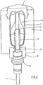
- the basic structure of a device for forming preforms (1) in container (2) is in Fig. 1 and in Fig. 2 shown.
- the device for forming the container (2) consists essentially of a blowing station (3), which is provided with a blow mold (4) into which a preform (1) can be inserted.
- the preform (1) may be a polyethylene terephthalate injection-molded part.
- the blow mold (4) consists of mold halves (5, 6) and a bottom part (7), which is a lifting device (8) is positionable.
- the preform (1) can be held in the region of the blowing station (3) by a transport mandrel (9) which, together with the preform (1), passes through a plurality of treatment stations within the device. But it is also possible to insert the preform (1) directly into the blow mold (4), for example via tongs or other handling means.
- a connecting piston (10) is arranged, which feeds the preform (1) compressed air and at the same time makes a seal relative to the transport mandrel (9).
- a connecting piston (10) is arranged, which feeds the preform (1) compressed air and at the same time makes a seal relative to the transport mandrel (9).
- a stretch rod (11) which is positioned by a cylinder (12).
- the use of curve segments is particularly useful when a plurality of blowing stations (3) are arranged on a rotating blowing wheel.
- a use of cylinders (12) is expedient if stationarily arranged blowing stations (3) are provided.
- the stretching system is designed such that a tandem arrangement of two cylinders (12) is provided. From a primary cylinder (13), the stretch rod (11) is first moved to the area of a bottom (14) of the preform (1) before the beginning of the actual stretching operation.
- the primary cylinder (13) with extended stretching rod together with a carriage (15) carrying the primary cylinder (13) is positioned by a secondary cylinder (16) or via a cam control.
- the secondary cylinder (16) in such a cam-controlled manner that a current stretching position is predetermined by a guide roller (17) which slides along a curved path during the execution of the stretching operation.
- the guide roller (17) is pressed by the secondary cylinder (16) against the guideway.
- the carriage (15) slides along two guide elements (18).
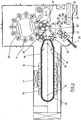
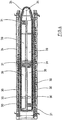
- Fig. 2 shows in addition to the blown container (2) and dashed lines drawn the preform (1) and schematically a developing container bladder (23).
- Fig. 3 shows the basic structure of a blow molding machine, which is provided with a heating section (24) and a rotating blowing wheel (25).
- a preform input (26) the preforms (1) are transported by transfer wheels (27, 28, 29) into the region of the heating path (24).
- heating radiator (30) and blower (31) are arranged to temper the preforms (1).
- blowing wheel (25) After a sufficient temperature control of the preforms (1), they are transferred to the blowing wheel (25), in the region of which the blowing stations (3) are arranged.
- the finished blown containers (2) are fed by further transfer wheels to a delivery line (32).
- thermoplastic material different plastics can be used.
- PET, PEN or PP can be used.
- the expansion of the preform (1) during the orientation process is carried out by compressed air supply.
- the compressed air supply is in a Vorblasphase in which gas, for example, compressed air, is supplied at a low pressure level and divided into a subsequent Hauptblasphase in which gas is supplied at a higher pressure level.
- gas for example, compressed air
- the heating section (24) is formed of a plurality of revolving transport elements (33) which are strung together like a chain and guided by guide wheels (34).
- guide wheels (34) In particular, it is envisaged to open a substantially rectangular basic contour by the chain-like arrangement.
- the heating section (24) in the region of the transfer wheel (29) and an input wheel (35) facing extension of the heating section (24) a single relatively large-sized guide wheel (34) and in the region of adjacent deflections two comparatively smaller dimensioned guide wheels (36) used , In principle, however, any other guides are conceivable.
- the arrangement shown to be particularly useful since in the region of the corresponding extent of the heating section (24) three deflecting wheels (34, 36) are positioned, and although in each case the smaller deflection wheels (36) in the region of the transition to the linear curves of the heating section (24) and the larger deflection wheel (34) in the immediate transfer area to the transfer wheel (29) and the input wheel (35).
- chain-like transport elements (33) it is for example also possible to use a rotating heating wheel.
- modified heating section (24) can be tempered by the larger number of radiant heaters (30) a larger amount of preforms (1) per unit time.
- the fans (31) introduce cooling air into the region of cooling air ducts (39), which in each case oppose the associated radiant heaters (30) and emit the cooling air via outflow openings.
- the arrangement of the outflow directions, a flow direction for the cooling air is realized substantially transversely to a transport direction of the preforms (1).
- the cooling air ducts (39) can provide reflectors for the heating radiation in the area opposite the radiant heaters (30), and it is likewise possible to realize cooling of the radiant heaters (30) via the discharged cooling air.
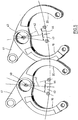
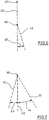
- Fig. 5 illustrates the arrangement of mold carriers (19, 20) with each other in an open state of the blowing station (3) partially overlapping mold carriers (19, 20).
- the mold carriers (19, 20) ribs, which are arranged at a different height level.
- the mold carriers (19, 20) are arranged pivotable relative to the axis of rotation (40) of the blowing station (3). The pivoting can be controlled by a steering lever (41).
- the mold supports (19) Relative to a parting plane (42) of the blowing station (3), the mold supports (19) have opening angles (43, 44). In one illustrated embodiment, the opening angles (43, 44) are different relative to one another.
- Fig. 6 shows a schematic representation of a further embodiment.
- the parting plane (42) is inclined with respect to a radially extending reference plane (45) of the blowing wheel (25) with an inclination angle (46).
- the reference plane (45) extends through an axis of rotation (47) of the blowing wheel (25) and through the axis of rotation (40) of the mold carriers (19, 20) of the blowing station (3).
- a corresponding oblique arrangement of the parting plane (42) also supports reduced opening angles (43, 44) of the blowing stations (3).
- the relative to the reference plane (45) inclined arrangement of the parting plane (42) can be implemented statically or only for certain periods of time dynamically. A dynamic realization can be achieved, for example, by a pivotable arrangement of the blowing stations (3).
- Fig. 7 illustrates again the realization relative to each other different opening angle (43, 44).
- the different opening angles (43) can be realized, for example, by a movement of the mold carriers (19, 20) which is in the same direction but at different speeds with respect to the parting plane (42).
- the mold carriers (19, 20) are rigidly coupled with respect to their motion control.
Landscapes
- Engineering & Computer Science (AREA)
- Manufacturing & Machinery (AREA)
- Mechanical Engineering (AREA)
- Blow-Moulding Or Thermoforming Of Plastics Or The Like (AREA)
- Moulds For Moulding Plastics Or The Like (AREA)
Abstract
Description
Die Erfindung betrifft eine Vorrichtung zur Blasformung von Behältern, die mindestens zwei auf einem Blasrad angeordnete Blasstationen zur Umformung von thermoplastischen Vorformlingen in die Behälter aufweist und bei der jede der Blasstationen mit mindestens zwei von Formträgern gehalterten Blasformsegmenten versehen ist sowie bei der die Blasformsegmente in einem geschlossenen Zustand der Blasstation entlang einer Trennebene angeordnet und von mindestens einem Verriegelungselement relativ zueinander fixiert sind.The invention relates to a device for blow-molding containers, which has at least two blowing stations arranged on a blowing wheel for forming thermoplastic preforms into the containers and in which each of the blowing stations is provided with at least two blow mold segments held by mold carriers, and in which the blow mold segments are in a closed one Condition of the blowing station are arranged along a parting plane and fixed by at least one locking element relative to each other.
Bei einer derartigen Behälterformung durch Blasdruckeinwirkung werden Vorformlinge aus einem thermoplastischen Material, beispielsweise Vorformlinge aus PET (Polyethylenterephtalat), innerhalb einer Blasmaschine unterschiedlichen Bearbeitungsstationen zugeführt. Typischerweise weist eine derartige Blasmaschine eine Heizeinrichtung sowie eine Blaseinrichtung auf, in deren Bereich der zuvor temperierte Vorformling durch biaxiale Orientierung zu einem Behälter expandiert wird. Die Expansion erfolgt mit Hilfe von Druckluft, die in den zu expandierenden Vorformling eingeleitet wird. Der verfahrenstechnische Ablauf bei einer derartigen Expansion des Vorformlings wird in der
Der grundsätzliche Aufbau einer Blasstation zur Behälterformung wird in der
Innerhalb der Vorrichtung zur Blasformung können die Vorformlinge sowie die geblasenen Behälter mit Hilfe unterschiedlicher Handhabungseinrichtungen transportiert werden. Bewährt hat sich insbesondere die Verwendung von Transportdornen, auf die die Vorformlinge aufgesteckt werden. Die Vorformlinge können aber auch mit anderen Trageinrichtungen gehandhabt werden. Die Verwendung von Greifzangen zur Handhabung von Vorformlingen und die Verwendung von Spreizdornen, die zur Halterung in einen Mündungsbereich des Vorformlings einführbar sind, gehören ebenfalls zu den verfügbaren Konstruktionen.Within the blow molding apparatus, the preforms as well as the blown containers can be transported by means of different handling devices. In particular, the use of transport mandrels, onto which the preforms are plugged, has proven to be useful. The preforms can also be handled with other support devices. The use of gripper tongs for handling preforms and the use of expansion mandrels which are insertable into a muzzle region of the preform for mounting are also among the available constructions.
Die bereits erläuterte Handhabung der Vorformlinge erfolgt zum einen bei den sogenannten Zweistufenverfahren, bei denen die Vorformlinge zunächst in einem Spritzgußverfahren hergestellt, anschließend zwischengelagert und erst später hinsichtlich ihrer Temperatur konditioniert und zu einem Behälter aufgeblasen werden. Zum anderen erfolgt eine Anwendung bei den sogenannten Einstufenverfahren, bei denen die Vorformlinge unmittelbar nach ihrer spritzgußtechnischen Herstellung und einer ausreichenden Verfestigung geeignet temperiert und anschließend aufgeblasen werden.The already described handling of the preforms takes place firstly in the so-called two-stage process, in which the preforms are first produced in an injection molding process, then temporarily stored and later conditioned in terms of their temperature and inflated to a container. On the other hand, there is an application in the so-called one-step process, in which the preforms are suitably tempered and then inflated immediately after their injection molding production and adequate solidification.
Im Hinblick auf die verwendeten Blasstationen sind unterschiedliche Ausführungsformen bekannt. Bei Blasstationen, die auf rotierenden Transporträdern angeordnet sind, ist eine buchartige Aufklappbarkeit der Formträger häufig anzutreffen. Es ist aber auch möglich, relativ zueinander verschiebliche oder andersartig geführte Form-träger einzusetzen. Bei ortsfesten Blasstationen, die insbesondere dafür geeignet sind, mehrere Kavitäten zur Behälterformung aufzunehmen, werden typischerweise parallel zueinander angeordnete Platten als Formträger verwendet.With regard to the blow molding stations used, different embodiments are known. In blow stations, which are arranged on rotating transport wheels, a book-like unfoldability of the mold carrier is frequently encountered. But it is also possible to use relatively displaceable or differently guided mold carrier. In fixed blowing stations, which are particularly suitable for receiving a plurality of cavities for container molding, typically plates arranged parallel to one another are used as mold carriers.
Aus der
In der
Ständig zunehmende Anforderungen an die Leistungsfähigkeit der Blasmaschinen führen dazu, daß Blasräder mit einer relativ großen Anzahl von Blasstationen verwendet werden und daß die Blasräder relativ schnell rotieren. Die große Anzahl der Blasstationen führt zu einem großen Durchmesser der Blasräder und die hohen Drehzahlen führen zu starken Brems- und Beschleunigungskräften aufgrund der kinetischen Energie der bewegten Massen.Constantly increasing demands on the performance of the blow molding machines mean that blowing wheels with a relatively large number of blowing stations are used and that the blowing wheels rotate relatively quickly. The large number of blowing stations leads to a large diameter of the blowing wheels and the high speeds lead to strong braking and acceleration forces due to the kinetic energy of the moving masses.
Zur Verringerung dieser nachteiligen Effekte ist bereits vorgeschlagen worden, die Blasräder mit einer kompakten Anordnung von Blasstationen zu konstruieren. Eine Vielzahl von Konstruktionsvarianten sind in der
Das Dokument
Aufgabe der vorliegenden Erfindung ist es, eine Vorrichtung der einleitend genannten Art derart zu konstruieren, dass eine besonders kompakte Konstruktion der Blasmaschine erreicht wird.Object of the present invention is to construct a device of the aforementioned type such that a particularly compact construction of the blow molding machine is achieved.
Dabei wird erfindungsgemäss zur Realisierung einer Konturverschachtelung vorgeschlagen, dass sich die benachbarten Formträger im Bereich von Verrippungen überlappen, die auf relativ zueinander unterschiedlichen Höhenniveaus angeordnet sind.In this case, according to the invention, in order to realize a contour interleaving, it is proposed that the adjacent mold carriers overlap in the region of ribs which are arranged at relatively different height levels.
Die bekannten Blasstationen sind derart konstruiert, dass zur Mittelebene symmetrisch angeordnete Formträger oder Tragarme verwendet werden, die symmetrisch und gleichsinnig angesteuert werden. Dies führt zu einem Abstand zwischen den Blasstationen, der ein vollständiges Öffnen der Blasstationen zu jeder beliebigen Rotationspositionierung des Blasrades ermöglicht.The known blow molding stations are constructed in such a way that symmetrically arranged mold carriers or support arms are used which are driven symmetrically and in the same direction to the center plane. This results in a spacing between the blowing stations which allows for complete opening of the blowing stations to any rotational positioning of the blowing wheel.
Bei der erfindungsgemäss vorgeschlagenen Anordnung der Formträger wird berücksichtigt, dass zum einen die in die Blasstation einzusetzenden Vorformling einen erheblich kleineren Durchmesser als die auszugebenden Flaschen aufweisen. Darüber hinaus wird berücksichtigt, dass sowohl die Blasstationen als auch die Übergabeelemente zur Halterung der Vorformlinge bzw. der Flaschen während der Durchführung der Übergabevorgänge Bewegungen durchführen. Schliesslich wird ebenfalls berücksichtigt, dass ein Übergabevorgang nicht exakt in einer radialen Richtung des Blasrades erfolgt, sondern dass zumindest überlagert weitere Bewegungskomponenten auftreten.In the arrangement of the mold carriers proposed according to the invention, it is taken into account that, on the one hand, the preform to be inserted into the blowing station has a considerably smaller diameter than the bottles to be dispensed. In addition, it is considered that both the blow molding stations and the transfer elements for holding the preforms or the bottles perform movements during the execution of the transfer processes. Finally, it is also considered that a transfer process does not take place exactly in a radial direction of the blowing wheel, but that at least superimposed further movement components occur.
Durch die vorgeschlagene erfindungsgemässe Anordnung der Formträger erfolgt eine jeweilige Positionierung der Formträger jeweils derart, dass der beabsichtigte Eingabe- oder Ausgabevorgang kollisionsfrei möglich ist. Eine unnötig weite Öffnung der Blasstationen bzw. ungünstige Öffnungswinkel der Formträger werden hingegen vermieden.The proposed inventive arrangement of the mold carrier is a respective positioning of the mold carrier in each case such that the intended input or output process is possible without collision. An unnecessarily wide opening of the blowing stations or unfavorable opening angle of the mold carrier, however, be avoided.
Bei einer Anordnung der Blasstationen auf einem rotierenden Blasrad können somit auf einer vorgegebenen Blasradgrösse erheblich mehr Blasstationen angeordnet werden bzw. eine vorgegebene Anzahl von Blasstationen kann auf einem deutlich verkleinerten Blasrad positioniert werden. Hieraus ergeben sich erhebliche kinematische Vorteile im Hinblick auf die auftretenden Drehmomente bzw. Trägheitsmomente.With an arrangement of the blowing stations on a rotating blowing wheel considerably more blowing stations can thus be arranged on a given Blasradgrösse or a predetermined number of blow molding stations can be positioned on a much smaller blower. This results in considerable kinematic advantages with regard to the occurring torques or moments of inertia.
Eine Anordnung der Blasstationen mit geringem Abstand relativ zueinander wird dadurch unterstützt, dass einander benachbarte Formträger sich in mindestens einer Öffnungspositionierung mindestens bereichsweise überdecken.An arrangement of the blowing stations with a small distance relative to each other is supported by the fact that adjacent mold carriers at least partially overlap in at least one opening position.
Eine Anpassung an die Kinematik von Übergabevorgängen kann dadurch erfolgen, daß die Formträger relativ zu einer Trennebene relativ zueinander unterschiedliche Öffnungswinkel aufweisen.An adaptation to the kinematics of transfer operations can take place in that the mold carrier relative to a parting plane relative to each other have different opening angle.
Eine einfache mechanische Ansteuerbarkeit wird dadurch bereitgestellt, daß die Formträger relativ zur Trennebene gekoppelt und gegensinnig positionierbar sind.A simple mechanical controllability is provided by the fact that the mold carriers are coupled relative to the parting plane and can be positioned in opposite directions.
Eine weitere Optimierung der Bewegungen der Formträger kann dadurch erfolgen, daß die Formträger relativ zur Trennebene relativ zueinander unabhängig positionierbar angeordnet sind.
Eine weitere Anpassung an die Bewegungsrichtungen bei der Durchführung von Übergabevorgängen kann dadurch erfolgen, daß die Trennebene mit einem Neigungswinkel relativ zu einer radial verlaufenden Bezugsebene angeordnet ist.A further optimization of the movements of the mold carrier can be effected in that the mold carriers are arranged relative to the separation plane relative to each other independently positionable.
A further adaptation to the directions of movement in the implementation of transfer operations can be effected in that the parting plane is arranged with an inclination angle relative to a radially extending reference plane.
Eine einfache konstruktive Realisierung wird dadurch unterstützt, daß die Trennebene relativ zur Bezugsebene mit einem konstanten Neigungswinkel angeordnet ist.A simple structural realization is supported by the fact that the parting plane is arranged relative to the reference plane with a constant inclination angle.
Eine weitere Möglichkeit zur Reduzierung des Abstandes der Blasstation wird dadurch bereitgestellt, daß der Neigungswinkel zeitlich veränderlich ist.Another way to reduce the distance of the blowing station is provided by the fact that the angle of inclination is temporally variable.
Zur Optimierung der Übergabevorgänge ist ebenfalls daran gedacht, daß die Blasstation verschwenkbar angeordnet ist.To optimize the transfer processes is also thought that the blowing station is pivotally mounted.
In den Zeichnungen sind Ausführungsbeispiele der Erfindung schematisch dargestellt. Es zeigen:
- Fig. 1
- Eine perspektivische Darstellung einer Blasstation zur Herstellung von Behältern aus Vorformlingen,
- Fig. 2
- einen Längsschnitt durch eine Blasform, in der ein Vorformling gereckt und expandiert wird,
- Fig. 3
- eine Skizze zur Veranschaulichung eines grundsätzlichen Aufbaus einer Vorrichtung zur Blasformung von Behältern,
- Fig. 4
- eine modifizierte Heizstrecke mit vergrößerter Heizkapazität,
- Fig. 5
- eine schematische Darstellung der Tragarme von zwei nebeneinander angeordneten Blasstationen mit teilweiser Überdeckung benachbarter Tragarme,
- Fig. 6
- eine schematische Darstellung einer schräg zu einer radialen Richtung des Blasrades angeordneten Trennebene einer Blasstation und
- Fig. 7
- eine schematische Darstellung, die eine bezüglich einer Trennebene der Blasstation unsymmetrische Öffnung der Tragarme veranschaulicht.
- Fig. 1
- A perspective view of a blowing station for the production of containers from preforms,
- Fig. 2
- a longitudinal section through a blow mold, in which a preform is stretched and expanded,
- Fig. 3
- a sketch to illustrate a basic structure of a device for blow molding containers,
- Fig. 4
- a modified heating section with increased heating capacity,
- Fig. 5
- a schematic representation of the support arms of two juxtaposed blowing stations with partial coverage of adjacent support arms,
- Fig. 6
- a schematic representation of an obliquely arranged to a radial direction of the blowing wheel parting plane of a blowing station and
- Fig. 7
- a schematic representation illustrating a respect to a separation plane of the blowing station unbalanced opening of the support arms.
Der prinzipielle Aufbau einer Vorrichtung zur Umformung von Vorformlingen (1) in Behälter (2) ist in
Die Vorrichtung zur Formung des Behälters (2) besteht im wesentlichen aus einer Blasstation (3), die mit einer Blasform (4) versehen ist, in die ein Vorformling (1) einsetzbar ist. Der Vorformling (1) kann ein spritz-gegossenes Teil aus Polyethylenterephthalat sein. Zur Ermöglichung eines Einsetzens des Vorformlings (1) in die Blasform (4) und zur Ermöglichung eines Herausnehmens des fertigen Behälters (2) besteht die Blasform (4) aus Formhälften (5, 6) und einem Bodenteil (7), das von einer Hubvorrichtung (8) positionierbar ist. Der Vorformling (1) kann im Bereich der Blasstation (3) von einem Transportdorn (9) gehalten sein, der gemeinsam mit dem Vorformling (1) eine Mehrzahl von Behandlungsstationen innerhalb der Vorrichtung durchläuft. Es ist aber auch möglich, den Vorformling (1) beispielsweise über Zangen oder andere Handhabungsmittel direkt in die Blasform (4) einzusetzen.The device for forming the container (2) consists essentially of a blowing station (3), which is provided with a blow mold (4) into which a preform (1) can be inserted. The preform (1) may be a polyethylene terephthalate injection-molded part. To allow the preform (1) to be inserted into the blow mold (4) and to allow the finished container (2) to be removed, the blow mold (4) consists of mold halves (5, 6) and a bottom part (7), which is a lifting device (8) is positionable. The preform (1) can be held in the region of the blowing station (3) by a transport mandrel (9) which, together with the preform (1), passes through a plurality of treatment stations within the device. But it is also possible to insert the preform (1) directly into the blow mold (4), for example via tongs or other handling means.
Zur Ermöglichung einer Druckluftzuleitung ist unterhalb des Transportdornes (9) ein Anschlußkolben (10) angeordnet, der dem Vorformling (1) Druckluft zuführt und gleichzeitig eine Abdichtung relativ zum Transportdorn (9) vornimmt. Bei einer abgewandelten Konstruktion ist es grundsätzlich aber auch denkbar, feste Druckluftzuleitungen zu verwenden.To allow a compressed air supply line below the transport mandrel (9) a connecting piston (10) is arranged, which feeds the preform (1) compressed air and at the same time makes a seal relative to the transport mandrel (9). In a modified construction, it is basically also conceivable to use solid compressed air supply lines.
Eine Reckung des Vorformlings (1) erfolgt mit Hilfe einer Reckstange (11), die von einem Zylinder (12) positioniert wird. Grundsätzlich ist es aber auch denkbar, eine mechanische Positionierung der Reckstange (11) über Kurvensegmente durchzuführen, die von Abgriffrollen beaufschlagt sind. Die Verwendung von Kurvensegmenten ist insbesondere dann zweckmäßig, wenn eine Mehrzahl von Blasstationen (3) auf einem rotierenden Blasrad angeordnet sind. Eine Verwendung von Zylindern (12) ist zweckmäßig, wenn ortsfest angeordnete Blasstationen (3) vorgesehen sind.A stretching of the preform (1) by means of a stretch rod (11) which is positioned by a cylinder (12). In principle, however, it is also conceivable to perform a mechanical positioning of the stretch rod (11) via curve segments, which are acted upon by Abgriffrollen. The use of curve segments is particularly useful when a plurality of blowing stations (3) are arranged on a rotating blowing wheel. A use of cylinders (12) is expedient if stationarily arranged blowing stations (3) are provided.
Bei der in
Nach einem Schließen der im Bereich von Formträgern (19, 20) angeordneten Formhälften (5, 6) erfolgt eine Verriegelung der Formträger (19, 20) relativ zueinander mit Hilfe einer Verriegelungseinrichtung (40).After closing the mold halves (5, 6) arranged in the region of mold carriers (19, 20), the mold carriers (19, 20) are locked relative to one another with the aid of a locking device (40).
Zur Anpassung an unterschiedliche Formen eines Mündungsabschnittes (21) des Vorformlings (1) ist gemäß
Um einen Vorformling (1) derart in einen Behälter (2) umformen zu können, daß der Behälter (2) Materialeigenschaften aufweist, die eine lange Verwendungsfähigkeit von innerhalb des Behälters (2) abgefüllten Lebensmitteln, insbesondere von Getränken, gewährleisten, müssen spezielle verfahrensschritte bei der Beheizung und Orientierung der Vorformlinge (1) eingehalten werden. Darüber hinaus können vorteilhafte Wirkungen durch Einhaltung spezieller Dimensionierungsvorschriften erzielt werden.In order to be able to transform a preform (1) into a container (2) in such a way that the container (2) has material properties which ensure a long usefulness of foodstuffs filled inside the container (2), in particular beverages, special process steps must be taken the heating and orientation of the preforms (1) are maintained. In addition, advantageous effects can be achieved by adhering to special dimensioning regulations.
Als thermoplastisches Material können unterschiedliche Kunststoffe verwendet werden. Einsatzfähig sind beispielsweise PET, PEN oder PP.As a thermoplastic material different plastics can be used. For example, PET, PEN or PP can be used.
Die Expansion des Vorformlings (1) während des Orientierungsvorganges erfolgt durch Druckluftzuführung. Die Druckluftzuführung ist in eine Vorblasphase, in der Gas, zum Beispiel Preßluft, mit einem niedrigen Druckniveau zugeführt wird und in eine sich anschließende Hauptblasphase unterteilt, in der Gas mit einem höheren Druckniveau zugeführt wird. Während der vorblasphase wird typischerweise Druckluft mit einem Druck im Intervall von 10 bar bis 25 bar verwendet und während der Hauptblasphase wird Druckluft mit einem Druck im Intervall von 25 bar bis 40 bar zugeführt.The expansion of the preform (1) during the orientation process is carried out by compressed air supply. The compressed air supply is in a Vorblasphase in which gas, for example, compressed air, is supplied at a low pressure level and divided into a subsequent Hauptblasphase in which gas is supplied at a higher pressure level. During the pre-blowing phase, compressed air with a pressure in the interval of 10 bar to 25 bar is typically used and during the main blowing phase compressed air is supplied at a pressure in the interval of 25 bar to 40 bar.
Aus
Zur Ermöglichung einer möglichst dichten Anordnung des Übergaberades (29) und des Eingaberades (35) relativ zueinander erweist sich die dargestellte Anordnung als besonders zweckmäßig, da im Bereich der entsprechenden Ausdehnung der Heizstrecke (24) drei Umlenkräder (34, 36) positioniert sind, und zwar jeweils die kleineren Umlenkräder (36) im Bereich der Überleitung zu den linearen Verläufen der Heizstrecke (24) und das größere Umlenkrad (34) im unmittelbaren Übergabebereich zum Übergaberad (29) und zum Eingaberad (35). Alternativ zur Verwendung von ketten-artigen Transportelementen (33) ist es beispielsweise auch möglich, ein rotierendes Heizrad zu verwenden.To enable a possible dense arrangement of the transfer wheel (29) and the input wheel (35) relative to each other, the arrangement shown to be particularly useful, since in the region of the corresponding extent of the heating section (24) three deflecting wheels (34, 36) are positioned, and Although in each case the smaller deflection wheels (36) in the region of the transition to the linear curves of the heating section (24) and the larger deflection wheel (34) in the immediate transfer area to the transfer wheel (29) and the input wheel (35). As an alternative to the use of chain-like transport elements (33), it is for example also possible to use a rotating heating wheel.
Nach einem fertigen Blasen der Behälter (2) werden diese von einem Entnahmerad (37) aus dem Bereich der Blasstationen (3) herausgeführt und über das Übergaberad (28) und ein Ausgaberad (38) zur Ausgabestrecke (32) transportiert.After a finished blowing of the containers (2) they are led out of the region of the blow stations (3) by a removal wheel (37) and transported via the transfer wheel (28) and a delivery wheel (38) to the delivery line (32).
In der in
Relativ zu einer Trennebene (42) der Blasstation (3) weisen die Formträger (19) Öffnungswinkel (43, 44) auf. Bei einem dargestellten Ausführungsbeispiel sind die Öffnungswinkel (43, 44) relativ zueinander unterschiedlich.Relative to a parting plane (42) of the blowing station (3), the mold supports (19) have opening angles (43, 44). In one illustrated embodiment, the opening angles (43, 44) are different relative to one another.
Die vorstehend beschriebenen Ausführungsvarianten können sowohl alternativ als auch gemeinsam realisiert werden. Ein Optimum einer Kompaktheit wird bei einer gemeinsamen Realisierung aller Ausführungsvarianten erreicht.The embodiments described above can be realized both alternatively and jointly. An optimum of compactness is achieved in a common realization of all variants.
Claims (9)
- A device for blow moulding containers (2), which has at least two blowing stations (3) arranged on a blow wheel (25) for shaping thermoplastic preforms (1) into the container (2), and in the case of which each of the blowing stations (3) is provided with at least two blow moulding segments held by mould carriers (19, 20), and in the case of which the blow moulding segments are arranged along a separating plane (42) in a closed state of the blowing station (3) and are fixed relative to one another by at least one locking element, wherein, in at least one operating state, at least one mould carrier (19, 20) of at least one blowing station (3) extends in an area, which is in line with a reference area, which is defined by a volume of an identical mould carrier (19, 20) of an adjacent blowing station (3) mirrored on a radial centre plane (45), which is arranged in a maximum open positioning (43, 44) upon the mirroring, characterised in thatthe centre plane (45) runs through an axis of rotation (47) of the blow wheel (25) and an axis of rotation (40) of the mould carriers (19, 20), wherein the adjacent mould carriers (19, 20) overlap in the area of ribbings, which are arranged at height levels, which differ relative to one another.
- The device according to claim 1, characterised in that adjacent mould carriers (19, 20) overlap at least area by area in at least one open positioning.
- The device according to any one of claims 1 or 2, characterised in that, relative to a separating plane (20), the mould carriers (19, 20) have opening angles (43, 44), which differ relative to one another.
- The device according to any one of claims 1 to 3, characterised in that the mould carriers (19, 20) are coupled relative to the separating plane (42) and can be positioned in the opposite direction.
- The device according to any one of claims 1 to 3, characterised in that, relative to the separating plane (42), the mould carriers (19, 20) are arranged so as to be capable of being positioned independently relative to one another.
- The device according to any one of claims 1 to 5, characterised in that the separating plane (42) is arranged at an angle of inclination (46) relative to a reference plane (45), which runs radially.
- The device according to claim 6, characterised in that the separating plane (42) is arranged at a constant angle of inclination (46) relative to the reference plane (45).
- The device according to claim 6, characterised in that the angle of inclination (46) can be changed temporally.
- The device according to any one of claims 1 to 8, characterised in that the blowing station (3) is arranged so as to be capable of being pivoted.
Priority Applications (1)
| Application Number | Priority Date | Filing Date | Title |
|---|---|---|---|
| PL04022882T PL1520681T3 (en) | 2003-10-04 | 2004-09-24 | Device for blowmoulding plastic containers/bottles |
Applications Claiming Priority (2)
| Application Number | Priority Date | Filing Date | Title |
|---|---|---|---|
| DE10346089 | 2003-10-04 | ||
| DE10346089A DE10346089A1 (en) | 2003-10-04 | 2003-10-04 | Device for blow molding containers |
Publications (3)
| Publication Number | Publication Date |
|---|---|
| EP1520681A1 EP1520681A1 (en) | 2005-04-06 |
| EP1520681B1 EP1520681B1 (en) | 2006-05-17 |
| EP1520681B2 true EP1520681B2 (en) | 2016-12-21 |
Family
ID=34306251
Family Applications (1)
| Application Number | Title | Priority Date | Filing Date |
|---|---|---|---|
| EP04022882.7A Expired - Lifetime EP1520681B2 (en) | 2003-10-04 | 2004-09-24 | Device for blowmoulding plastic containers/bottles |
Country Status (6)
| Country | Link |
|---|---|
| EP (1) | EP1520681B2 (en) |
| CN (1) | CN100493886C (en) |
| AT (1) | ATE326331T1 (en) |
| DE (2) | DE10346089A1 (en) |
| ES (1) | ES2264785T3 (en) |
| PL (1) | PL1520681T3 (en) |
Cited By (1)
| Publication number | Priority date | Publication date | Assignee | Title |
|---|---|---|---|---|
| US12170849B2 (en) | 2022-02-04 | 2024-12-17 | Applied Materials, Inc. | Pulsed illumination for fluid inspection |
Families Citing this family (9)
| Publication number | Priority date | Publication date | Assignee | Title |
|---|---|---|---|---|
| FR2878184B1 (en) * | 2004-11-19 | 2007-03-02 | Sidel Sas | MOLDING DEVICE FOR MANUFACTURING CONTAINERS OF THERMOPLASTIC MATERIAL |
| FR2881678B1 (en) * | 2005-02-08 | 2009-04-24 | Sidel Sas | METHOD FOR OPENING AND CLOSING CONTROL OF A BLOW MOLD AND AGENCY BLOWING DEVICE FOR ITS IMPLEMENTATION |
| DE102005034541A1 (en) * | 2005-07-23 | 2007-02-01 | Sig Technology Ltd. | Method and apparatus for blow molding containers |
| DE102007022638A1 (en) * | 2007-05-15 | 2008-11-20 | Sig Technology Ag | Device for blow molding containers |
| DE102008029531A1 (en) * | 2008-06-21 | 2009-12-24 | Krones Ag | Method and device for inserting a preform into and for removing a bottle from a blow molding machine |
| DE102009049260A1 (en) | 2009-10-13 | 2011-04-21 | Krones Ag | Mold carrier with drive device |
| FR2969955B1 (en) * | 2011-01-04 | 2013-02-01 | Serac Group | DEVICE FOR BLOWING CONTAINERS |
| CN102765185B (en) * | 2012-07-28 | 2015-09-09 | 台州迈格机械模具有限公司 | Folder embryo manipulator |
| CN103171126B (en) * | 2013-03-19 | 2015-07-01 | 江苏新美星包装机械股份有限公司 | Bottle blowing machine |
Citations (1)
| Publication number | Priority date | Publication date | Assignee | Title |
|---|---|---|---|---|
| US4035463A (en) † | 1968-01-16 | 1977-07-12 | Heidenreich & Harbeck | Method of making hollow articles, especially bottles, of thermoplastics |
Family Cites Families (3)
| Publication number | Priority date | Publication date | Assignee | Title |
|---|---|---|---|---|
| FR2793722B1 (en) * | 1999-05-17 | 2001-08-03 | Sidel Sa | BLOWING MACHINE COMPRISING A CLOSING AND LOCKING MECHANISM COMBINED WITH A MOLDING UNIT |
| DE19948474B4 (en) * | 1999-10-08 | 2012-05-24 | Khs Corpoplast Gmbh | Method and apparatus for blow molding containers |
| IT1313996B1 (en) * | 1999-11-18 | 2002-12-03 | Smi Spa | ROTARY MACHINE FOR THE PRODUCTION OF CONTAINERS OR DIPLASTIC BOTTLES FOR BLOWING STARTING FROM A PRINTED PREFORM AND MOLD |
-
2003
- 2003-10-04 DE DE10346089A patent/DE10346089A1/en not_active Withdrawn
-
2004
- 2004-09-24 PL PL04022882T patent/PL1520681T3/en unknown
- 2004-09-24 AT AT04022882T patent/ATE326331T1/en active
- 2004-09-24 ES ES04022882T patent/ES2264785T3/en not_active Expired - Lifetime
- 2004-09-24 EP EP04022882.7A patent/EP1520681B2/en not_active Expired - Lifetime
- 2004-09-24 DE DE502004000575T patent/DE502004000575D1/en not_active Expired - Lifetime
- 2004-09-30 CN CNB2004100757408A patent/CN100493886C/en not_active Expired - Lifetime
Patent Citations (1)
| Publication number | Priority date | Publication date | Assignee | Title |
|---|---|---|---|---|
| US4035463A (en) † | 1968-01-16 | 1977-07-12 | Heidenreich & Harbeck | Method of making hollow articles, especially bottles, of thermoplastics |
Cited By (1)
| Publication number | Priority date | Publication date | Assignee | Title |
|---|---|---|---|---|
| US12170849B2 (en) | 2022-02-04 | 2024-12-17 | Applied Materials, Inc. | Pulsed illumination for fluid inspection |
Also Published As
| Publication number | Publication date |
|---|---|
| ES2264785T3 (en) | 2007-01-16 |
| CN100493886C (en) | 2009-06-03 |
| EP1520681A1 (en) | 2005-04-06 |
| EP1520681B1 (en) | 2006-05-17 |
| DE502004000575D1 (en) | 2006-06-22 |
| PL1520681T3 (en) | 2006-11-30 |
| DE10346089A1 (en) | 2005-05-12 |
| CN1651221A (en) | 2005-08-10 |
| ATE326331T1 (en) | 2006-06-15 |
Similar Documents
| Publication | Publication Date | Title |
|---|---|---|
| EP2139665B1 (en) | Method and device for blow-moulding containers | |
| EP2144742B1 (en) | Device for blow molding containers | |
| EP2429795B1 (en) | Method and apparatus for blow molding and for filling containers | |
| EP1789247B1 (en) | Device for blow molding containers | |
| EP1871590B1 (en) | Method and device for blow-moulding containers | |
| EP1907190B1 (en) | Method and device for blow-moulding containers | |
| EP1535719B1 (en) | Device for blow-molding containers | |
| EP1520681B2 (en) | Device for blowmoulding plastic containers/bottles | |
| EP1350612B1 (en) | Apparatus for handling of preforms with separatly controlable arms mounted radially on a turning disk | |
| EP1226017B1 (en) | Method and device for blow moulding containers | |
| EP2694270B1 (en) | Device for blow-moulding containers | |
| EP1773571B1 (en) | Method and device for blow moulding containers | |
| EP1732743B1 (en) | Method and device for blow-forming containers using a reduced pressure increasing speed | |
| EP1297942B1 (en) | Apparatus for handling strech-blow-moulded containers using a conveying wheel, whereby a gripping element is relatively rotatable to a carrier arm and controlled by a cam | |
| EP1566258B1 (en) | Apparatus for machining workpieces | |
| EP1535720B1 (en) | Apparatus for blow moulding articles | |
| EP1473139B1 (en) | Method and apparatus for blow moulding containers | |
| WO2007033631A2 (en) | Method and device for blow moulding containers using a controlled drawing bar | |
| EP2129508B1 (en) | Method for blow moulding containers | |
| DE102005008685A1 (en) | Blow moulding containers, e.g. polyester bottles, involves transporting preforms on the heating section to within a short distance of the blow-moulding wheel and then transferring them directly to the wheel | |
| WO2012116684A1 (en) | Method and apparatus for handling preforms | |
| EP2768654B1 (en) | Device for holding workpieces | |
| DE102024104932A1 (en) | Method and device for producing containers from preforms made of a thermoplastic material with high production output | |
| DE102006004940A1 (en) | Heating of preforms for blow-molding thermoplastic containers involves simultaneous use of two ovens with both heating paths arranged to be equal | |
| WO2001039958A1 (en) | Method and device for blow molding containers |
Legal Events
| Date | Code | Title | Description |
|---|---|---|---|
| PUAI | Public reference made under article 153(3) epc to a published international application that has entered the european phase |
Free format text: ORIGINAL CODE: 0009012 |
|
| AK | Designated contracting states |
Kind code of ref document: A1 Designated state(s): AT BE BG CH CY CZ DE DK EE ES FI FR GB GR HU IE IT LI LU MC NL PL PT RO SE SI SK TR |
|
| AX | Request for extension of the european patent |
Extension state: AL HR LT LV MK |
|
| 17P | Request for examination filed |
Effective date: 20050408 |
|
| GRAP | Despatch of communication of intention to grant a patent |
Free format text: ORIGINAL CODE: EPIDOSNIGR1 |
|
| AKX | Designation fees paid |
Designated state(s): AT BE BG CH CY CZ DE DK EE ES FI FR GB GR HU IE IT LI LU MC NL PL PT RO SE SI SK TR |
|
| GRAS | Grant fee paid |
Free format text: ORIGINAL CODE: EPIDOSNIGR3 |
|
| GRAA | (expected) grant |
Free format text: ORIGINAL CODE: 0009210 |
|
| AK | Designated contracting states |
Kind code of ref document: B1 Designated state(s): AT BE BG CH CY CZ DE DK EE ES FI FR GB GR HU IE IT LI LU MC NL PL PT RO SE SI SK TR |
|
| PG25 | Lapsed in a contracting state [announced via postgrant information from national office to epo] |
Ref country code: IE Free format text: LAPSE BECAUSE OF FAILURE TO SUBMIT A TRANSLATION OF THE DESCRIPTION OR TO PAY THE FEE WITHIN THE PRESCRIBED TIME-LIMIT Effective date: 20060517 Ref country code: NL Free format text: LAPSE BECAUSE OF FAILURE TO SUBMIT A TRANSLATION OF THE DESCRIPTION OR TO PAY THE FEE WITHIN THE PRESCRIBED TIME-LIMIT Effective date: 20060517 Ref country code: RO Free format text: LAPSE BECAUSE OF FAILURE TO SUBMIT A TRANSLATION OF THE DESCRIPTION OR TO PAY THE FEE WITHIN THE PRESCRIBED TIME-LIMIT Effective date: 20060517 Ref country code: SI Free format text: LAPSE BECAUSE OF FAILURE TO SUBMIT A TRANSLATION OF THE DESCRIPTION OR TO PAY THE FEE WITHIN THE PRESCRIBED TIME-LIMIT Effective date: 20060517 Ref country code: FI Free format text: LAPSE BECAUSE OF FAILURE TO SUBMIT A TRANSLATION OF THE DESCRIPTION OR TO PAY THE FEE WITHIN THE PRESCRIBED TIME-LIMIT Effective date: 20060517 Ref country code: SK Free format text: LAPSE BECAUSE OF FAILURE TO SUBMIT A TRANSLATION OF THE DESCRIPTION OR TO PAY THE FEE WITHIN THE PRESCRIBED TIME-LIMIT Effective date: 20060517 Ref country code: CZ Free format text: LAPSE BECAUSE OF FAILURE TO SUBMIT A TRANSLATION OF THE DESCRIPTION OR TO PAY THE FEE WITHIN THE PRESCRIBED TIME-LIMIT Effective date: 20060517 |
|
| REG | Reference to a national code |
Ref country code: GB Ref legal event code: FG4D Free format text: NOT ENGLISH |
|
| REG | Reference to a national code |
Ref country code: CH Ref legal event code: EP |
|
| REG | Reference to a national code |
Ref country code: IE Ref legal event code: FG4D Free format text: LANGUAGE OF EP DOCUMENT: GERMAN |
|
| REF | Corresponds to: |
Ref document number: 502004000575 Country of ref document: DE Date of ref document: 20060622 Kind code of ref document: P |
|
| PG25 | Lapsed in a contracting state [announced via postgrant information from national office to epo] |
Ref country code: DK Free format text: LAPSE BECAUSE OF FAILURE TO SUBMIT A TRANSLATION OF THE DESCRIPTION OR TO PAY THE FEE WITHIN THE PRESCRIBED TIME-LIMIT Effective date: 20060817 Ref country code: SE Free format text: LAPSE BECAUSE OF FAILURE TO SUBMIT A TRANSLATION OF THE DESCRIPTION OR TO PAY THE FEE WITHIN THE PRESCRIBED TIME-LIMIT Effective date: 20060817 |
|
| GBT | Gb: translation of ep patent filed (gb section 77(6)(a)/1977) |
Effective date: 20060904 |
|
| PG25 | Lapsed in a contracting state [announced via postgrant information from national office to epo] |
Ref country code: BE Free format text: LAPSE BECAUSE OF NON-PAYMENT OF DUE FEES Effective date: 20060930 Ref country code: MC Free format text: LAPSE BECAUSE OF NON-PAYMENT OF DUE FEES Effective date: 20060930 |
|
| REG | Reference to a national code |
Ref country code: CH Ref legal event code: NV Representative=s name: PA ALDO ROEMPLER |
|
| PG25 | Lapsed in a contracting state [announced via postgrant information from national office to epo] |
Ref country code: PT Free format text: LAPSE BECAUSE OF FAILURE TO SUBMIT A TRANSLATION OF THE DESCRIPTION OR TO PAY THE FEE WITHIN THE PRESCRIBED TIME-LIMIT Effective date: 20061017 |
|
| NLV1 | Nl: lapsed or annulled due to failure to fulfill the requirements of art. 29p and 29m of the patents act | ||
| REG | Reference to a national code |
Ref country code: IE Ref legal event code: FD4D |
|
| REG | Reference to a national code |
Ref country code: ES Ref legal event code: FG2A Ref document number: 2264785 Country of ref document: ES Kind code of ref document: T3 |
|
| ET | Fr: translation filed | ||
| PLBI | Opposition filed |
Free format text: ORIGINAL CODE: 0009260 |
|
| PLAX | Notice of opposition and request to file observation + time limit sent |
Free format text: ORIGINAL CODE: EPIDOSNOBS2 |
|
| PLBB | Reply of patent proprietor to notice(s) of opposition received |
Free format text: ORIGINAL CODE: EPIDOSNOBS3 |
|
| 26 | Opposition filed |
Opponent name: KRONES AKTIENGESELLSCHAFT Effective date: 20070216 |
|
| BERE | Be: lapsed |
Owner name: SIG TECHNOLOGY LTD. Effective date: 20060930 |
|
| PG25 | Lapsed in a contracting state [announced via postgrant information from national office to epo] |
Ref country code: GR Free format text: LAPSE BECAUSE OF FAILURE TO SUBMIT A TRANSLATION OF THE DESCRIPTION OR TO PAY THE FEE WITHIN THE PRESCRIBED TIME-LIMIT Effective date: 20060818 |
|
| PG25 | Lapsed in a contracting state [announced via postgrant information from national office to epo] |
Ref country code: BG Free format text: LAPSE BECAUSE OF FAILURE TO SUBMIT A TRANSLATION OF THE DESCRIPTION OR TO PAY THE FEE WITHIN THE PRESCRIBED TIME-LIMIT Effective date: 20060817 Ref country code: EE Free format text: LAPSE BECAUSE OF FAILURE TO SUBMIT A TRANSLATION OF THE DESCRIPTION OR TO PAY THE FEE WITHIN THE PRESCRIBED TIME-LIMIT Effective date: 20060517 |
|
| PG25 | Lapsed in a contracting state [announced via postgrant information from national office to epo] |
Ref country code: HU Free format text: LAPSE BECAUSE OF FAILURE TO SUBMIT A TRANSLATION OF THE DESCRIPTION OR TO PAY THE FEE WITHIN THE PRESCRIBED TIME-LIMIT Effective date: 20061118 Ref country code: LU Free format text: LAPSE BECAUSE OF NON-PAYMENT OF DUE FEES Effective date: 20060924 Ref country code: TR Free format text: LAPSE BECAUSE OF FAILURE TO SUBMIT A TRANSLATION OF THE DESCRIPTION OR TO PAY THE FEE WITHIN THE PRESCRIBED TIME-LIMIT Effective date: 20060517 |
|
| REG | Reference to a national code |
Ref country code: CH Ref legal event code: PCAR Free format text: ALDO ROEMPLER PATENTANWALT;BRENDENWEG 11 POSTFACH 154;9424 RHEINECK (CH) |
|
| PGFP | Annual fee paid to national office [announced via postgrant information from national office to epo] |
Ref country code: ES Payment date: 20080714 Year of fee payment: 5 |
|
| PG25 | Lapsed in a contracting state [announced via postgrant information from national office to epo] |
Ref country code: CY Free format text: LAPSE BECAUSE OF FAILURE TO SUBMIT A TRANSLATION OF THE DESCRIPTION OR TO PAY THE FEE WITHIN THE PRESCRIBED TIME-LIMIT Effective date: 20060517 |
|
| PGFP | Annual fee paid to national office [announced via postgrant information from national office to epo] |
Ref country code: PL Payment date: 20080710 Year of fee payment: 5 |
|
| PGFP | Annual fee paid to national office [announced via postgrant information from national office to epo] |
Ref country code: GB Payment date: 20080910 Year of fee payment: 5 |
|
| PGFP | Annual fee paid to national office [announced via postgrant information from national office to epo] |
Ref country code: CH Payment date: 20081209 Year of fee payment: 5 |
|
| RAP2 | Party data changed (patent owner data changed or rights of a patent transferred) |
Owner name: KHS CORPOPLAST GMBH & CO. KG |
|
| REG | Reference to a national code |
Ref country code: FR Ref legal event code: TP |
|
| REG | Reference to a national code |
Ref country code: CH Ref legal event code: PL |
|
| GBPC | Gb: european patent ceased through non-payment of renewal fee |
Effective date: 20090924 |
|
| PG25 | Lapsed in a contracting state [announced via postgrant information from national office to epo] |
Ref country code: LI Free format text: LAPSE BECAUSE OF NON-PAYMENT OF DUE FEES Effective date: 20090930 Ref country code: CH Free format text: LAPSE BECAUSE OF NON-PAYMENT OF DUE FEES Effective date: 20090930 |
|
| PG25 | Lapsed in a contracting state [announced via postgrant information from national office to epo] |
Ref country code: GB Free format text: LAPSE BECAUSE OF NON-PAYMENT OF DUE FEES Effective date: 20090924 |
|
| PG25 | Lapsed in a contracting state [announced via postgrant information from national office to epo] |
Ref country code: PL Free format text: LAPSE BECAUSE OF NON-PAYMENT OF DUE FEES Effective date: 20090924 |
|
| REG | Reference to a national code |
Ref country code: PL Ref legal event code: LAPE |
|
| REG | Reference to a national code |
Ref country code: DE Ref legal event code: R081 Ref document number: 502004000575 Country of ref document: DE Owner name: KHS CORPOPLAST GMBH, DE Free format text: FORMER OWNER: KHS CORPOPLAST GMBH & CO. KG, 20539 HAMBURG, DE Effective date: 20110504 |
|
| REG | Reference to a national code |
Ref country code: ES Ref legal event code: FD2A Effective date: 20110711 |
|
| PG25 | Lapsed in a contracting state [announced via postgrant information from national office to epo] |
Ref country code: ES Free format text: LAPSE BECAUSE OF NON-PAYMENT OF DUE FEES Effective date: 20110629 |
|
| PLAY | Examination report in opposition despatched + time limit |
Free format text: ORIGINAL CODE: EPIDOSNORE2 |
|
| PG25 | Lapsed in a contracting state [announced via postgrant information from national office to epo] |
Ref country code: ES Free format text: LAPSE BECAUSE OF NON-PAYMENT OF DUE FEES Effective date: 20090925 |
|
| PLBC | Reply to examination report in opposition received |
Free format text: ORIGINAL CODE: EPIDOSNORE3 |
|
| PLAY | Examination report in opposition despatched + time limit |
Free format text: ORIGINAL CODE: EPIDOSNORE2 |
|
| PLBP | Opposition withdrawn |
Free format text: ORIGINAL CODE: 0009264 |
|
| PLAH | Information related to despatch of examination report in opposition + time limit modified |
Free format text: ORIGINAL CODE: EPIDOSCORE2 |
|
| PLBC | Reply to examination report in opposition received |
Free format text: ORIGINAL CODE: EPIDOSNORE3 |
|
| PLAY | Examination report in opposition despatched + time limit |
Free format text: ORIGINAL CODE: EPIDOSNORE2 |
|
| PLAH | Information related to despatch of examination report in opposition + time limit modified |
Free format text: ORIGINAL CODE: EPIDOSCORE2 |
|
| PLBC | Reply to examination report in opposition received |
Free format text: ORIGINAL CODE: EPIDOSNORE3 |
|
| PLAB | Opposition data, opponent's data or that of the opponent's representative modified |
Free format text: ORIGINAL CODE: 0009299OPPO |
|
| REG | Reference to a national code |
Ref country code: DE Ref legal event code: R082 Ref document number: 502004000575 Country of ref document: DE Representative=s name: MEISSNER BOLTE PATENTANWAELTE RECHTSANWAELTE P, DE Ref country code: DE Ref legal event code: R082 Ref document number: 502004000575 Country of ref document: DE |
|
| REG | Reference to a national code |
Ref country code: FR Ref legal event code: PLFP Year of fee payment: 13 |
|
| PUAH | Patent maintained in amended form |
Free format text: ORIGINAL CODE: 0009272 |
|
| STAA | Information on the status of an ep patent application or granted ep patent |
Free format text: STATUS: PATENT MAINTAINED AS AMENDED |
|
| RAP2 | Party data changed (patent owner data changed or rights of a patent transferred) |
Owner name: KHS CORPOPLAST GMBH |
|
| REG | Reference to a national code |
Ref country code: DE Ref legal event code: R082 Ref document number: 502004000575 Country of ref document: DE Ref country code: DE Ref legal event code: R082 Ref document number: 502004000575 Country of ref document: DE Representative=s name: EISENFUEHR SPEISER PATENTANWAELTE RECHTSANWAEL, DE |
|
| 27A | Patent maintained in amended form |
Effective date: 20161221 |
|
| AK | Designated contracting states |
Kind code of ref document: B2 Designated state(s): AT BE BG CH CY CZ DE DK EE ES FI FR GB GR HU IE IT LI LU MC NL PL PT RO SE SI SK TR |
|
| REG | Reference to a national code |
Ref country code: DE Ref legal event code: R102 Ref document number: 502004000575 Country of ref document: DE |
|
| REG | Reference to a national code |
Ref country code: FR Ref legal event code: PLFP Year of fee payment: 14 |
|
| REG | Reference to a national code |
Ref country code: AT Ref legal event code: PC Ref document number: 326331 Country of ref document: AT Kind code of ref document: T Owner name: KHS CORPOPLAST GMBH, DE Effective date: 20180417 |
|
| REG | Reference to a national code |
Ref country code: FR Ref legal event code: PLFP Year of fee payment: 15 |
|
| REG | Reference to a national code |
Ref country code: DE Ref legal event code: R082 Ref document number: 502004000575 Country of ref document: DE Representative=s name: EISENFUEHR SPEISER PATENTANWAELTE RECHTSANWAEL, DE |
|
| REG | Reference to a national code |
Ref country code: DE Ref legal event code: R082 Ref document number: 502004000575 Country of ref document: DE Representative=s name: EISENFUEHR SPEISER PATENTANWAELTE RECHTSANWAEL, DE Ref country code: DE Ref legal event code: R081 Ref document number: 502004000575 Country of ref document: DE Owner name: KHS GMBH, DE Free format text: FORMER OWNER: KHS CORPOPLAST GMBH, 22145 HAMBURG, DE Ref country code: DE Ref legal event code: R082 Ref document number: 502004000575 Country of ref document: DE |
|
| REG | Reference to a national code |
Ref country code: DE Ref legal event code: R082 Ref document number: 502004000575 Country of ref document: DE Representative=s name: EISENFUEHR SPEISER PATENTANWAELTE RECHTSANWAEL, DE |
|
| REG | Reference to a national code |
Ref country code: AT Ref legal event code: PC Ref document number: 326331 Country of ref document: AT Kind code of ref document: T Owner name: KHS GMBH, DE Effective date: 20220921 |
|
| PGFP | Annual fee paid to national office [announced via postgrant information from national office to epo] |
Ref country code: AT Payment date: 20230921 Year of fee payment: 20 |
|
| PGFP | Annual fee paid to national office [announced via postgrant information from national office to epo] |
Ref country code: FR Payment date: 20230927 Year of fee payment: 20 Ref country code: DE Payment date: 20230920 Year of fee payment: 20 |
|
| PGFP | Annual fee paid to national office [announced via postgrant information from national office to epo] |
Ref country code: IT Payment date: 20230927 Year of fee payment: 20 |
|
| REG | Reference to a national code |
Ref country code: DE Ref legal event code: R071 Ref document number: 502004000575 Country of ref document: DE |
|
| REG | Reference to a national code |
Ref country code: AT Ref legal event code: MK07 Ref document number: 326331 Country of ref document: AT Kind code of ref document: T Effective date: 20240924 |