EP1520681B2 - Dispositif pour mouler par soufflage des corps creux en matière thermoplastique - Google Patents
Dispositif pour mouler par soufflage des corps creux en matière thermoplastique Download PDFInfo
- Publication number
- EP1520681B2 EP1520681B2 EP04022882.7A EP04022882A EP1520681B2 EP 1520681 B2 EP1520681 B2 EP 1520681B2 EP 04022882 A EP04022882 A EP 04022882A EP 1520681 B2 EP1520681 B2 EP 1520681B2
- Authority
- EP
- European Patent Office
- Prior art keywords
- relative
- blowing
- plane
- carriers
- blow
- Prior art date
- Legal status (The legal status is an assumption and is not a legal conclusion. Google has not performed a legal analysis and makes no representation as to the accuracy of the status listed.)
- Expired - Lifetime
Links
- 238000000071 blow moulding Methods 0.000 title claims abstract description 19
- 239000004033 plastic Substances 0.000 title description 2
- 229920003023 plastic Polymers 0.000 title description 2
- 238000007664 blowing Methods 0.000 claims abstract description 65
- 239000000969 carrier Substances 0.000 claims abstract description 29
- 229920001169 thermoplastic Polymers 0.000 claims abstract description 3
- 239000004416 thermosoftening plastic Substances 0.000 claims abstract description 3
- 238000007493 shaping process Methods 0.000 claims 1
- 238000000926 separation method Methods 0.000 abstract description 4
- 238000010438 heat treatment Methods 0.000 description 14
- 238000000034 method Methods 0.000 description 9
- 238000001816 cooling Methods 0.000 description 7
- 230000033001 locomotion Effects 0.000 description 7
- 238000010276 construction Methods 0.000 description 4
- 229920000139 polyethylene terephthalate Polymers 0.000 description 4
- 239000005020 polyethylene terephthalate Substances 0.000 description 4
- 238000000465 moulding Methods 0.000 description 3
- 230000006978 adaptation Effects 0.000 description 2
- 230000000694 effects Effects 0.000 description 2
- 238000001746 injection moulding Methods 0.000 description 2
- 238000004519 manufacturing process Methods 0.000 description 2
- -1 polyethylene terephthalate Polymers 0.000 description 2
- 239000012815 thermoplastic material Substances 0.000 description 2
- 230000001133 acceleration Effects 0.000 description 1
- 230000002411 adverse Effects 0.000 description 1
- 235000013361 beverage Nutrition 0.000 description 1
- 230000001143 conditioned effect Effects 0.000 description 1
- 239000000463 material Substances 0.000 description 1
- 238000005457 optimization Methods 0.000 description 1
- 230000005855 radiation Effects 0.000 description 1
- 239000007787 solid Substances 0.000 description 1
- 238000007711 solidification Methods 0.000 description 1
- 230000008023 solidification Effects 0.000 description 1
- 238000005496 tempering Methods 0.000 description 1
- 230000007704 transition Effects 0.000 description 1
Images

Classifications
-
- B—PERFORMING OPERATIONS; TRANSPORTING
- B29—WORKING OF PLASTICS; WORKING OF SUBSTANCES IN A PLASTIC STATE IN GENERAL
- B29C—SHAPING OR JOINING OF PLASTICS; SHAPING OF MATERIAL IN A PLASTIC STATE, NOT OTHERWISE PROVIDED FOR; AFTER-TREATMENT OF THE SHAPED PRODUCTS, e.g. REPAIRING
- B29C49/00—Blow-moulding, i.e. blowing a preform or parison to a desired shape within a mould; Apparatus therefor
- B29C49/42—Component parts, details or accessories; Auxiliary operations
- B29C49/56—Opening, closing or clamping means
-
- B—PERFORMING OPERATIONS; TRANSPORTING
- B29—WORKING OF PLASTICS; WORKING OF SUBSTANCES IN A PLASTIC STATE IN GENERAL
- B29C—SHAPING OR JOINING OF PLASTICS; SHAPING OF MATERIAL IN A PLASTIC STATE, NOT OTHERWISE PROVIDED FOR; AFTER-TREATMENT OF THE SHAPED PRODUCTS, e.g. REPAIRING
- B29C49/00—Blow-moulding, i.e. blowing a preform or parison to a desired shape within a mould; Apparatus therefor
- B29C49/08—Biaxial stretching during blow-moulding
- B29C49/10—Biaxial stretching during blow-moulding using mechanical means for prestretching
- B29C49/122—Drive means therefor
- B29C49/1229—Drive means therefor being a cam mechanism
-
- B—PERFORMING OPERATIONS; TRANSPORTING
- B29—WORKING OF PLASTICS; WORKING OF SUBSTANCES IN A PLASTIC STATE IN GENERAL
- B29C—SHAPING OR JOINING OF PLASTICS; SHAPING OF MATERIAL IN A PLASTIC STATE, NOT OTHERWISE PROVIDED FOR; AFTER-TREATMENT OF THE SHAPED PRODUCTS, e.g. REPAIRING
- B29C49/00—Blow-moulding, i.e. blowing a preform or parison to a desired shape within a mould; Apparatus therefor
- B29C49/42—Component parts, details or accessories; Auxiliary operations
- B29C49/48—Moulds
- B29C2049/4879—Moulds characterised by mould configurations
- B29C2049/4892—Mould halves consisting of an independent main and bottom part
-
- B—PERFORMING OPERATIONS; TRANSPORTING
- B29—WORKING OF PLASTICS; WORKING OF SUBSTANCES IN A PLASTIC STATE IN GENERAL
- B29C—SHAPING OR JOINING OF PLASTICS; SHAPING OF MATERIAL IN A PLASTIC STATE, NOT OTHERWISE PROVIDED FOR; AFTER-TREATMENT OF THE SHAPED PRODUCTS, e.g. REPAIRING
- B29C49/00—Blow-moulding, i.e. blowing a preform or parison to a desired shape within a mould; Apparatus therefor
- B29C49/42—Component parts, details or accessories; Auxiliary operations
- B29C49/56—Opening, closing or clamping means
- B29C2049/5636—Opening, closing or clamping means using closing means as clamping means
-
- B—PERFORMING OPERATIONS; TRANSPORTING
- B29—WORKING OF PLASTICS; WORKING OF SUBSTANCES IN A PLASTIC STATE IN GENERAL
- B29C—SHAPING OR JOINING OF PLASTICS; SHAPING OF MATERIAL IN A PLASTIC STATE, NOT OTHERWISE PROVIDED FOR; AFTER-TREATMENT OF THE SHAPED PRODUCTS, e.g. REPAIRING
- B29C49/00—Blow-moulding, i.e. blowing a preform or parison to a desired shape within a mould; Apparatus therefor
- B29C49/42—Component parts, details or accessories; Auxiliary operations
- B29C49/78—Measuring, controlling or regulating
- B29C49/783—Measuring, controlling or regulating blowing pressure
- B29C2049/7831—Measuring, controlling or regulating blowing pressure characterised by pressure values or ranges
-
- B—PERFORMING OPERATIONS; TRANSPORTING
- B29—WORKING OF PLASTICS; WORKING OF SUBSTANCES IN A PLASTIC STATE IN GENERAL
- B29C—SHAPING OR JOINING OF PLASTICS; SHAPING OF MATERIAL IN A PLASTIC STATE, NOT OTHERWISE PROVIDED FOR; AFTER-TREATMENT OF THE SHAPED PRODUCTS, e.g. REPAIRING
- B29C49/00—Blow-moulding, i.e. blowing a preform or parison to a desired shape within a mould; Apparatus therefor
- B29C49/42—Component parts, details or accessories; Auxiliary operations
- B29C49/78—Measuring, controlling or regulating
- B29C49/783—Measuring, controlling or regulating blowing pressure
- B29C2049/7832—Blowing with two or more pressure levels
-
- B—PERFORMING OPERATIONS; TRANSPORTING
- B29—WORKING OF PLASTICS; WORKING OF SUBSTANCES IN A PLASTIC STATE IN GENERAL
- B29C—SHAPING OR JOINING OF PLASTICS; SHAPING OF MATERIAL IN A PLASTIC STATE, NOT OTHERWISE PROVIDED FOR; AFTER-TREATMENT OF THE SHAPED PRODUCTS, e.g. REPAIRING
- B29C2949/00—Indexing scheme relating to blow-moulding
- B29C2949/07—Preforms or parisons characterised by their configuration
- B29C2949/0715—Preforms or parisons characterised by their configuration the preform having one end closed
-
- B—PERFORMING OPERATIONS; TRANSPORTING
- B29—WORKING OF PLASTICS; WORKING OF SUBSTANCES IN A PLASTIC STATE IN GENERAL
- B29C—SHAPING OR JOINING OF PLASTICS; SHAPING OF MATERIAL IN A PLASTIC STATE, NOT OTHERWISE PROVIDED FOR; AFTER-TREATMENT OF THE SHAPED PRODUCTS, e.g. REPAIRING
- B29C33/00—Moulds or cores; Details thereof or accessories therefor
- B29C33/20—Opening, closing or clamping
- B29C33/26—Opening, closing or clamping by pivotal movement
-
- B—PERFORMING OPERATIONS; TRANSPORTING
- B29—WORKING OF PLASTICS; WORKING OF SUBSTANCES IN A PLASTIC STATE IN GENERAL
- B29C—SHAPING OR JOINING OF PLASTICS; SHAPING OF MATERIAL IN A PLASTIC STATE, NOT OTHERWISE PROVIDED FOR; AFTER-TREATMENT OF THE SHAPED PRODUCTS, e.g. REPAIRING
- B29C35/00—Heating, cooling or curing, e.g. crosslinking or vulcanising; Apparatus therefor
- B29C35/02—Heating or curing, e.g. crosslinking or vulcanizing during moulding, e.g. in a mould
- B29C35/08—Heating or curing, e.g. crosslinking or vulcanizing during moulding, e.g. in a mould by wave energy or particle radiation
- B29C35/0866—Heating or curing, e.g. crosslinking or vulcanizing during moulding, e.g. in a mould by wave energy or particle radiation using particle radiation
-
- B—PERFORMING OPERATIONS; TRANSPORTING
- B29—WORKING OF PLASTICS; WORKING OF SUBSTANCES IN A PLASTIC STATE IN GENERAL
- B29C—SHAPING OR JOINING OF PLASTICS; SHAPING OF MATERIAL IN A PLASTIC STATE, NOT OTHERWISE PROVIDED FOR; AFTER-TREATMENT OF THE SHAPED PRODUCTS, e.g. REPAIRING
- B29C49/00—Blow-moulding, i.e. blowing a preform or parison to a desired shape within a mould; Apparatus therefor
- B29C49/02—Combined blow-moulding and manufacture of the preform or the parison
- B29C49/06—Injection blow-moulding
-
- B—PERFORMING OPERATIONS; TRANSPORTING
- B29—WORKING OF PLASTICS; WORKING OF SUBSTANCES IN A PLASTIC STATE IN GENERAL
- B29C—SHAPING OR JOINING OF PLASTICS; SHAPING OF MATERIAL IN A PLASTIC STATE, NOT OTHERWISE PROVIDED FOR; AFTER-TREATMENT OF THE SHAPED PRODUCTS, e.g. REPAIRING
- B29C49/00—Blow-moulding, i.e. blowing a preform or parison to a desired shape within a mould; Apparatus therefor
- B29C49/08—Biaxial stretching during blow-moulding
- B29C49/10—Biaxial stretching during blow-moulding using mechanical means for prestretching
- B29C49/122—Drive means therefor
- B29C49/1222—Pneumatic
-
- B—PERFORMING OPERATIONS; TRANSPORTING
- B29—WORKING OF PLASTICS; WORKING OF SUBSTANCES IN A PLASTIC STATE IN GENERAL
- B29C—SHAPING OR JOINING OF PLASTICS; SHAPING OF MATERIAL IN A PLASTIC STATE, NOT OTHERWISE PROVIDED FOR; AFTER-TREATMENT OF THE SHAPED PRODUCTS, e.g. REPAIRING
- B29C49/00—Blow-moulding, i.e. blowing a preform or parison to a desired shape within a mould; Apparatus therefor
- B29C49/28—Blow-moulding apparatus
- B29C49/30—Blow-moulding apparatus having movable moulds or mould parts
- B29C49/36—Blow-moulding apparatus having movable moulds or mould parts rotatable about one axis
-
- B—PERFORMING OPERATIONS; TRANSPORTING
- B29—WORKING OF PLASTICS; WORKING OF SUBSTANCES IN A PLASTIC STATE IN GENERAL
- B29C—SHAPING OR JOINING OF PLASTICS; SHAPING OF MATERIAL IN A PLASTIC STATE, NOT OTHERWISE PROVIDED FOR; AFTER-TREATMENT OF THE SHAPED PRODUCTS, e.g. REPAIRING
- B29C49/00—Blow-moulding, i.e. blowing a preform or parison to a desired shape within a mould; Apparatus therefor
- B29C49/42—Component parts, details or accessories; Auxiliary operations
- B29C49/4205—Handling means, e.g. transfer, loading or discharging means
- B29C49/42073—Grippers
- B29C49/42075—Grippers with pivoting clamps
-
- B—PERFORMING OPERATIONS; TRANSPORTING
- B29—WORKING OF PLASTICS; WORKING OF SUBSTANCES IN A PLASTIC STATE IN GENERAL
- B29C—SHAPING OR JOINING OF PLASTICS; SHAPING OF MATERIAL IN A PLASTIC STATE, NOT OTHERWISE PROVIDED FOR; AFTER-TREATMENT OF THE SHAPED PRODUCTS, e.g. REPAIRING
- B29C49/00—Blow-moulding, i.e. blowing a preform or parison to a desired shape within a mould; Apparatus therefor
- B29C49/42—Component parts, details or accessories; Auxiliary operations
- B29C49/4205—Handling means, e.g. transfer, loading or discharging means
- B29C49/42073—Grippers
- B29C49/42085—Grippers holding inside the neck
-
- B—PERFORMING OPERATIONS; TRANSPORTING
- B29—WORKING OF PLASTICS; WORKING OF SUBSTANCES IN A PLASTIC STATE IN GENERAL
- B29C—SHAPING OR JOINING OF PLASTICS; SHAPING OF MATERIAL IN A PLASTIC STATE, NOT OTHERWISE PROVIDED FOR; AFTER-TREATMENT OF THE SHAPED PRODUCTS, e.g. REPAIRING
- B29C49/00—Blow-moulding, i.e. blowing a preform or parison to a desired shape within a mould; Apparatus therefor
- B29C49/42—Component parts, details or accessories; Auxiliary operations
- B29C49/4205—Handling means, e.g. transfer, loading or discharging means
- B29C49/42073—Grippers
- B29C49/42087—Grippers holding outside the neck
-
- B—PERFORMING OPERATIONS; TRANSPORTING
- B29—WORKING OF PLASTICS; WORKING OF SUBSTANCES IN A PLASTIC STATE IN GENERAL
- B29C—SHAPING OR JOINING OF PLASTICS; SHAPING OF MATERIAL IN A PLASTIC STATE, NOT OTHERWISE PROVIDED FOR; AFTER-TREATMENT OF THE SHAPED PRODUCTS, e.g. REPAIRING
- B29C49/00—Blow-moulding, i.e. blowing a preform or parison to a desired shape within a mould; Apparatus therefor
- B29C49/42—Component parts, details or accessories; Auxiliary operations
- B29C49/4205—Handling means, e.g. transfer, loading or discharging means
- B29C49/42093—Transporting apparatus, e.g. slides, wheels or conveyors
- B29C49/42105—Transporting apparatus, e.g. slides, wheels or conveyors for discontinuous or batch transport
-
- B—PERFORMING OPERATIONS; TRANSPORTING
- B29—WORKING OF PLASTICS; WORKING OF SUBSTANCES IN A PLASTIC STATE IN GENERAL
- B29C—SHAPING OR JOINING OF PLASTICS; SHAPING OF MATERIAL IN A PLASTIC STATE, NOT OTHERWISE PROVIDED FOR; AFTER-TREATMENT OF THE SHAPED PRODUCTS, e.g. REPAIRING
- B29C49/00—Blow-moulding, i.e. blowing a preform or parison to a desired shape within a mould; Apparatus therefor
- B29C49/42—Component parts, details or accessories; Auxiliary operations
- B29C49/56—Opening, closing or clamping means
- B29C49/561—Characterised by speed, e.g. variable opening closing speed
-
- B—PERFORMING OPERATIONS; TRANSPORTING
- B29—WORKING OF PLASTICS; WORKING OF SUBSTANCES IN A PLASTIC STATE IN GENERAL
- B29C—SHAPING OR JOINING OF PLASTICS; SHAPING OF MATERIAL IN A PLASTIC STATE, NOT OTHERWISE PROVIDED FOR; AFTER-TREATMENT OF THE SHAPED PRODUCTS, e.g. REPAIRING
- B29C49/00—Blow-moulding, i.e. blowing a preform or parison to a desired shape within a mould; Apparatus therefor
- B29C49/42—Component parts, details or accessories; Auxiliary operations
- B29C49/64—Heating or cooling preforms, parisons or blown articles
- B29C49/68—Ovens specially adapted for heating preforms or parisons
- B29C49/6845—Ovens specially adapted for heating preforms or parisons using ventilation, e.g. a fan
-
- B—PERFORMING OPERATIONS; TRANSPORTING
- B29—WORKING OF PLASTICS; WORKING OF SUBSTANCES IN A PLASTIC STATE IN GENERAL
- B29K—INDEXING SCHEME ASSOCIATED WITH SUBCLASSES B29B, B29C OR B29D, RELATING TO MOULDING MATERIALS OR TO MATERIALS FOR MOULDS, REINFORCEMENTS, FILLERS OR PREFORMED PARTS, e.g. INSERTS
- B29K2023/00—Use of polyalkenes or derivatives thereof as moulding material
- B29K2023/10—Polymers of propylene
- B29K2023/12—PP, i.e. polypropylene
-
- B—PERFORMING OPERATIONS; TRANSPORTING
- B29—WORKING OF PLASTICS; WORKING OF SUBSTANCES IN A PLASTIC STATE IN GENERAL
- B29K—INDEXING SCHEME ASSOCIATED WITH SUBCLASSES B29B, B29C OR B29D, RELATING TO MOULDING MATERIALS OR TO MATERIALS FOR MOULDS, REINFORCEMENTS, FILLERS OR PREFORMED PARTS, e.g. INSERTS
- B29K2067/00—Use of polyesters or derivatives thereof, as moulding material
Definitions
- the invention relates to a device for blow-molding containers, which has at least two blowing stations arranged on a blowing wheel for forming thermoplastic preforms into the containers and in which each of the blowing stations is provided with at least two blow mold segments held by mold carriers, and in which the blow mold segments are in a closed one Condition of the blowing station are arranged along a parting plane and fixed by at least one locking element relative to each other.
- thermoplastic material for example, preforms made of PET (polyethylene terephthalate), supplied to different processing stations within a blow molding machine.
- a blow molding machine has a heating device and a blowing device, in the region of which the previously tempered preform is expanded by biaxial orientation to form a container. The expansion takes place with the aid of compressed air, which is introduced into the preform to be expanded.
- the procedural sequence in such an expansion of the preform is in the DE-OS 43 40 291 explained.
- the preforms as well as the blown containers can be transported by means of different handling devices.
- the use of transport mandrels, onto which the preforms are plugged, has proven to be useful.
- the preforms can also be handled with other support devices.
- the use of gripper tongs for handling preforms and the use of expansion mandrels which are insertable into a muzzle region of the preform for mounting are also among the available constructions.
- blow molding stations different embodiments are known.
- blow stations which are arranged on rotating transport wheels, a book-like unfoldability of the mold carrier is frequently encountered. But it is also possible to use relatively displaceable or differently guided mold carrier.
- fixed blowing stations which are particularly suitable for receiving a plurality of cavities for container molding, typically plates arranged parallel to one another are used as mold carriers.
- blow mold segments are pivotally supported by a V-shaped mold carrier and swung in the same direction by a radial movement of an actuating element. In a closed state, the blow mold segments are supported against each other such that a locking of the blow mold segments relative to each other is unnecessary.
- blowing wheels with a compact arrangement of blow molding stations.
- a variety of design variants are in the DE-OS 199 48 474 described.
- the document US-A-4 035 463 a relatively compact construction of the blow molding machine in which the mold carriers which support the blow mold segments intermesh with one another, ie that at least one support arm of at least one blow station extends in at least one operating state in a region which overlies a reference region which extends through one at a radial region Center plane mirrored volume of a same support arm of an adjacent blowing station is defined, wherein the center plane passes through an axis of rotation of the blowing wheel and an axis of rotation of the mold carrier.
- Object of the present invention is to construct a device of the aforementioned type such that a particularly compact construction of the blow molding machine is achieved.
- the adjacent mold carriers overlap in the region of ribs which are arranged at relatively different height levels.
- the known blow molding stations are constructed in such a way that symmetrically arranged mold carriers or support arms are used which are driven symmetrically and in the same direction to the center plane. This results in a spacing between the blowing stations which allows for complete opening of the blowing stations to any rotational positioning of the blowing wheel.
- the preform to be inserted into the blowing station has a considerably smaller diameter than the bottles to be dispensed.
- both the blow molding stations and the transfer elements for holding the preforms or the bottles perform movements during the execution of the transfer processes.
- a transfer process does not take place exactly in a radial direction of the blowing wheel, but that at least superimposed further movement components occur.
- the proposed inventive arrangement of the mold carrier is a respective positioning of the mold carrier in each case such that the intended input or output process is possible without collision. An unnecessarily wide opening of the blowing stations or unfavorable opening angle of the mold carrier, however, be avoided.
- blowing stations With an arrangement of the blowing stations on a rotating blowing wheel considerably more blowing stations can thus be arranged on a given Blasradgrösse or a predetermined number of blow molding stations can be positioned on a much smaller blower. This results in considerable kinematic advantages with regard to the occurring torques or moments of inertia.
- An arrangement of the blowing stations with a small distance relative to each other is supported by the fact that adjacent mold carriers at least partially overlap in at least one opening position.
- An adaptation to the kinematics of transfer operations can take place in that the mold carrier relative to a parting plane relative to each other have different opening angle.
- a simple mechanical controllability is provided by the fact that the mold carriers are coupled relative to the parting plane and can be positioned in opposite directions.
- a further optimization of the movements of the mold carrier can be effected in that the mold carriers are arranged relative to the separation plane relative to each other independently positionable.
- a further adaptation to the directions of movement in the implementation of transfer operations can be effected in that the parting plane is arranged with an inclination angle relative to a radially extending reference plane.
- Another way to reduce the distance of the blowing station is provided by the fact that the angle of inclination is temporally variable.
- blowing station is pivotally mounted.
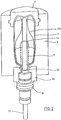
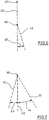
- the basic structure of a device for forming preforms (1) in container (2) is in Fig. 1 and in Fig. 2 shown.
- the device for forming the container (2) consists essentially of a blowing station (3), which is provided with a blow mold (4) into which a preform (1) can be inserted.
- the preform (1) may be a polyethylene terephthalate injection-molded part.
- the blow mold (4) consists of mold halves (5, 6) and a bottom part (7), which is a lifting device (8) is positionable.
- the preform (1) can be held in the region of the blowing station (3) by a transport mandrel (9) which, together with the preform (1), passes through a plurality of treatment stations within the device. But it is also possible to insert the preform (1) directly into the blow mold (4), for example via tongs or other handling means.
- a connecting piston (10) is arranged, which feeds the preform (1) compressed air and at the same time makes a seal relative to the transport mandrel (9).
- a connecting piston (10) is arranged, which feeds the preform (1) compressed air and at the same time makes a seal relative to the transport mandrel (9).
- a stretch rod (11) which is positioned by a cylinder (12).
- the use of curve segments is particularly useful when a plurality of blowing stations (3) are arranged on a rotating blowing wheel.
- a use of cylinders (12) is expedient if stationarily arranged blowing stations (3) are provided.
- the stretching system is designed such that a tandem arrangement of two cylinders (12) is provided. From a primary cylinder (13), the stretch rod (11) is first moved to the area of a bottom (14) of the preform (1) before the beginning of the actual stretching operation.
- the primary cylinder (13) with extended stretching rod together with a carriage (15) carrying the primary cylinder (13) is positioned by a secondary cylinder (16) or via a cam control.
- the secondary cylinder (16) in such a cam-controlled manner that a current stretching position is predetermined by a guide roller (17) which slides along a curved path during the execution of the stretching operation.
- the guide roller (17) is pressed by the secondary cylinder (16) against the guideway.
- the carriage (15) slides along two guide elements (18).
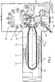
- Fig. 2 shows in addition to the blown container (2) and dashed lines drawn the preform (1) and schematically a developing container bladder (23).
- Fig. 3 shows the basic structure of a blow molding machine, which is provided with a heating section (24) and a rotating blowing wheel (25).
- a preform input (26) the preforms (1) are transported by transfer wheels (27, 28, 29) into the region of the heating path (24).
- heating radiator (30) and blower (31) are arranged to temper the preforms (1).
- blowing wheel (25) After a sufficient temperature control of the preforms (1), they are transferred to the blowing wheel (25), in the region of which the blowing stations (3) are arranged.
- the finished blown containers (2) are fed by further transfer wheels to a delivery line (32).
- thermoplastic material different plastics can be used.
- PET, PEN or PP can be used.
- the expansion of the preform (1) during the orientation process is carried out by compressed air supply.
- the compressed air supply is in a Vorblasphase in which gas, for example, compressed air, is supplied at a low pressure level and divided into a subsequent Hauptblasphase in which gas is supplied at a higher pressure level.
- gas for example, compressed air
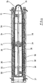
- the heating section (24) is formed of a plurality of revolving transport elements (33) which are strung together like a chain and guided by guide wheels (34).
- guide wheels (34) In particular, it is envisaged to open a substantially rectangular basic contour by the chain-like arrangement.
- the heating section (24) in the region of the transfer wheel (29) and an input wheel (35) facing extension of the heating section (24) a single relatively large-sized guide wheel (34) and in the region of adjacent deflections two comparatively smaller dimensioned guide wheels (36) used , In principle, however, any other guides are conceivable.
- the arrangement shown to be particularly useful since in the region of the corresponding extent of the heating section (24) three deflecting wheels (34, 36) are positioned, and although in each case the smaller deflection wheels (36) in the region of the transition to the linear curves of the heating section (24) and the larger deflection wheel (34) in the immediate transfer area to the transfer wheel (29) and the input wheel (35).
- chain-like transport elements (33) it is for example also possible to use a rotating heating wheel.
- modified heating section (24) can be tempered by the larger number of radiant heaters (30) a larger amount of preforms (1) per unit time.
- the fans (31) introduce cooling air into the region of cooling air ducts (39), which in each case oppose the associated radiant heaters (30) and emit the cooling air via outflow openings.
- the arrangement of the outflow directions, a flow direction for the cooling air is realized substantially transversely to a transport direction of the preforms (1).
- the cooling air ducts (39) can provide reflectors for the heating radiation in the area opposite the radiant heaters (30), and it is likewise possible to realize cooling of the radiant heaters (30) via the discharged cooling air.
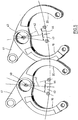
- Fig. 5 illustrates the arrangement of mold carriers (19, 20) with each other in an open state of the blowing station (3) partially overlapping mold carriers (19, 20).
- the mold carriers (19, 20) ribs, which are arranged at a different height level.
- the mold carriers (19, 20) are arranged pivotable relative to the axis of rotation (40) of the blowing station (3). The pivoting can be controlled by a steering lever (41).
- the mold supports (19) Relative to a parting plane (42) of the blowing station (3), the mold supports (19) have opening angles (43, 44). In one illustrated embodiment, the opening angles (43, 44) are different relative to one another.
- Fig. 6 shows a schematic representation of a further embodiment.
- the parting plane (42) is inclined with respect to a radially extending reference plane (45) of the blowing wheel (25) with an inclination angle (46).
- the reference plane (45) extends through an axis of rotation (47) of the blowing wheel (25) and through the axis of rotation (40) of the mold carriers (19, 20) of the blowing station (3).
- a corresponding oblique arrangement of the parting plane (42) also supports reduced opening angles (43, 44) of the blowing stations (3).
- the relative to the reference plane (45) inclined arrangement of the parting plane (42) can be implemented statically or only for certain periods of time dynamically. A dynamic realization can be achieved, for example, by a pivotable arrangement of the blowing stations (3).
- Fig. 7 illustrates again the realization relative to each other different opening angle (43, 44).
- the different opening angles (43) can be realized, for example, by a movement of the mold carriers (19, 20) which is in the same direction but at different speeds with respect to the parting plane (42).
- the mold carriers (19, 20) are rigidly coupled with respect to their motion control.
Landscapes
- Engineering & Computer Science (AREA)
- Manufacturing & Machinery (AREA)
- Mechanical Engineering (AREA)
- Blow-Moulding Or Thermoforming Of Plastics Or The Like (AREA)
- Moulds For Moulding Plastics Or The Like (AREA)
Claims (9)
- Dispositif de moulage par soufflage de récipients (2) présentant au moins deux stations de soufflage (3) agencées sur une roue de soufflage (25) pour la transformation de préformes (1) thermoplastiques en récipients (2), et dont chaque stations de soufflage (3) est équipée d'au moins deux segments de moule de soufflage maintenus par des supports de moule (19, 20), et dont les segments de moule de soufflage, lorsque la station de soufflage (3) est en état fermé, sont agencés le long d'un plan de joint (42) et fixés l'un par rapport à l'autre par au moins un élément de verrouillage, un support de moule (19, 20) au moins d'au moins une station de soufflage (3) s'étendant, lors d'au moins un état opérationnel, dans une zone qui chevauche une zone de référence définie par un volume d'un même support de moule (19, 20) d'une station de soufflage (3) voisine symétrisé par rapport à un plan médian radial (45), ce volume étant, lors de la symétrisation, placé en un positionnement d'ouverture maximale (43, 44), caractérisé en ce que le plan médian (45) passe par un axe de rotation (47) de la roue de soufflage (25) et un axe de rotation (40) des supports de moule (19, 20), les supports de moule (19, 20) voisins se chevauchant au niveau de nervurages agencés à des niveaux de hauteur différents l'un par rapport à l'autre.
- Dispositif selon la revendication 1, caractérisé en ce que, en un positionnement d'ouverture au moins, des support de moule (19, 20) voisins se chevauchent au moins en partie.
- Dispositif selon l'une des revendications 1 ou 2, caractérisé en ce que les support de moule (19, 20) présentent, par rapport à un plan de joint (20), des angles d'ouverture (43, 44) différents l'un par rapport à l'autre.
- Dispositif selon l'une des revendications 1 à 3, caractérisé en ce que par rapport au plan de joint (42), les support de moule (19, 20) sont accouplés et peuvent être positionnés en sens inverse.
- Dispositif selon l'une des revendications 1 à 3, caractérisé en ce que, par rapport au plan de joint (42), les support de moule (19, 20) sont agencés de façon à pouvoir être positionnés l'un par rapport à l'autre et indépendamment d'un de l'autre.
- Dispositif selon l'une des revendications 1 à 5, caractérisé en ce que le plan de joint (42) est agencé de façon à former un angle d'inclinaison (46) par rapport à un plan de référence (45) d'orientation radiale.
- Dispositif selon la revendication 6, caractérisé en ce que le plan de joint (42) est agencé de façon à former un angle d'inclinaison (46) constant par rapport au plan de référence (45).
- Dispositif selon la revendication 6, caractérisé en ce que l'angle d'inclinaison (46) est variable dans le temps.
- Dispositif selon l'une des revendications 1 à 8, caractérisé en ce que la station de soufflage (3) est agencée de façon à pouvoir pivoter.
Priority Applications (1)
| Application Number | Priority Date | Filing Date | Title |
|---|---|---|---|
| PL04022882T PL1520681T3 (pl) | 2003-10-04 | 2004-09-24 | Urządzenie do formowania pojemników przez rozdmuchiwanie |
Applications Claiming Priority (2)
| Application Number | Priority Date | Filing Date | Title |
|---|---|---|---|
| DE10346089 | 2003-10-04 | ||
| DE10346089A DE10346089A1 (de) | 2003-10-04 | 2003-10-04 | Vorrichtung zur Blasformung von Behältern |
Publications (3)
| Publication Number | Publication Date |
|---|---|
| EP1520681A1 EP1520681A1 (fr) | 2005-04-06 |
| EP1520681B1 EP1520681B1 (fr) | 2006-05-17 |
| EP1520681B2 true EP1520681B2 (fr) | 2016-12-21 |
Family
ID=34306251
Family Applications (1)
| Application Number | Title | Priority Date | Filing Date |
|---|---|---|---|
| EP04022882.7A Expired - Lifetime EP1520681B2 (fr) | 2003-10-04 | 2004-09-24 | Dispositif pour mouler par soufflage des corps creux en matière thermoplastique |
Country Status (6)
| Country | Link |
|---|---|
| EP (1) | EP1520681B2 (fr) |
| CN (1) | CN100493886C (fr) |
| AT (1) | ATE326331T1 (fr) |
| DE (2) | DE10346089A1 (fr) |
| ES (1) | ES2264785T3 (fr) |
| PL (1) | PL1520681T3 (fr) |
Cited By (1)
| Publication number | Priority date | Publication date | Assignee | Title |
|---|---|---|---|---|
| US12170849B2 (en) | 2022-02-04 | 2024-12-17 | Applied Materials, Inc. | Pulsed illumination for fluid inspection |
Families Citing this family (9)
| Publication number | Priority date | Publication date | Assignee | Title |
|---|---|---|---|---|
| FR2878184B1 (fr) * | 2004-11-19 | 2007-03-02 | Sidel Sas | Dispositif de moulage pour la fabrication de recipients en materiau thermoplastique |
| FR2881678B1 (fr) * | 2005-02-08 | 2009-04-24 | Sidel Sas | Procede de commande d'ouverture et de fermeture d'un moule de soufflage et dispositif de soufflage agence pour sa mise en oeuvre |
| DE102005034541A1 (de) * | 2005-07-23 | 2007-02-01 | Sig Technology Ltd. | Verfahren und Vorrichtung zur Blasformung von Behältern |
| DE102007022638A1 (de) * | 2007-05-15 | 2008-11-20 | Sig Technology Ag | Vorrichtung zur Blasformung von Behältern |
| DE102008029531A1 (de) * | 2008-06-21 | 2009-12-24 | Krones Ag | Verfahren und Vorrichtung zum Einsetzen eines Vorformlings in und zur Entnahme einer Flasche aus einer Blasmaschine |
| DE102009049260A1 (de) | 2009-10-13 | 2011-04-21 | Krones Ag | Formträger mit Antriebseinrichtung |
| FR2969955B1 (fr) * | 2011-01-04 | 2013-02-01 | Serac Group | Dispositif de soufflage de recipients |
| CN102765185B (zh) * | 2012-07-28 | 2015-09-09 | 台州迈格机械模具有限公司 | 夹胚机械手 |
| CN103171126B (zh) * | 2013-03-19 | 2015-07-01 | 江苏新美星包装机械股份有限公司 | 一种吹瓶机 |
Citations (1)
| Publication number | Priority date | Publication date | Assignee | Title |
|---|---|---|---|---|
| US4035463A (en) † | 1968-01-16 | 1977-07-12 | Heidenreich & Harbeck | Method of making hollow articles, especially bottles, of thermoplastics |
Family Cites Families (3)
| Publication number | Priority date | Publication date | Assignee | Title |
|---|---|---|---|---|
| FR2793722B1 (fr) * | 1999-05-17 | 2001-08-03 | Sidel Sa | Machine de soufflage comportant un mecanisme de fermeture et de verrouillage combines d'une unite de moulage |
| DE19948474B4 (de) * | 1999-10-08 | 2012-05-24 | Khs Corpoplast Gmbh | Verfahren und Vorrichtung zur Blasformung von Behältern |
| IT1313996B1 (it) * | 1999-11-18 | 2002-12-03 | Smi Spa | Macchina rotativa per la produzione di contenitori o di bottiglie diplastica per soffiaggio a partire da una preforma stampata e stampo |
-
2003
- 2003-10-04 DE DE10346089A patent/DE10346089A1/de not_active Withdrawn
-
2004
- 2004-09-24 PL PL04022882T patent/PL1520681T3/pl unknown
- 2004-09-24 AT AT04022882T patent/ATE326331T1/de active
- 2004-09-24 ES ES04022882T patent/ES2264785T3/es not_active Expired - Lifetime
- 2004-09-24 EP EP04022882.7A patent/EP1520681B2/fr not_active Expired - Lifetime
- 2004-09-24 DE DE502004000575T patent/DE502004000575D1/de not_active Expired - Lifetime
- 2004-09-30 CN CNB2004100757408A patent/CN100493886C/zh not_active Expired - Lifetime
Patent Citations (1)
| Publication number | Priority date | Publication date | Assignee | Title |
|---|---|---|---|---|
| US4035463A (en) † | 1968-01-16 | 1977-07-12 | Heidenreich & Harbeck | Method of making hollow articles, especially bottles, of thermoplastics |
Cited By (1)
| Publication number | Priority date | Publication date | Assignee | Title |
|---|---|---|---|---|
| US12170849B2 (en) | 2022-02-04 | 2024-12-17 | Applied Materials, Inc. | Pulsed illumination for fluid inspection |
Also Published As
| Publication number | Publication date |
|---|---|
| ES2264785T3 (es) | 2007-01-16 |
| CN100493886C (zh) | 2009-06-03 |
| EP1520681A1 (fr) | 2005-04-06 |
| EP1520681B1 (fr) | 2006-05-17 |
| DE502004000575D1 (de) | 2006-06-22 |
| PL1520681T3 (pl) | 2006-11-30 |
| DE10346089A1 (de) | 2005-05-12 |
| CN1651221A (zh) | 2005-08-10 |
| ATE326331T1 (de) | 2006-06-15 |
Similar Documents
| Publication | Publication Date | Title |
|---|---|---|
| EP2139665B1 (fr) | Procédé et dispositif de moulage par soufflage de récipients | |
| EP2144742B1 (fr) | Dispositif de moulage par soufflage de récipients | |
| EP2429795B1 (fr) | Procédé et dispositif pour le moulage par soufflage et le remplissage de récipients | |
| EP1789247B1 (fr) | Dispositif de moulage par souffler de récipients | |
| EP1871590B1 (fr) | Procede et dispositif pour mouler des recipients par soufflage | |
| EP1907190B1 (fr) | Procede et dispositif de soufflage de recipients | |
| EP1535719B1 (fr) | Dispositif pour mouler des récipients par soufflage | |
| EP1520681B2 (fr) | Dispositif pour mouler par soufflage des corps creux en matière thermoplastique | |
| EP1350612B1 (fr) | Appareil pour le transport de préformes / paraisons avec des pinces controlables séparement et fixées radialement sur une disque tournante / rotative | |
| EP1226017B1 (fr) | Procede et dispositif de formage par soufflage de contenants | |
| EP2694270B1 (fr) | Dispositif pour le moulage de recipients par soufflage | |
| EP1773571B1 (fr) | Procede et dispositif pour former des contenants par soufflage | |
| EP1732743B1 (fr) | Procede et dispositif de moulage de contenants par soufflage, faisant appel a une vitesse d'augmentation de pression reduite | |
| EP1297942B1 (fr) | Dispositif pour la manipulation de récipients moulés par étirage soufflage utilisant une roue de transfert, où un moyen de retenue est orientable par rapport à un bras de support et contrôlé par une came | |
| EP1566258B1 (fr) | Appareil pour l'usinage de pièces | |
| EP1535720B1 (fr) | Dispositif pour moulage par soufflage d' articles | |
| EP1473139B1 (fr) | Procédé et appareil de formage de récipients par soufflage | |
| WO2007033631A2 (fr) | Procede et dispositif pour le moulage par soufflage de contenants | |
| EP2129508B1 (fr) | Procédé de moulage par soufflage de contenants | |
| DE102005008685A1 (de) | Verfahren und Vorrichtung zur Blasformung von Behältern | |
| WO2012116684A1 (fr) | Procédé et dispositif pour la manipulation d'ébauches | |
| EP2768654B1 (fr) | Dispositif de retenue de pièces | |
| DE102024104932A1 (de) | Verfahren und Vorrichtung zum Herstellen von Behältern aus Vorformlingen aus einem thermoplastischen Material mit hoher Produktionsleistung | |
| DE102006004940A1 (de) | Verfahren und Vorrichtung zur Blasformung von Behältern | |
| WO2001039958A1 (fr) | Procede et dispositif de moulage par soufflage de recipients |
Legal Events
| Date | Code | Title | Description |
|---|---|---|---|
| PUAI | Public reference made under article 153(3) epc to a published international application that has entered the european phase |
Free format text: ORIGINAL CODE: 0009012 |
|
| AK | Designated contracting states |
Kind code of ref document: A1 Designated state(s): AT BE BG CH CY CZ DE DK EE ES FI FR GB GR HU IE IT LI LU MC NL PL PT RO SE SI SK TR |
|
| AX | Request for extension of the european patent |
Extension state: AL HR LT LV MK |
|
| 17P | Request for examination filed |
Effective date: 20050408 |
|
| GRAP | Despatch of communication of intention to grant a patent |
Free format text: ORIGINAL CODE: EPIDOSNIGR1 |
|
| AKX | Designation fees paid |
Designated state(s): AT BE BG CH CY CZ DE DK EE ES FI FR GB GR HU IE IT LI LU MC NL PL PT RO SE SI SK TR |
|
| GRAS | Grant fee paid |
Free format text: ORIGINAL CODE: EPIDOSNIGR3 |
|
| GRAA | (expected) grant |
Free format text: ORIGINAL CODE: 0009210 |
|
| AK | Designated contracting states |
Kind code of ref document: B1 Designated state(s): AT BE BG CH CY CZ DE DK EE ES FI FR GB GR HU IE IT LI LU MC NL PL PT RO SE SI SK TR |
|
| PG25 | Lapsed in a contracting state [announced via postgrant information from national office to epo] |
Ref country code: IE Free format text: LAPSE BECAUSE OF FAILURE TO SUBMIT A TRANSLATION OF THE DESCRIPTION OR TO PAY THE FEE WITHIN THE PRESCRIBED TIME-LIMIT Effective date: 20060517 Ref country code: NL Free format text: LAPSE BECAUSE OF FAILURE TO SUBMIT A TRANSLATION OF THE DESCRIPTION OR TO PAY THE FEE WITHIN THE PRESCRIBED TIME-LIMIT Effective date: 20060517 Ref country code: RO Free format text: LAPSE BECAUSE OF FAILURE TO SUBMIT A TRANSLATION OF THE DESCRIPTION OR TO PAY THE FEE WITHIN THE PRESCRIBED TIME-LIMIT Effective date: 20060517 Ref country code: SI Free format text: LAPSE BECAUSE OF FAILURE TO SUBMIT A TRANSLATION OF THE DESCRIPTION OR TO PAY THE FEE WITHIN THE PRESCRIBED TIME-LIMIT Effective date: 20060517 Ref country code: FI Free format text: LAPSE BECAUSE OF FAILURE TO SUBMIT A TRANSLATION OF THE DESCRIPTION OR TO PAY THE FEE WITHIN THE PRESCRIBED TIME-LIMIT Effective date: 20060517 Ref country code: SK Free format text: LAPSE BECAUSE OF FAILURE TO SUBMIT A TRANSLATION OF THE DESCRIPTION OR TO PAY THE FEE WITHIN THE PRESCRIBED TIME-LIMIT Effective date: 20060517 Ref country code: CZ Free format text: LAPSE BECAUSE OF FAILURE TO SUBMIT A TRANSLATION OF THE DESCRIPTION OR TO PAY THE FEE WITHIN THE PRESCRIBED TIME-LIMIT Effective date: 20060517 |
|
| REG | Reference to a national code |
Ref country code: GB Ref legal event code: FG4D Free format text: NOT ENGLISH |
|
| REG | Reference to a national code |
Ref country code: CH Ref legal event code: EP |
|
| REG | Reference to a national code |
Ref country code: IE Ref legal event code: FG4D Free format text: LANGUAGE OF EP DOCUMENT: GERMAN |
|
| REF | Corresponds to: |
Ref document number: 502004000575 Country of ref document: DE Date of ref document: 20060622 Kind code of ref document: P |
|
| PG25 | Lapsed in a contracting state [announced via postgrant information from national office to epo] |
Ref country code: DK Free format text: LAPSE BECAUSE OF FAILURE TO SUBMIT A TRANSLATION OF THE DESCRIPTION OR TO PAY THE FEE WITHIN THE PRESCRIBED TIME-LIMIT Effective date: 20060817 Ref country code: SE Free format text: LAPSE BECAUSE OF FAILURE TO SUBMIT A TRANSLATION OF THE DESCRIPTION OR TO PAY THE FEE WITHIN THE PRESCRIBED TIME-LIMIT Effective date: 20060817 |
|
| GBT | Gb: translation of ep patent filed (gb section 77(6)(a)/1977) |
Effective date: 20060904 |
|
| PG25 | Lapsed in a contracting state [announced via postgrant information from national office to epo] |
Ref country code: BE Free format text: LAPSE BECAUSE OF NON-PAYMENT OF DUE FEES Effective date: 20060930 Ref country code: MC Free format text: LAPSE BECAUSE OF NON-PAYMENT OF DUE FEES Effective date: 20060930 |
|
| REG | Reference to a national code |
Ref country code: CH Ref legal event code: NV Representative=s name: PA ALDO ROEMPLER |
|
| PG25 | Lapsed in a contracting state [announced via postgrant information from national office to epo] |
Ref country code: PT Free format text: LAPSE BECAUSE OF FAILURE TO SUBMIT A TRANSLATION OF THE DESCRIPTION OR TO PAY THE FEE WITHIN THE PRESCRIBED TIME-LIMIT Effective date: 20061017 |
|
| NLV1 | Nl: lapsed or annulled due to failure to fulfill the requirements of art. 29p and 29m of the patents act | ||
| REG | Reference to a national code |
Ref country code: IE Ref legal event code: FD4D |
|
| REG | Reference to a national code |
Ref country code: ES Ref legal event code: FG2A Ref document number: 2264785 Country of ref document: ES Kind code of ref document: T3 |
|
| ET | Fr: translation filed | ||
| PLBI | Opposition filed |
Free format text: ORIGINAL CODE: 0009260 |
|
| PLAX | Notice of opposition and request to file observation + time limit sent |
Free format text: ORIGINAL CODE: EPIDOSNOBS2 |
|
| PLBB | Reply of patent proprietor to notice(s) of opposition received |
Free format text: ORIGINAL CODE: EPIDOSNOBS3 |
|
| 26 | Opposition filed |
Opponent name: KRONES AKTIENGESELLSCHAFT Effective date: 20070216 |
|
| BERE | Be: lapsed |
Owner name: SIG TECHNOLOGY LTD. Effective date: 20060930 |
|
| PG25 | Lapsed in a contracting state [announced via postgrant information from national office to epo] |
Ref country code: GR Free format text: LAPSE BECAUSE OF FAILURE TO SUBMIT A TRANSLATION OF THE DESCRIPTION OR TO PAY THE FEE WITHIN THE PRESCRIBED TIME-LIMIT Effective date: 20060818 |
|
| PG25 | Lapsed in a contracting state [announced via postgrant information from national office to epo] |
Ref country code: BG Free format text: LAPSE BECAUSE OF FAILURE TO SUBMIT A TRANSLATION OF THE DESCRIPTION OR TO PAY THE FEE WITHIN THE PRESCRIBED TIME-LIMIT Effective date: 20060817 Ref country code: EE Free format text: LAPSE BECAUSE OF FAILURE TO SUBMIT A TRANSLATION OF THE DESCRIPTION OR TO PAY THE FEE WITHIN THE PRESCRIBED TIME-LIMIT Effective date: 20060517 |
|
| PG25 | Lapsed in a contracting state [announced via postgrant information from national office to epo] |
Ref country code: HU Free format text: LAPSE BECAUSE OF FAILURE TO SUBMIT A TRANSLATION OF THE DESCRIPTION OR TO PAY THE FEE WITHIN THE PRESCRIBED TIME-LIMIT Effective date: 20061118 Ref country code: LU Free format text: LAPSE BECAUSE OF NON-PAYMENT OF DUE FEES Effective date: 20060924 Ref country code: TR Free format text: LAPSE BECAUSE OF FAILURE TO SUBMIT A TRANSLATION OF THE DESCRIPTION OR TO PAY THE FEE WITHIN THE PRESCRIBED TIME-LIMIT Effective date: 20060517 |
|
| REG | Reference to a national code |
Ref country code: CH Ref legal event code: PCAR Free format text: ALDO ROEMPLER PATENTANWALT;BRENDENWEG 11 POSTFACH 154;9424 RHEINECK (CH) |
|
| PGFP | Annual fee paid to national office [announced via postgrant information from national office to epo] |
Ref country code: ES Payment date: 20080714 Year of fee payment: 5 |
|
| PG25 | Lapsed in a contracting state [announced via postgrant information from national office to epo] |
Ref country code: CY Free format text: LAPSE BECAUSE OF FAILURE TO SUBMIT A TRANSLATION OF THE DESCRIPTION OR TO PAY THE FEE WITHIN THE PRESCRIBED TIME-LIMIT Effective date: 20060517 |
|
| PGFP | Annual fee paid to national office [announced via postgrant information from national office to epo] |
Ref country code: PL Payment date: 20080710 Year of fee payment: 5 |
|
| PGFP | Annual fee paid to national office [announced via postgrant information from national office to epo] |
Ref country code: GB Payment date: 20080910 Year of fee payment: 5 |
|
| PGFP | Annual fee paid to national office [announced via postgrant information from national office to epo] |
Ref country code: CH Payment date: 20081209 Year of fee payment: 5 |
|
| RAP2 | Party data changed (patent owner data changed or rights of a patent transferred) |
Owner name: KHS CORPOPLAST GMBH & CO. KG |
|
| REG | Reference to a national code |
Ref country code: FR Ref legal event code: TP |
|
| REG | Reference to a national code |
Ref country code: CH Ref legal event code: PL |
|
| GBPC | Gb: european patent ceased through non-payment of renewal fee |
Effective date: 20090924 |
|
| PG25 | Lapsed in a contracting state [announced via postgrant information from national office to epo] |
Ref country code: LI Free format text: LAPSE BECAUSE OF NON-PAYMENT OF DUE FEES Effective date: 20090930 Ref country code: CH Free format text: LAPSE BECAUSE OF NON-PAYMENT OF DUE FEES Effective date: 20090930 |
|
| PG25 | Lapsed in a contracting state [announced via postgrant information from national office to epo] |
Ref country code: GB Free format text: LAPSE BECAUSE OF NON-PAYMENT OF DUE FEES Effective date: 20090924 |
|
| PG25 | Lapsed in a contracting state [announced via postgrant information from national office to epo] |
Ref country code: PL Free format text: LAPSE BECAUSE OF NON-PAYMENT OF DUE FEES Effective date: 20090924 |
|
| REG | Reference to a national code |
Ref country code: PL Ref legal event code: LAPE |
|
| REG | Reference to a national code |
Ref country code: DE Ref legal event code: R081 Ref document number: 502004000575 Country of ref document: DE Owner name: KHS CORPOPLAST GMBH, DE Free format text: FORMER OWNER: KHS CORPOPLAST GMBH & CO. KG, 20539 HAMBURG, DE Effective date: 20110504 |
|
| REG | Reference to a national code |
Ref country code: ES Ref legal event code: FD2A Effective date: 20110711 |
|
| PG25 | Lapsed in a contracting state [announced via postgrant information from national office to epo] |
Ref country code: ES Free format text: LAPSE BECAUSE OF NON-PAYMENT OF DUE FEES Effective date: 20110629 |
|
| PLAY | Examination report in opposition despatched + time limit |
Free format text: ORIGINAL CODE: EPIDOSNORE2 |
|
| PG25 | Lapsed in a contracting state [announced via postgrant information from national office to epo] |
Ref country code: ES Free format text: LAPSE BECAUSE OF NON-PAYMENT OF DUE FEES Effective date: 20090925 |
|
| PLBC | Reply to examination report in opposition received |
Free format text: ORIGINAL CODE: EPIDOSNORE3 |
|
| PLAY | Examination report in opposition despatched + time limit |
Free format text: ORIGINAL CODE: EPIDOSNORE2 |
|
| PLBP | Opposition withdrawn |
Free format text: ORIGINAL CODE: 0009264 |
|
| PLAH | Information related to despatch of examination report in opposition + time limit modified |
Free format text: ORIGINAL CODE: EPIDOSCORE2 |
|
| PLBC | Reply to examination report in opposition received |
Free format text: ORIGINAL CODE: EPIDOSNORE3 |
|
| PLAY | Examination report in opposition despatched + time limit |
Free format text: ORIGINAL CODE: EPIDOSNORE2 |
|
| PLAH | Information related to despatch of examination report in opposition + time limit modified |
Free format text: ORIGINAL CODE: EPIDOSCORE2 |
|
| PLBC | Reply to examination report in opposition received |
Free format text: ORIGINAL CODE: EPIDOSNORE3 |
|
| PLAB | Opposition data, opponent's data or that of the opponent's representative modified |
Free format text: ORIGINAL CODE: 0009299OPPO |
|
| REG | Reference to a national code |
Ref country code: DE Ref legal event code: R082 Ref document number: 502004000575 Country of ref document: DE Representative=s name: MEISSNER BOLTE PATENTANWAELTE RECHTSANWAELTE P, DE Ref country code: DE Ref legal event code: R082 Ref document number: 502004000575 Country of ref document: DE |
|
| REG | Reference to a national code |
Ref country code: FR Ref legal event code: PLFP Year of fee payment: 13 |
|
| PUAH | Patent maintained in amended form |
Free format text: ORIGINAL CODE: 0009272 |
|
| STAA | Information on the status of an ep patent application or granted ep patent |
Free format text: STATUS: PATENT MAINTAINED AS AMENDED |
|
| RAP2 | Party data changed (patent owner data changed or rights of a patent transferred) |
Owner name: KHS CORPOPLAST GMBH |
|
| REG | Reference to a national code |
Ref country code: DE Ref legal event code: R082 Ref document number: 502004000575 Country of ref document: DE Ref country code: DE Ref legal event code: R082 Ref document number: 502004000575 Country of ref document: DE Representative=s name: EISENFUEHR SPEISER PATENTANWAELTE RECHTSANWAEL, DE |
|
| 27A | Patent maintained in amended form |
Effective date: 20161221 |
|
| AK | Designated contracting states |
Kind code of ref document: B2 Designated state(s): AT BE BG CH CY CZ DE DK EE ES FI FR GB GR HU IE IT LI LU MC NL PL PT RO SE SI SK TR |
|
| REG | Reference to a national code |
Ref country code: DE Ref legal event code: R102 Ref document number: 502004000575 Country of ref document: DE |
|
| REG | Reference to a national code |
Ref country code: FR Ref legal event code: PLFP Year of fee payment: 14 |
|
| REG | Reference to a national code |
Ref country code: AT Ref legal event code: PC Ref document number: 326331 Country of ref document: AT Kind code of ref document: T Owner name: KHS CORPOPLAST GMBH, DE Effective date: 20180417 |
|
| REG | Reference to a national code |
Ref country code: FR Ref legal event code: PLFP Year of fee payment: 15 |
|
| REG | Reference to a national code |
Ref country code: DE Ref legal event code: R082 Ref document number: 502004000575 Country of ref document: DE Representative=s name: EISENFUEHR SPEISER PATENTANWAELTE RECHTSANWAEL, DE |
|
| REG | Reference to a national code |
Ref country code: DE Ref legal event code: R082 Ref document number: 502004000575 Country of ref document: DE Representative=s name: EISENFUEHR SPEISER PATENTANWAELTE RECHTSANWAEL, DE Ref country code: DE Ref legal event code: R081 Ref document number: 502004000575 Country of ref document: DE Owner name: KHS GMBH, DE Free format text: FORMER OWNER: KHS CORPOPLAST GMBH, 22145 HAMBURG, DE Ref country code: DE Ref legal event code: R082 Ref document number: 502004000575 Country of ref document: DE |
|
| REG | Reference to a national code |
Ref country code: DE Ref legal event code: R082 Ref document number: 502004000575 Country of ref document: DE Representative=s name: EISENFUEHR SPEISER PATENTANWAELTE RECHTSANWAEL, DE |
|
| REG | Reference to a national code |
Ref country code: AT Ref legal event code: PC Ref document number: 326331 Country of ref document: AT Kind code of ref document: T Owner name: KHS GMBH, DE Effective date: 20220921 |
|
| PGFP | Annual fee paid to national office [announced via postgrant information from national office to epo] |
Ref country code: AT Payment date: 20230921 Year of fee payment: 20 |
|
| PGFP | Annual fee paid to national office [announced via postgrant information from national office to epo] |
Ref country code: FR Payment date: 20230927 Year of fee payment: 20 Ref country code: DE Payment date: 20230920 Year of fee payment: 20 |
|
| PGFP | Annual fee paid to national office [announced via postgrant information from national office to epo] |
Ref country code: IT Payment date: 20230927 Year of fee payment: 20 |
|
| REG | Reference to a national code |
Ref country code: DE Ref legal event code: R071 Ref document number: 502004000575 Country of ref document: DE |
|
| REG | Reference to a national code |
Ref country code: AT Ref legal event code: MK07 Ref document number: 326331 Country of ref document: AT Kind code of ref document: T Effective date: 20240924 |