US7347313B2 - Method of equally spacing items in article handling systems - Google Patents
Method of equally spacing items in article handling systems Download PDFInfo
- Publication number
- US7347313B2 US7347313B2 US11/087,505 US8750505A US7347313B2 US 7347313 B2 US7347313 B2 US 7347313B2 US 8750505 A US8750505 A US 8750505A US 7347313 B2 US7347313 B2 US 7347313B2
- Authority
- US
- United States
- Prior art keywords
- gear mechanism
- items
- item
- path
- bars
- Prior art date
- Legal status (The legal status is an assumption and is not a legal conclusion. Google has not performed a legal analysis and makes no representation as to the accuracy of the status listed.)
- Expired - Fee Related, expires
Links
Images


Classifications
-
- B—PERFORMING OPERATIONS; TRANSPORTING
- B65—CONVEYING; PACKING; STORING; HANDLING THIN OR FILAMENTARY MATERIAL
- B65G—TRANSPORT OR STORAGE DEVICES, e.g. CONVEYORS FOR LOADING OR TIPPING, SHOP CONVEYOR SYSTEMS OR PNEUMATIC TUBE CONVEYORS
- B65G47/00—Article or material-handling devices associated with conveyors; Methods employing such devices
- B65G47/22—Devices influencing the relative position or the attitude of articles during transit by conveyors
- B65G47/26—Devices influencing the relative position or the attitude of articles during transit by conveyors arranging the articles, e.g. varying spacing between individual articles
- B65G47/30—Devices influencing the relative position or the attitude of articles during transit by conveyors arranging the articles, e.g. varying spacing between individual articles during transit by a series of conveyors
- B65G47/32—Applications of transfer devices
-
- B—PERFORMING OPERATIONS; TRANSPORTING
- B65—CONVEYING; PACKING; STORING; HANDLING THIN OR FILAMENTARY MATERIAL
- B65G—TRANSPORT OR STORAGE DEVICES, e.g. CONVEYORS FOR LOADING OR TIPPING, SHOP CONVEYOR SYSTEMS OR PNEUMATIC TUBE CONVEYORS
- B65G47/00—Article or material-handling devices associated with conveyors; Methods employing such devices
- B65G47/22—Devices influencing the relative position or the attitude of articles during transit by conveyors
- B65G47/26—Devices influencing the relative position or the attitude of articles during transit by conveyors arranging the articles, e.g. varying spacing between individual articles
Definitions
- the various embodiments described herein generally relate to positioning items. More particularly, the various embodiments relate to a method for equally spacing items within handling systems.
- the handling system may include applications in postal automation with the items to be spaced being mail containers and the like.
- the throughput and the efficiency of article handling systems may be substantially improved if more than one article is handled simultaneously.
- a stationary processing station may pick up several articles, at the same time, from a conveying system transporting the articles to the processing station.
- the conveying system may have platforms, slots or containers, which do not move with respect to each other and are equally spaced, to transport the articles.
- the conveying system may have a plurality of transport devices that move independently from each other on a track system to and from the processing station. The transport devices may be individually controlled to provide for the required equal spacing of the article carrying platforms, slots or containers at the processing station. This, however, may be time consuming and requires more effort and, as such, slow down the handling process.
- one aspect involves a method of equally spacing a predetermined number of items along a first path.
- the method moves the items towards each other to minimize distances between the items, and engages a gear mechanism with each item.
- the gear mechanism includes crossed bars, wherein pairs of the bars are coupled at middle joints so that each pair of bars forms an X-shaped structure and opposite ends of an X-shaped structure are coupled at end joints to respective ends of neighboring X-shaped structures. Further, the method activates the gear mechanism so that the gear mechanism acts upon each item and moves each item along the first path a predetermined distance to equally space the items.
- the various embodiments described herein do not require an individual articulation of the items to equally space them.
- the gear mechanism acts as a single actuator that positions all items at the same time.
- the gear mechanism positions the items at various predetermined pitches. After use, the gear mechanism is completely removable from the items.
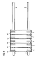
- FIG. 1 shows a schematic overview of an exemplary arrangement of items movable along a path
- FIG. 2 illustrates the arrangement of FIG. 1 in an initial position
- FIG. 3 illustrates one embodiment of a gear mechanism coupled to the arrangement in the initial position according to a first embodiment
- FIG. 4 illustrates the gear mechanism in an extended state according to the first embodiment
- FIG. 5 illustrates the arrangement of FIG. 1 in a final position with equally spaced items
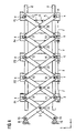
- FIG. 6 illustrates the gear mechanism in an extended state according to a second embodiment.
- the certain inventive embodiments described hereinafter generally position items in a desired manner, for example, so that neighboring items are equally spaced.
- items refer to devices, vehicles, articles, pieces, items or the like that are movable, for example, along a path. It is however contemplated that other items, as would be imagined by one skilled in the art, may be included in the definition of items. Further, it is contemplated that positioning such items may include positioning carriers or platforms that hold and/or carry these items.
- One exemplary application of these embodiments is in a system that handles such items.
- FIG. 1 shows five items P 1 , P 2 , P 3 , P 4 , P 5 that move from the right to the left side, as indicated by an arrow 3 .
- the number of items P i may be variable depending on a particular application.
- the items P 1 -P 5 have an elongated shape and extend across the two rails of the track 2 .
- each item P 1 -P 5 has in an area proximate to a rail a guide section 4 , as discussed below. That is, each item P 1 -P 2 has in the illustrated embodiment a pair of guide sections 4 . In that embodiment, the guide sections 4 are on one side of the items P 1 -P 5 . However, it is contemplated that the guide sections 4 may be located at other places (e.g., at corners or front sides) of the items P 1 -P 5 . The location of the guide sections 4 is selected to avoid any obstruction of the proper movement of the items P 1 -P 5 .
- the items P 1 -P 5 are in one embodiment randomly spaced at pitches A, B, C and D. That is, the pitch between item P 1 and item P 2 is A, the pitch between item P 2 and item P 3 is B, the pitch between item P 3 and item P 4 is C, and the pitch between item P 4 and item P 5 is D.
- the pitches A, B, C and D may be determined by the time an item P 1 -P 5 arrives at a processing station.
- FIG. 2 illustrates the arrangement of FIG. 1 in an initial position.
- the distances between the items P 1 -P 5 have been minimized by moving, for example, pushing the items P 1 -P 5 together.
- a distance exists between two neighboring items P 1 -P 5 .
- the distance may be substantially zero.
- E is the minimum possible pitch.
- FIG. 3 illustrates one embodiment of a gear mechanism 6 coupled to the arrangement in the initial position of FIG. 2 .
- the gear mechanism 6 includes a predetermined number of crossed bars 5 , wherein pairs of the bars 5 are coupled at middle joints 20 so that each pair of bars 5 forms an X-shaped structure and is movable similar to a scissors. Opposite ends of an X-shaped structure are coupled to respective ends of neighboring X-shaped structures by means of joints 12 , 14 .
- the joints 12 , 14 are configured to removably engage with the guide sections 4 of the items P 1 -P 5 so that the joints 12 , 14 may slide within the guide sections 4 .
- the joints 12 , 14 , 20 are configured to permit swiveling of the bars 5 .
- the gear mechanism 6 includes five X-shaped structures that are coupled through the joints 12 , 14 so that an XXXXX-structure results.
- the bars 5 are made of a material that provides sufficient rigidity and resists bending.
- the material may be metal or reinforced plastic. Further, the bars 5 may be flat bars or profiled bars that provide for the desired properties as to rigidity and bending.
- the bars 5 of an X-shaped structure are on one side coupled to a drive mechanism 8 , 10 by means of joints 16 , 18 and on the other side to a neighboring X-shaped structure by means of the joints 12 , 14 .
- the drive mechanism 8 , 10 is configured to move one or both joints 16 , 18 in the Y direction of a Cartesian (X-Y) coordinate system.
- the drive mechanism 8 , 10 does not move in the X direction and may be fixed at the driving end at or in proximity to the processing stations.
- the movement in the Y direction causes the joints 20 to move on a line parallel to the X axis so that the coupled X-shaped structures spread.
- the function of the gear mechanism 6 is similar to the function of Nuremberg scissors.
- FIG. 4 illustrates the embodiment of the gear mechanism 6 in an extended state, i.e., after the X-shaped structures have spread. While the joints 20 move in the X direction, the joints 12 , 14 move in X and Y directions. The joints 12 , 14 are configured to slide in the guide sections 4 and cause the items P 1 -P 5 to move in the X direction, as well. Each item P 1 -P 5 has an equal distance F to a neighboring item P 1 -P 5 .
- FIG. 5 illustrates the arrangement of FIG. 1 in a final position with equally spaced items P 1 -P 5 .
- the gear mechanism 6 has been removed from the items P 1 -P 5 .
- FIG. 6 illustrates the gear mechanism 6 in an extended state according to a second embodiment.
- the middle joints 20 are removably coupled to the items P 1 -P 5 instead of the joints 12 , 14 .
- the items P 1 -P 5 may not have guide sections 4 .
- the middle joints 20 ideally move along an axis parallel to the X axis, the middle joints 20 are configured to allow rotation but essentially no movement in Y direction.
- the method of placing items may be used in a mail processing system, which is one example of an article handling system.
- a mail processing system may process articles for delivery to millions of individual domestic addresses.
- Articles may include mail items, magazines, books and other items usually transported by the USPS.
- a mail processing system at a USPS processing site sorts all articles for the carriers and packages the sorted articles for each domestic address.
- the mail processing system is highly automated to handle the amount of daily articles. It includes a delivery point packaging (DPP) system that, for example, separates the articles, reads their destination addresses and groups the articles based upon their respective destination addresses.
- DPP delivery point packaging
- One example of a DPP system includes an arrangement of a multitude of individual pockets or slots for individual articles.
- a transport system transports the articles along a track system to the slots. Feeders insert the articles into the transport system at loading points. At this point, the destination address of an article is known and the transport system transports the article along a delivery path to a slot that is pre-assigned to the destination address of that article.
- the partitions (items) should be spaced equally before being lowered in the replenishment device. Therefore, all partitions that are to be replenished are pushed together so that the distance between the partitions is minimized, as illustrated in FIG. 2 .
- the gear mechanism 6 is coupled to each partition, as illustrated in FIG. 3 .
- the gear mechanism 6 is then expanded according to the desired distance between the replenishment devices. After the expansion, the partitions have the same spacing as the bags in which the partitions will be lowered.
Landscapes
- Engineering & Computer Science (AREA)
- Mechanical Engineering (AREA)
- Chain Conveyers (AREA)
- Attitude Control For Articles On Conveyors (AREA)
Abstract
To equally space items along a first path, a predetermined number of items is moved towards each other to minimize distances between the items, and a gear mechanism is engaged with each item. The gear mechanism includes crossed bars, wherein pairs of the bars are coupled at middle joints so that each pair of bars forms an X-shaped structure and opposite ends of an X-shaped structure are coupled at end joints to respective ends of neighboring X-shaped structures. The gear mechanism is activated so that the gear mechanism acts upon each item and moves each item along the first path a predetermined distance to equally space the items.
Description
The various embodiments described herein generally relate to positioning items. More particularly, the various embodiments relate to a method for equally spacing items within handling systems. The handling system may include applications in postal automation with the items to be spaced being mail containers and the like.
In various applications, for example, article handling systems, the throughput and the efficiency of article handling systems may be substantially improved if more than one article is handled simultaneously. For example, a stationary processing station may pick up several articles, at the same time, from a conveying system transporting the articles to the processing station. Some systems require that the articles are equally spaced from each other to enable simultaneous handling. In these systems, the conveying system may have platforms, slots or containers, which do not move with respect to each other and are equally spaced, to transport the articles. In other systems, the conveying system may have a plurality of transport devices that move independently from each other on a track system to and from the processing station. The transport devices may be individually controlled to provide for the required equal spacing of the article carrying platforms, slots or containers at the processing station. This, however, may be time consuming and requires more effort and, as such, slow down the handling process.
It is an objective of the present invention to improve the handling of items without individually controlling the transport devices at a processing station.
Accordingly, one aspect involves a method of equally spacing a predetermined number of items along a first path. The method moves the items towards each other to minimize distances between the items, and engages a gear mechanism with each item. The gear mechanism includes crossed bars, wherein pairs of the bars are coupled at middle joints so that each pair of bars forms an X-shaped structure and opposite ends of an X-shaped structure are coupled at end joints to respective ends of neighboring X-shaped structures. Further, the method activates the gear mechanism so that the gear mechanism acts upon each item and moves each item along the first path a predetermined distance to equally space the items.
Advantageously, the various embodiments described herein do not require an individual articulation of the items to equally space them. Instead, the gear mechanism acts as a single actuator that positions all items at the same time. In addition, the gear mechanism positions the items at various predetermined pitches. After use, the gear mechanism is completely removable from the items.
These and other aspects, advantages and novel features of the embodiments described herein will become apparent upon reading the following detailed description and upon reference to the accompanying drawings. In the drawings, same elements have the same reference numerals.
The certain inventive embodiments described hereinafter generally position items in a desired manner, for example, so that neighboring items are equally spaced. As used throughout the application items refer to devices, vehicles, articles, pieces, items or the like that are movable, for example, along a path. It is however contemplated that other items, as would be imagined by one skilled in the art, may be included in the definition of items. Further, it is contemplated that positioning such items may include positioning carriers or platforms that hold and/or carry these items. One exemplary application of these embodiments is in a system that handles such items.
The items P1-P5 are in one embodiment randomly spaced at pitches A, B, C and D. That is, the pitch between item P1 and item P2 is A, the pitch between item P2 and item P3 is B, the pitch between item P3 and item P4 is C, and the pitch between item P4 and item P5 is D. The pitches A, B, C and D may be determined by the time an item P1-P5 arrives at a processing station.
The bars 5 are made of a material that provides sufficient rigidity and resists bending. The material may be metal or reinforced plastic. Further, the bars 5 may be flat bars or profiled bars that provide for the desired properties as to rigidity and bending.
At a driving end (left hand side of FIG. 3 ), the bars 5 of an X-shaped structure are on one side coupled to a drive mechanism 8, 10 by means of joints 16, 18 and on the other side to a neighboring X-shaped structure by means of the joints 12, 14. The drive mechanism 8, 10 is configured to move one or both joints 16, 18 in the Y direction of a Cartesian (X-Y) coordinate system. In one embodiment, the drive mechanism 8, 10 does not move in the X direction and may be fixed at the driving end at or in proximity to the processing stations. The movement in the Y direction causes the joints 20 to move on a line parallel to the X axis so that the coupled X-shaped structures spread. The function of the gear mechanism 6 is similar to the function of Nuremberg scissors.
The method of placing items, as described with reference to FIGS. 1-6 , may be used in a mail processing system, which is one example of an article handling system. Such a system may process articles for delivery to millions of individual domestic addresses. Articles may include mail items, magazines, books and other items usually transported by the USPS. A mail processing system at a USPS processing site sorts all articles for the carriers and packages the sorted articles for each domestic address. The mail processing system is highly automated to handle the amount of daily articles. It includes a delivery point packaging (DPP) system that, for example, separates the articles, reads their destination addresses and groups the articles based upon their respective destination addresses. One example of a DPP system includes an arrangement of a multitude of individual pockets or slots for individual articles. A transport system transports the articles along a track system to the slots. Feeders insert the articles into the transport system at loading points. At this point, the destination address of an article is known and the transport system transports the article along a delivery path to a slot that is pre-assigned to the destination address of that article.
During the replenishment process of the sorting pockets with bags, the partitions (items) should be spaced equally before being lowered in the replenishment device. Therefore, all partitions that are to be replenished are pushed together so that the distance between the partitions is minimized, as illustrated in FIG. 2 . The gear mechanism 6 is coupled to each partition, as illustrated in FIG. 3 . The gear mechanism 6 is then expanded according to the desired distance between the replenishment devices. After the expansion, the partitions have the same spacing as the bags in which the partitions will be lowered.
It is apparent that there has been disclosed a system and method for equally spacing translatable items within article handling systems that fully satisfy the objects, means, and advantages set forth hereinbefore. While specific embodiments of the system and method have been described, it is evident that many alternatives, modifications, and variations will be apparent to those skilled in the art in light of the foregoing description.
Claims (10)
1. A method of equally spacing a predetermined number of items along a first path, comprising:
moving the items towards each other along the first path to minimize distances between the items;
engaging a gear mechanism with each item, the gear mechanism comprising crossed bars, wherein pairs of the bars are coupled at middle joints so that each pair of bars forms an X-shaped structure and opposite ends of an X-shaped structure are coupled at end joints to respective ends of neighboring X-shaped structures; and
activating the gear mechanism via a drive mechanism coupled to the gear mechanism so that the gear mechanism acts upon each item and moves each item along the first path a predetermined distance to equally space the items, wherein activating the gear mechanism includes moving the end pieces at a driving side of the gear mechanism towards each other, wherein the end pieces move along a second path that is substantially perpendicular to the first path.
2. The method of claim 1 , further comprising disengaging the gear mechanism from each item.
3. The method of claim 1 , wherein activating the gear mechanism causes the gear mechanism to expand in direction of the first path.
4. The method of claim 1 , wherein engaging the gear mechanism comprises removably coupling each item to a middle joint.
5. The method of claim 1 , wherein the gear mechanism is a Nuremberg scissors.
6. A method of equally spacing a predetermined number of items along a first path, comprising:
moving the items towards each other along the fast path to minimize distances between the items;
engaging a gear mechanism with each item, the gear mechanism comprising crossed bars, wherein pairs of the bars are coupled at middle joints so that each pair of bars forms an X-shaped structure and opposite ends of an X-shaped structure are coupled at end joints to respective ends of neighboring X-shaped structures; and
activating the gear mechanism via a drive mechanism coupled to the gear mechanism so that the gear mechanism acts upon each item and moves each item along the first path a predetermined distance to equally space the items, wherein engaging the gear mechanism comprises removably coupling each item to an end joint.
7. The method of claim 6 , further comprising disengaging the gear mechanism from each item.
8. The method of claim 6 , wherein activating the gear mechanism causes the gear mechanism to expand in direction of the first path.
9. The method of claim 6 , wherein engaging the gear mechanism comprises removably coupling each item to a middle joint.
10. The method of claim 6 , wherein the gear mechanism is a Nuremberg scissors.
Priority Applications (1)
| Application Number | Priority Date | Filing Date | Title |
|---|---|---|---|
| US11/087,505 US7347313B2 (en) | 2005-03-24 | 2005-03-24 | Method of equally spacing items in article handling systems |
Applications Claiming Priority (1)
| Application Number | Priority Date | Filing Date | Title |
|---|---|---|---|
| US11/087,505 US7347313B2 (en) | 2005-03-24 | 2005-03-24 | Method of equally spacing items in article handling systems |
Publications (2)
| Publication Number | Publication Date |
|---|---|
| US20060213750A1 US20060213750A1 (en) | 2006-09-28 |
| US7347313B2 true US7347313B2 (en) | 2008-03-25 |
Family
ID=37034083
Family Applications (1)
| Application Number | Title | Priority Date | Filing Date |
|---|---|---|---|
| US11/087,505 Expired - Fee Related US7347313B2 (en) | 2005-03-24 | 2005-03-24 | Method of equally spacing items in article handling systems |
Country Status (1)
| Country | Link |
|---|---|
| US (1) | US7347313B2 (en) |
Cited By (2)
| Publication number | Priority date | Publication date | Assignee | Title |
|---|---|---|---|---|
| US20090056517A1 (en) * | 2005-09-14 | 2009-03-05 | Surface Generation Limited | Reconfigurable tooling system for supporting a workpiece |
| CN104944131A (en) * | 2015-05-26 | 2015-09-30 | 济南大学 | Mechanism capable of achieving equal-interval synchronization regulation |
Citations (4)
| Publication number | Priority date | Publication date | Assignee | Title |
|---|---|---|---|---|
| US3601243A (en) * | 1969-05-29 | 1971-08-24 | Interpace Corp | Transfer mechanism |
| US4061528A (en) * | 1974-02-22 | 1977-12-06 | Lingl Corporation | Apparatus for the manufacture of prefabricated lined wall sections |
| US4423807A (en) * | 1980-02-23 | 1984-01-03 | Lingl Corporation | Process and apparatus for the formation of setting layers made up of brick blanks |
| US5273152A (en) * | 1992-04-17 | 1993-12-28 | Electra Form, Inc. | Apparatus for positioning articles |
-
2005
- 2005-03-24 US US11/087,505 patent/US7347313B2/en not_active Expired - Fee Related
Patent Citations (4)
| Publication number | Priority date | Publication date | Assignee | Title |
|---|---|---|---|---|
| US3601243A (en) * | 1969-05-29 | 1971-08-24 | Interpace Corp | Transfer mechanism |
| US4061528A (en) * | 1974-02-22 | 1977-12-06 | Lingl Corporation | Apparatus for the manufacture of prefabricated lined wall sections |
| US4423807A (en) * | 1980-02-23 | 1984-01-03 | Lingl Corporation | Process and apparatus for the formation of setting layers made up of brick blanks |
| US5273152A (en) * | 1992-04-17 | 1993-12-28 | Electra Form, Inc. | Apparatus for positioning articles |
Cited By (3)
| Publication number | Priority date | Publication date | Assignee | Title |
|---|---|---|---|---|
| US20090056517A1 (en) * | 2005-09-14 | 2009-03-05 | Surface Generation Limited | Reconfigurable tooling system for supporting a workpiece |
| US8128077B2 (en) * | 2005-09-14 | 2012-03-06 | Surface Generation, Ltd. | Reconfigurable tooling system for supporting a workpiece |
| CN104944131A (en) * | 2015-05-26 | 2015-09-30 | 济南大学 | Mechanism capable of achieving equal-interval synchronization regulation |
Also Published As
| Publication number | Publication date |
|---|---|
| US20060213750A1 (en) | 2006-09-28 |
Similar Documents
| Publication | Publication Date | Title |
|---|---|---|
| US11186437B2 (en) | Suspension conveyor system for sorting products | |
| CN112074470B (en) | Picking system | |
| EP3275810B1 (en) | Conveyor carriage for sheet-like elements, apparatus and method for the management of a warehouse of sheet-like elements comprising said carriage | |
| US10633195B2 (en) | Device for loading and unloading rail-guided suspended conveyor systems | |
| CN1671488A (en) | Single pass sequencing assembly | |
| EP3965997B1 (en) | Sorting system for a machine tool, machine tool and method for sorting cut parts | |
| US20070151904A1 (en) | Method and system for sequentially ordering objects using a single pass delivery point process | |
| CN107206431B (en) | Method and sorting device for sorting piece goods | |
| EP3100835B1 (en) | Optimisation management method and system for lean production in panel production lines in the furniture industry | |
| JP7364748B2 (en) | Conveyance device | |
| WO2018200297A1 (en) | Pick and place apparatus for orientation and hole healing applications | |
| JP7302119B2 (en) | Goods stowage device | |
| FI128001B (en) | Equipment for loading a cargo space | |
| US7347313B2 (en) | Method of equally spacing items in article handling systems | |
| JP2012240798A (en) | Sorting conveyance facility | |
| JPH06218333A (en) | Transhipment bridge for letter classification equipment | |
| JPH0891579A (en) | Palletizing system | |
| JPH0829467B2 (en) | Assembly equipment | |
| WO2011093730A1 (en) | Sorting machine and method of sorting items | |
| US20230202762A1 (en) | Conveyor racetrack system | |
| JP7390907B2 (en) | Conveyance device | |
| EP1873090A1 (en) | Method of spacing items in article handling systems | |
| CN207690138U (en) | Automated Sorting System and automatic transportation unit | |
| JPH0640554A (en) | Conveyance sorting device | |
| US20240174453A1 (en) | Device and method for sorting individual units of conveyed material while simultaneously transporting the units of conveyed material |
Legal Events
| Date | Code | Title | Description |
|---|---|---|---|
| AS | Assignment |
Owner name: SIEMENS AKTIENGESELLSCHAFT, GERMANY Free format text: ASSIGNMENT OF ASSIGNORS INTEREST;ASSIGNOR:BERDELLE-HILGE, PETER;REEL/FRAME:016412/0571 Effective date: 20050318 |
|
| FPAY | Fee payment |
Year of fee payment: 4 |
|
| REMI | Maintenance fee reminder mailed | ||
| LAPS | Lapse for failure to pay maintenance fees | ||
| STCH | Information on status: patent discontinuation |
Free format text: PATENT EXPIRED DUE TO NONPAYMENT OF MAINTENANCE FEES UNDER 37 CFR 1.362 |
|
| FP | Lapsed due to failure to pay maintenance fee |
Effective date: 20160325 |