US5269130A - Method for operating a gas and steam turbine plant and gas and steam turbine plant operated according to the method - Google Patents
Method for operating a gas and steam turbine plant and gas and steam turbine plant operated according to the method Download PDFInfo
- Publication number
- US5269130A US5269130A US07/889,506 US88950692A US5269130A US 5269130 A US5269130 A US 5269130A US 88950692 A US88950692 A US 88950692A US 5269130 A US5269130 A US 5269130A
- Authority
- US
- United States
- Prior art keywords
- steam
- water
- gas
- turbine
- loop
- Prior art date
- Legal status (The legal status is an assumption and is not a legal conclusion. Google has not performed a legal analysis and makes no representation as to the accuracy of the status listed.)
- Expired - Fee Related
Links
- 238000000034 method Methods 0.000 title claims abstract description 18
- XLYOFNOQVPJJNP-UHFFFAOYSA-N water Substances O XLYOFNOQVPJJNP-UHFFFAOYSA-N 0.000 claims abstract description 27
- 238000001704 evaporation Methods 0.000 claims description 2
- 239000007789 gas Substances 0.000 description 54
- 238000010304 firing Methods 0.000 description 7
- 230000001105 regulatory effect Effects 0.000 description 6
- 238000002485 combustion reaction Methods 0.000 description 4
- 230000007423 decrease Effects 0.000 description 4
- 230000003247 decreasing effect Effects 0.000 description 4
- 239000003546 flue gas Substances 0.000 description 3
- 238000004519 manufacturing process Methods 0.000 description 3
- 239000002918 waste heat Substances 0.000 description 3
- UGFAIRIUMAVXCW-UHFFFAOYSA-N Carbon monoxide Chemical compound [O+]#[C-] UGFAIRIUMAVXCW-UHFFFAOYSA-N 0.000 description 2
- 239000003245 coal Substances 0.000 description 2
- 238000010438 heat treatment Methods 0.000 description 2
- 230000033228 biological regulation Effects 0.000 description 1
- 238000010276 construction Methods 0.000 description 1
- 238000001816 cooling Methods 0.000 description 1
- 238000010586 diagram Methods 0.000 description 1
- 230000000694 effects Effects 0.000 description 1
- 238000010348 incorporation Methods 0.000 description 1
- 238000012986 modification Methods 0.000 description 1
- 230000004048 modification Effects 0.000 description 1
- 238000011144 upstream manufacturing Methods 0.000 description 1
Images
Classifications
-
- F—MECHANICAL ENGINEERING; LIGHTING; HEATING; WEAPONS; BLASTING
- F01—MACHINES OR ENGINES IN GENERAL; ENGINE PLANTS IN GENERAL; STEAM ENGINES
- F01K—STEAM ENGINE PLANTS; STEAM ACCUMULATORS; ENGINE PLANTS NOT OTHERWISE PROVIDED FOR; ENGINES USING SPECIAL WORKING FLUIDS OR CYCLES
- F01K23/00—Plants characterised by more than one engine delivering power external to the plant, the engines being driven by different fluids
- F01K23/02—Plants characterised by more than one engine delivering power external to the plant, the engines being driven by different fluids the engine cycles being thermally coupled
- F01K23/06—Plants characterised by more than one engine delivering power external to the plant, the engines being driven by different fluids the engine cycles being thermally coupled combustion heat from one cycle heating the fluid in another cycle
- F01K23/10—Plants characterised by more than one engine delivering power external to the plant, the engines being driven by different fluids the engine cycles being thermally coupled combustion heat from one cycle heating the fluid in another cycle with exhaust fluid of one cycle heating the fluid in another cycle
- F01K23/106—Plants characterised by more than one engine delivering power external to the plant, the engines being driven by different fluids the engine cycles being thermally coupled combustion heat from one cycle heating the fluid in another cycle with exhaust fluid of one cycle heating the fluid in another cycle with water evaporated or preheated at different pressures in exhaust boiler
- F01K23/108—Regulating means specially adapted therefor
Definitions
- the invention relates to a method for operating a gas and steam turbine plant, with a steam generator through which exhaust gas from a gas turbine flows, for generating steam for a steam turbine in a water-steam loop. It is also directed to a gas and steam turbine plant operated according to the method.
- the quantity of heat contained in the gas turbine exhaust gas is utilized to produce steam for the steam turbine.
- the water-steam loop of the steam turbine typically includes two pressure stages, each made up of both a preheater and an evaporator and a superheater.
- an intermediate superheater for re-superheating the steam leaving the high-pressure part of the steam turbine is typically also provided in the steam generator, and a condensate preheater is typically provided in order to heat the condensed steam from the steam turbine.
- the quantity of heat introduced into the steam generator varies in different operating states.
- the quantity of heat introduced into the steam generator is lowered even if the flow rate of the exhaust gases of the gas turbine remains approximately constant.
- the resultant reduction in the steam quantity produced causes a disproportionate reduction in the available total water quantity or feedwater flow, so that the temperature of the exhaust gases leaving the steam generator rises.
- the efficiency of the plant in the partial-load range is lower than in the full-load range, and therefore the total efficiency of the plant is limited.
- a method for operating a gas and steam turbine plant having a gas turbine producing exhaust gas, a water-steam loop in which water is preheated at a given high pressure and subsequently evaporated, a steam turbine in the water-steam loop, and a steam generator through which the exhaust gas flows for generating steam for the steam turbine, which comprises preheating a partial quantity of the water to be preheated outside the steam generator at the given high pressure, and adjusting the partial quantity as a function of an available total water quantity at any given time and admixing the partial quantity with the water preheated in the steam generator.
- a method which comprises evaporating a further partial quantity of the water at low pressure in the steam generator and admixing it with the low-pressure steam flowing to a low-pressure part of the steam turbine.
- a method which comprises preheating the adjustable partial quantity with steam from the steam turbine, in an indirect heat exchange. This enables preheating of the adjustable partial quantity to a temperature that corresponds to the water preheated in the steam generator.
- a gas and steam turbine plant comprising a gas turbine producing exhaust gas, a steam turbine, a water-steam loop connected to the steam turbine, a steam generator through which the exhaust gas flows, the steam generator having at least one preheater connected to the water-steam loop and a high-pressure heater connected downstream of the at least one preheater, the water-steam loop having a partial loop connected parallel to the at least one preheater outside the steam generator for carrying an adjustable throughput quantity, and a heat exchanger disposed in the steam generator in the vicinity of the at least one preheater for removing or carrying away usable heat.
- the at least one preheater and the high-pressure heater are connected in a series circuit
- the heat exchanger is a low-pressure heater disposed in the steam generator downstream of the high-pressure heater, as seen in flow direction of the exhaust gas, and the low-pressure heater is connected parallel to the series circuit.
- the throughput quantity of the partial loop can be regulated as a function of the quantity of heat supplied to the steam generator. With this regulation, the throughput quantity is reduced in each case to the extent that the total water quantity available decreases because of decreased steam production.
- the available regulating range should be set for a limit case, such as for a zero throughput quantity in the partial-load range.
- a regulatable valve is incorporated into the partial loop.
- a heat exchanger through which an adjustable quantity of steam flows, is incorporated into the partial loop.
- the preheater disposed in the steam generator is followed by another or second preheater.
- the partial loop is suitably connected on the outlet side to the inlet to the other or second preheater.
- heating surfaces disposed in the steam generator downstream of the at least one preheater, as seen in flow direction of the exhaust gas, the heating surfaces having an outlet side connected to the at least one preheater and to the partial loop. This is done in order to permit additional cooling of the exhaust gases.
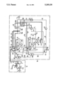
- the drawing is a schematic circuit diagram illustrating the way in which a partial loop according to the invention is disposed in and incorporated into a water-steam loop of a steam turbine of a gas and steam turbine plant.
- gas and steam turbine plant which includes a gas turbine plant 1a and a steam turbine plant 1b.
- the gas turbine plant 1a includes a gas turbine 2 with an air compressor 3 coupled thereto, a generator 4 and a combustion chamber 5 which is upstream of the gas turbine 2 and is connected to a fresh air line 6 of the air compressor 3.
- the steam turbine plant 1b includes a steam turbine 10 with a generator 11 coupled thereto and a water-steam loop 12 having a condenser 13 downstream of the steam turbine 10, a feedwater tank 14 downstream of the condenser 13, and a steam generator 15.
- an exhaust gas line 9 is connected to an inlet 15a of the steam generator 15.
- the exhaust gas a leaves the steam generator 15 through an outlet 15b thereof in the direction of a non-illustrated chimney.
- the steam generator 15 includes a condensate preheater or preheating surfaces 20, a low-pressure heater 21, first and second series-connected preheaters 22 and 23, a high-pressure heater 24, and an intermediate superheater 25.
- the condensate preheater 20 has an inlet side which is connected to the condenser 13 over a line 30 that incorporates a condensate pump 31, and an outlet side which is connected to the feedwater tank 14 over a line 32.
- the first preheater 22 has an inlet side which is connected over a line 33, that incorporates a valve 34, to a high-pressure pump 35, that communicates with the feedwater tank 14.
- the second preheater 23 which is downstream of the first preheater 22, has an outlet side that is connected over a first branch 36 to a water-steam tank 37 of the high-pressure heater 24.
- the second preheater 23 is also connected over a second branch 38, which incorporates a corner valve 39, to a water-steam separating vessel 40.
- the high-pressure heater 24 includes an evaporator 45, which is connected to the water-steam tank 37 through a circulation line 46. A pump 47 is incorporated into the circulation line 46.
- the high-pressure heater 24 also includes a superheater 48, which has an inlet side that is connected to the water-steam tank 37 and an outlet side that is connected over a fresh steam line 49 to a high-pressure part 10a of the steam turbine 10.
- the high-pressure part 10a of the steam turbine 10 has an outlet side which is connected over a steam line 50 to both the intermediate superheater 25 and the water-steam separating vessel 40.
- the intermediate superheater 25 has an outlet side which is connected to a medium-pressure part 10b of the steam turbine 10 over a steam line 51.
- the medium-pressure part 10b is followed by a low-pressure part 10c of the steam turbine 10.
- the turbine parts 10a, 10b and 10c of the steam turbine 10 drive the generator 11 with a common shaft 52.
- the low-pressure heater 21 includes an evaporator 60, which is connected over a circulation line 61 having a pump 62, to a water-steam tank 63.
- the low-pressure heater 21 also includes a superheater 64, which has an inlet side that is connected over a steam line 65 to both the water-steam tank 63 and a water-steam separating vessel 86.
- the superheater 64 has an outlet side that is connected over a steam line 67 to the low-pressure part 10c of the steam turbine 10.
- the water-steam tank 63 is connected over a line 66 to the feedwater tank 14.
- a low-pressure pump 68 is incorporated into the line 66.
- the water-steam loop 12 of the steam turbine 10 includes a partial loop 70, extending outside the steam generator 15.
- the preheater 22 disposed in the steam generator 15 is connected parallel to this partial loop.
- the partial loop 70 has an inlet side which is connected to the feedwater tank 14 through the high-pressure pump 35 and an outlet side which is connected to the preheater 22, in a region between the preheaters 22 and 23.
- a heat exchanger 71 is incorporated into the partial loop 70.
- the heat exchanger 71 has a primary side which communicates with the low-pressure part 10c of the steam turbine 10 over a steam line 72 and with the feedwater tank 14 over a water line 73.
- a regulating valve 74 to which a control signal s can be supplied over a signal line 75, is incorporated into the partial loop 70.
- the combustion chamber 5 is supplied with coal k through a supply line 7, in a manner which is not shown in further detail.
- the coal k is burned in the combustion chamber 5 with condensed fresh air 1 from the air compressor 3.
- Hot flue gas g produced in the combustion is carried over a flue gas line 8 into the gas turbine 2, where it expands and in so doing drives the gas turbine 2, which in turn drives the air compressor 3 and the generator 4.
- the hot exhaust gases a emerging from the gas turbine are introduced over the hot exhaust gas line 9 into the steam generator 15, where they are used to generate steam for the steam turbine.
- the steam emerging from the low-pressure part 10c of the steam turbine 10 is delivered over a steam line 80 to the condenser 13 and condenses there.
- the condensate is pumped into the condensate preheater 20 and heated there.
- the heated condensate flows out of the condensate preheater 20 into the feedwater tank 14 over the line 32.
- the feedwater from the feedwater tank 14 is pumped by the pump 35 into both the preheater 22 and the partial loop 70.
- a partial quantity t 2 that flows through the preheater 22 is adjustable with the valve 34.
- a partial or throughput quantity t 1 of the feedwater that flows through the partial loop 70 is set with the regulating valve 74 and is admixed with the feedwater preheated in the preheater 22.
- the partial quantity t 1 of the feedwater flowing in the partial loop 70 is preheated by indirect heat exchange with steam from the low-pressure part 10c of the steam turbine 10, to a temperature that corresponds to a partial quantity t 2 of the feedwater preheated in the preheater 22.
- the preheated feedwater flows through the second preheater 23 and is carried through the line 36 into the water-steam tank 37 of the high-pressure heater 24. From there, the preheated feedwater collected in the water-steam tank 37 flows through the evaporator 45, which has been heated by the hot exhaust gas a, and is evaporated as a result.
- the steam separated in the water-steam tank 37 flows through the superheater 48, which is heated by the exhaust gas a. In the superheated state, at a pressure of approximately 110 bar, this steam is delivered through the fresh steam line 49 to the high-pressure part 10a of the steam turbine part 10.
- the steam which is expanded in the high-pressure part 10a, flows at a pressure of approximately 30 bar through the intermediate superheater 25 and is then relieved or expanded to a pressure of approximately 3 bar in the medium-pressure part 10b of the steam turbine 10.
- Some of the steam expanded in the high-pressure part 10a flows as so-called wet steam through the steam line 50 into the water-steam separating vessel 40.
- the steam which is still at a pressure of approximately 30 bar, is separated from the water.
- the water can be introduced into the water-steam separating vessel 86 over a line 81 in which a valve 82 is incorporated.
- the pressure in the water-steam separating vessel 86 is approximately 3 bar, so that the water flowing in through the line 81 evaporates immediately.
- the water that is separated out in the water-steam separating vessel 86 is delivered to the feedwater tank 14 over a line 83.
- the steam that is separated out in the water-steam separating vessel 86 is delivered to the low-pressure heater 21.
- Another partial quantity t 3 of the feedwater is pumped out of the feedwater tank 14 by the low-pressure pump 68 into the water-steam tank 63 of the low-pressure heater 21. There, the feedwater is pumped by the pump 62 through the evaporator 60 and back again into the water-steam tank 63.
- the steam that is produced in the process is superheated, along with the steam emerging from the water-steam separating vessel 86, in the superheater 64, and is carried through the steam line 67 to the low-pressure part 10c of the steam turbine 10. There, the steam together with the steam flowing out of the medium-pressure part 10b is expanded and delivered to the condenser 13 through the steam line 80.
- a heat reservoir is created in the region of the preheater 22 in the steam generator 15, which is constructed either as a steam generator with supplementary firing, in a manner which is not shown in detail herein, or as a purely waste-heat boiler, as is shown in the exemplary embodiment.
- This heat reservoir is advantageously used to produce steam for the low-pressure part 10c of the steam turbine 10.
- the heat reservoir may also be used, for instance, to produce steam for the medium-pressure part 10b of the steam turbine 10 or as an additional preheating stage.
- the partial quantity t 2 of feedwater flowing through the preheater 22 disposed in the steam generator 15 is adjusted to the available water quantity in partial-load operation, so that the additionally available partial quantity t 1 in full-load operation is carried through the partial loop 70.
- the partial or throughput quantity t 1 of the partial loop 70 is adjusted in such a way that in all of the operating states, the partial quantity t 2 flowing through the preheater 22 is approximately constant.
- the throughput quantity t 1 flowing in the partial loop 70 is therefore suitably set as a function of the available total water quantity.
- a further suitable controlled variable is the quantity of heat introduced into the steam generator 15 with the exhaust gases a, and optionally with the flue gases additionally produced in the case of a steam generator with supplementary firing.
- the signal s corresponding to these controlled variables is supplied to the regulating valve 74 over the control line 75, in a manner which is not shown in detail.
- the partial or throughput quantity t 1 in the partial loop 70 amounts to approximately 30 to 50%, and preferably 40%, of the total water quantity.
- the supplementary firing is reduced first. It is only then, as a further provision, that the output of the gas turbine 2 is lowered. If a purely waste-heat boiler is used as the steam generator 15, then if the load decreases, the output of the gas turbine 2 is decreased immediately. In both cases, the quantity of heat introduced into the steam generator 15 drops, so that the total available quantity of feedwater decreases because of the reduced steam production.
- the partial loop 70 With the incorporation of the partial loop 70 according to the invention, it is possible for the partial quantity t 2 flowing through the preheater 22 in the steam generator 15 to remain constant over a wide load range, or in other words in both full-load and partial-load operation, even though the total feedwater quantity has decreased.
- the regulating valve 74 With decreasing load, the regulating valve 74 is continuously closed.
- the quantity of steam supplied to the primary side of the heat exchanger 71 is reduced down to zero in the partial-load range. This provision has the effect of causing the low-pressure heater 21 to produce steam continuously, so that over the entire load range, the temperature of the exhaust gases a downstream of the evaporator 60 remains approximately constant.
- the overall advantage of this is that both with a steam generator 15 with supplementary firing and with a steam generator 15 constructed as a waste-heat boiler, in all of the operating states of the plant, optimal utilization of the quantity of heat introduced into the steam generator 15, with a simultaneously low temperature of the exhaust gases a leaving the steam generator 15, is possible.
Landscapes
- Engineering & Computer Science (AREA)
- Chemical & Material Sciences (AREA)
- Combustion & Propulsion (AREA)
- Mechanical Engineering (AREA)
- General Engineering & Computer Science (AREA)
- Engine Equipment That Uses Special Cycles (AREA)
Applications Claiming Priority (2)
| Application Number | Priority Date | Filing Date | Title |
|---|---|---|---|
| DE4117313 | 1991-05-27 | ||
| DE4117313 | 1991-05-27 |
Publications (1)
| Publication Number | Publication Date |
|---|---|
| US5269130A true US5269130A (en) | 1993-12-14 |
Family
ID=6432546
Family Applications (1)
| Application Number | Title | Priority Date | Filing Date |
|---|---|---|---|
| US07/889,506 Expired - Fee Related US5269130A (en) | 1991-05-27 | 1992-05-27 | Method for operating a gas and steam turbine plant and gas and steam turbine plant operated according to the method |
Country Status (4)
| Country | Link |
|---|---|
| US (1) | US5269130A (de) |
| EP (1) | EP0515911B1 (de) |
| DE (1) | DE59205640D1 (de) |
| RU (1) | RU2062332C1 (de) |
Cited By (15)
| Publication number | Priority date | Publication date | Assignee | Title |
|---|---|---|---|---|
| US5365730A (en) * | 1990-09-21 | 1994-11-22 | Siemens Aktiengesellschaft | Combined gas and steam turbine system |
| US5992138A (en) * | 1995-07-27 | 1999-11-30 | Siemens Aktiengesellschaft | Method for operating a gas and steam-turbine plant and plant working according to the method |
| US6230480B1 (en) | 1998-08-31 | 2001-05-15 | Rollins, Iii William Scott | High power density combined cycle power plant |
| US6467273B1 (en) | 2001-03-01 | 2002-10-22 | Henry A. Lott | Method for producing electrical power |
| US20040025503A1 (en) * | 2002-08-09 | 2004-02-12 | Youichi Hattori | Combined cycle plant |
| US20040138472A1 (en) * | 2001-08-30 | 2004-07-15 | Marioara Mendelovici | Novel sulfonation method for zonisamide intermediate in zonisamide synthesis and their novel crystal forms |
| US6968700B2 (en) | 2001-03-01 | 2005-11-29 | Lott Henry A | Power systems |
| US20070130952A1 (en) * | 2005-12-08 | 2007-06-14 | Siemens Power Generation, Inc. | Exhaust heat augmentation in a combined cycle power plant |
| US20110210555A1 (en) * | 2010-02-26 | 2011-09-01 | Xia Jian Y | Gas turbine driven electric power system with constant output through a full range of ambient conditions |
| US20110277469A1 (en) * | 2008-09-17 | 2011-11-17 | Avraham Brenmiller | Solar thermal power plant |
| US20120234263A1 (en) * | 2011-03-18 | 2012-09-20 | Uop Llc | Processes and systems for generating steam from multiple hot process streams |
| US20120240549A1 (en) * | 2011-03-24 | 2012-09-27 | General Electric Company | Combined Cycle Power Plant |
| US20170145850A1 (en) * | 2015-11-19 | 2017-05-25 | Borgwarner Inc. | Waste heat recovery system for a power source |
| US20180216497A1 (en) * | 2017-01-31 | 2018-08-02 | General Electric Company | Steam turbine preheating system |
| US10337357B2 (en) | 2017-01-31 | 2019-07-02 | General Electric Company | Steam turbine preheating system with a steam generator |
Families Citing this family (6)
| Publication number | Priority date | Publication date | Assignee | Title |
|---|---|---|---|---|
| DE19539756C2 (de) * | 1995-07-27 | 1999-09-02 | Soon | Ad-/Desorptionskühlverfahren zur Kraftwerksleistungssteigerung |
| WO1997007323A1 (de) * | 1995-08-18 | 1997-02-27 | Siemens Aktiengesellschaft | Gas- und dampfturbinenanlage und verfahren zum betreiben einer derartigen anlage sowie abhitzedampferzeuger für eine gas- und dampfturbinenanlage |
| DE19536839A1 (de) * | 1995-10-02 | 1997-04-30 | Abb Management Ag | Verfahren zum Betrieb einer Kraftwerksanlage |
| DE19645322B4 (de) * | 1996-11-04 | 2010-05-06 | Alstom | Kombinierte Kraftwerksanlage mit einem Zwangsdurchlaufdampferzeuger als Gasturbinen-Kühlluftkühler |
| DE19736889C1 (de) * | 1997-08-25 | 1999-02-11 | Siemens Ag | Verfahren zum Betreiben einer Gas- und Dampfturbinenanlage und Gas- und Dampfturbinenanlage zur Durchführung des Verfahrens |
| RU2160370C2 (ru) * | 1999-03-19 | 2000-12-10 | Акционерное общество открытого типа "Всероссийский теплотехнический научно-исследовательский институт" | Высокоэкономичная парогазовая установка малой мощности |
Citations (8)
| Publication number | Priority date | Publication date | Assignee | Title |
|---|---|---|---|---|
| US3331202A (en) * | 1965-02-15 | 1967-07-18 | Sulzer Ag | Steam power plant |
| US3992876A (en) * | 1974-01-15 | 1976-11-23 | Sulzer Brothers Limited | Combined gas turbine and steam power plant |
| US4250704A (en) * | 1978-08-16 | 1981-02-17 | Kraftwerk Union Aktiengesellschaft | Combined gas-steam power plant with a fuel gasification device |
| US4253300A (en) * | 1979-08-03 | 1981-03-03 | General Electric Company | Supplementary fired combined cycle power plants |
| US4288979A (en) * | 1979-09-21 | 1981-09-15 | Combustion Engineering, Inc. | Combined cycle power plant incorporating coal gasification |
| US4465027A (en) * | 1982-03-31 | 1984-08-14 | Sulzer Brothers Limited | Exhaust gas vapor generator |
| US4841722A (en) * | 1983-08-26 | 1989-06-27 | General Electric Company | Dual fuel, pressure combined cycle |
| US5069685A (en) * | 1990-08-03 | 1991-12-03 | The United States Of America As Represented By The United States Department Of Energy | Two-stage coal gasification and desulfurization apparatus |
Family Cites Families (3)
| Publication number | Priority date | Publication date | Assignee | Title |
|---|---|---|---|---|
| DE1426443B2 (de) * | 1962-09-21 | 1971-09-09 | Waermekraftanlage | |
| FR2043957A5 (de) * | 1969-05-14 | 1971-02-19 | Stein Industrie | |
| EP0410111B1 (de) * | 1989-07-27 | 1993-01-20 | Siemens Aktiengesellschaft | Abhitzedampferzeuger für ein Gas- und Dampfturbinenkraftwerk |
-
1992
- 1992-05-13 DE DE59205640T patent/DE59205640D1/de not_active Expired - Fee Related
- 1992-05-13 EP EP92108102A patent/EP0515911B1/de not_active Expired - Lifetime
- 1992-05-15 RU SU925011533A patent/RU2062332C1/ru active
- 1992-05-27 US US07/889,506 patent/US5269130A/en not_active Expired - Fee Related
Patent Citations (8)
| Publication number | Priority date | Publication date | Assignee | Title |
|---|---|---|---|---|
| US3331202A (en) * | 1965-02-15 | 1967-07-18 | Sulzer Ag | Steam power plant |
| US3992876A (en) * | 1974-01-15 | 1976-11-23 | Sulzer Brothers Limited | Combined gas turbine and steam power plant |
| US4250704A (en) * | 1978-08-16 | 1981-02-17 | Kraftwerk Union Aktiengesellschaft | Combined gas-steam power plant with a fuel gasification device |
| US4253300A (en) * | 1979-08-03 | 1981-03-03 | General Electric Company | Supplementary fired combined cycle power plants |
| US4288979A (en) * | 1979-09-21 | 1981-09-15 | Combustion Engineering, Inc. | Combined cycle power plant incorporating coal gasification |
| US4465027A (en) * | 1982-03-31 | 1984-08-14 | Sulzer Brothers Limited | Exhaust gas vapor generator |
| US4841722A (en) * | 1983-08-26 | 1989-06-27 | General Electric Company | Dual fuel, pressure combined cycle |
| US5069685A (en) * | 1990-08-03 | 1991-12-03 | The United States Of America As Represented By The United States Department Of Energy | Two-stage coal gasification and desulfurization apparatus |
Cited By (29)
| Publication number | Priority date | Publication date | Assignee | Title |
|---|---|---|---|---|
| US5365730A (en) * | 1990-09-21 | 1994-11-22 | Siemens Aktiengesellschaft | Combined gas and steam turbine system |
| US5992138A (en) * | 1995-07-27 | 1999-11-30 | Siemens Aktiengesellschaft | Method for operating a gas and steam-turbine plant and plant working according to the method |
| US7131259B2 (en) | 1998-08-31 | 2006-11-07 | Rollins Iii William S | High density combined cycle power plant process |
| US20070204623A1 (en) * | 1998-08-31 | 2007-09-06 | William Rollins | High density combined cycle power plant process |
| US6494045B2 (en) | 1998-08-31 | 2002-12-17 | Rollins, Iii William S. | High density combined cycle power plant process |
| US6606848B1 (en) | 1998-08-31 | 2003-08-19 | Rollins, Iii William S. | High power density combined cycle power plant system |
| US6230480B1 (en) | 1998-08-31 | 2001-05-15 | Rollins, Iii William Scott | High power density combined cycle power plant |
| US20040031256A1 (en) * | 1998-08-31 | 2004-02-19 | Rollins William S. | High power density combined cycle power plant system and method |
| US6792759B2 (en) | 1998-08-31 | 2004-09-21 | William S. Rollins | High density combined cycle power plant process |
| US20050150230A1 (en) * | 1998-08-31 | 2005-07-14 | Rollins William S.Iii | High density combined cycle power plant process |
| US6467273B1 (en) | 2001-03-01 | 2002-10-22 | Henry A. Lott | Method for producing electrical power |
| US6968700B2 (en) | 2001-03-01 | 2005-11-29 | Lott Henry A | Power systems |
| US20040138472A1 (en) * | 2001-08-30 | 2004-07-15 | Marioara Mendelovici | Novel sulfonation method for zonisamide intermediate in zonisamide synthesis and their novel crystal forms |
| US20050198939A1 (en) * | 2002-08-09 | 2005-09-15 | Youichi Hattori | Combined cycle plant |
| US6983585B2 (en) * | 2002-08-09 | 2006-01-10 | Hitachi, Ltd. | Combined cycle plant |
| US7367192B2 (en) | 2002-08-09 | 2008-05-06 | Hitachi, Ltd. | Combined cycle plant |
| US20040025503A1 (en) * | 2002-08-09 | 2004-02-12 | Youichi Hattori | Combined cycle plant |
| US20070130952A1 (en) * | 2005-12-08 | 2007-06-14 | Siemens Power Generation, Inc. | Exhaust heat augmentation in a combined cycle power plant |
| US8544273B2 (en) * | 2008-09-17 | 2013-10-01 | Siemens Concentrated Solar Power Ltd. | Solar thermal power plant |
| US20110277469A1 (en) * | 2008-09-17 | 2011-11-17 | Avraham Brenmiller | Solar thermal power plant |
| US20110210555A1 (en) * | 2010-02-26 | 2011-09-01 | Xia Jian Y | Gas turbine driven electric power system with constant output through a full range of ambient conditions |
| US20120234263A1 (en) * | 2011-03-18 | 2012-09-20 | Uop Llc | Processes and systems for generating steam from multiple hot process streams |
| US20120240549A1 (en) * | 2011-03-24 | 2012-09-27 | General Electric Company | Combined Cycle Power Plant |
| US9404393B2 (en) * | 2011-03-24 | 2016-08-02 | General Electric Company | Combined cycle power plant |
| US20170145850A1 (en) * | 2015-11-19 | 2017-05-25 | Borgwarner Inc. | Waste heat recovery system for a power source |
| US9863266B2 (en) * | 2015-11-19 | 2018-01-09 | Borgwarner Inc. | Waste heat recovery system for a power source |
| US20180216497A1 (en) * | 2017-01-31 | 2018-08-02 | General Electric Company | Steam turbine preheating system |
| US10174639B2 (en) * | 2017-01-31 | 2019-01-08 | General Electric Company | Steam turbine preheating system |
| US10337357B2 (en) | 2017-01-31 | 2019-07-02 | General Electric Company | Steam turbine preheating system with a steam generator |
Also Published As
| Publication number | Publication date |
|---|---|
| RU2062332C1 (ru) | 1996-06-20 |
| DE59205640D1 (de) | 1996-04-18 |
| EP0515911A1 (de) | 1992-12-02 |
| EP0515911B1 (de) | 1996-03-13 |
Similar Documents
| Publication | Publication Date | Title |
|---|---|---|
| US5345755A (en) | Steam turbine plant | |
| JP3032005B2 (ja) | ガス・蒸気タービン複合設備 | |
| KR100385372B1 (ko) | 가스및증기터빈플랜트의운전방법및이에따라동작하는플랜트 | |
| US5442908A (en) | Combined combustion and steam turbine power plant | |
| US5293842A (en) | Method for operating a system for steam generation, and steam generator system | |
| EP0290220B1 (de) | Wärmewiedergewinnungskessel vom Zwischenüberhitzertyp und diesen verwendende Krafterzeugungsanlage | |
| US6393822B2 (en) | Cooling steam supply method of a combined cycle power generation plant | |
| US4572110A (en) | Combined heat recovery and emission control system | |
| RU2062332C1 (ru) | Комбинированная газопаротурбинная устанвока | |
| JP3783195B2 (ja) | ガスタービン及び蒸気タービンを有する複合発電所における電流発生 | |
| US5285627A (en) | Method for operating a gas and steam turbine plant and a plant for performing the method | |
| US6497101B2 (en) | Method and apparatus for regulating the steam temperature of the live steam or reheater steam in a combined-cycle power plant | |
| US4637212A (en) | Combined hot air turbine and steam power plant | |
| JPH0642703A (ja) | ガスタービンと組合せたセメント廃熱回収発電設備 | |
| US6062017A (en) | Steam generator | |
| US5367870A (en) | Gas and steam turbine system | |
| JPH11509901A (ja) | ガス・蒸気複合タービン設備の運転方法並びにこの方法で作動する設備 | |
| US3913330A (en) | Vapor generator heat recovery system | |
| EP0639254B1 (de) | Methode anwendbar bei kleinen kraftanlagen | |
| RU2801652C1 (ru) | Способ работы парогазовой установки электростанции | |
| RU2794404C1 (ru) | Парогазовая установка электростанции | |
| RU2067667C1 (ru) | Способ работы парогазовой установки | |
| JPH01280604A (ja) | 蒸気プロセスの効率を高める方法 | |
| JPS59147907A (ja) | 蒸気タ−ビンプラントの給水加熱系統 | |
| JP2000205556A (ja) | 貫流ボイラ装置の運転方法 |
Legal Events
| Date | Code | Title | Description |
|---|---|---|---|
| AS | Assignment |
Owner name: SIEMENS AKTIENGESELLSCHAFT, GERMANY Free format text: ASSIGNMENT OF ASSIGNORS INTEREST;ASSIGNORS:FINCKH, HERMANN;BRUECKNER, HERMANN;REEL/FRAME:006690/0814;SIGNING DATES FROM 19920515 TO 19920602 |
|
| REMI | Maintenance fee reminder mailed | ||
| LAPS | Lapse for failure to pay maintenance fees | ||
| FP | Lapsed due to failure to pay maintenance fee |
Effective date: 19971217 |
|
| STCH | Information on status: patent discontinuation |
Free format text: PATENT EXPIRED DUE TO NONPAYMENT OF MAINTENANCE FEES UNDER 37 CFR 1.362 |