US5249286A - Selectively locking memory locations within a microprocessor's on-chip cache - Google Patents
Selectively locking memory locations within a microprocessor's on-chip cache Download PDFInfo
- Publication number
- US5249286A US5249286A US07/982,031 US98203192A US5249286A US 5249286 A US5249286 A US 5249286A US 98203192 A US98203192 A US 98203192A US 5249286 A US5249286 A US 5249286A
- Authority
- US
- United States
- Prior art keywords
- instruction
- data
- microprocessor
- cache
- entries
- Prior art date
- Legal status (The legal status is an assumption and is not a legal conclusion. Google has not performed a legal analysis and makes no representation as to the accuracy of the status listed.)
- Expired - Lifetime
Links
Images


Classifications
-
- G—PHYSICS
- G06—COMPUTING OR CALCULATING; COUNTING
- G06F—ELECTRIC DIGITAL DATA PROCESSING
- G06F12/00—Accessing, addressing or allocating within memory systems or architectures
- G06F12/02—Addressing or allocation; Relocation
- G06F12/08—Addressing or allocation; Relocation in hierarchically structured memory systems, e.g. virtual memory systems
- G06F12/12—Replacement control
- G06F12/121—Replacement control using replacement algorithms
- G06F12/126—Replacement control using replacement algorithms with special data handling, e.g. priority of data or instructions, handling errors or pinning
Definitions
- the present invention relates to microprocessor architectures and, in particular, to a method and apparatus for locking individual selected entries in integrated cache memory.
- the central processing unit processes instructions and operands which it retrieves from main memory via an external interface bus. Because the central processing unit can execute its functions at a rate much faster than the rate at which the instructions and operands can be retrieved from external main memory, a small high-speed cache memory is often located on-chip between the central processing unit and main memory to minimize the time spent by the central processing unit waiting for instructions and data.
- a cache memory is typically organized as a number of blocks of data or instruction information. Each cache block has an associated address tag that uniquely identifies the corresponding block of main memory of which it is a copy. Each time the central processing unit makes an external memory reference, an address tag comparison is made to determine whether the requested data or referenced instruction is stored in the integrated cache. If it is stored in the cache (a "hit”), then the information is provided to the processor from the cache. If it is not stored in the cache (a "miss”), then the information is retrieved from main memory for use by the processor and to replace a block presently stored in the cache in accordance with a replacement algorithm.
- the cache while located in the microprocessor's computing cluster, was not integrated on the same semiconductor "microchip” with the central processing unit.
- Presently available microprocessors utilize a cache memory which is integrated "on-chip” to provide the advantage of further reducing the time delay inherent in going "off-chip” for information.
- Integrated cache is essential for achieving top microprocessor performance.
- the on-chip cache of the NS32532 device includes a 512-byte instruction cache and a separate 1024-byte data cache.
- the instruction cache of the NS32532 microprocessor stores 512-bytes in a direct-map organization. That is, five-bits of a reference instruction's virtual address select 1 of 32 instruction cache sets. Each set contains 16-bytes of code and a log that holds address tags comprising the 23 most-significant bits of the physical address for the locations stored in that set.
- the instruction cache of the NS32532 device also includes a 16-byte instruction buffer from which it can transfer 32-bits of code per cycle to the loader of the microprocessor's instruction pipeline. If the reference instruction is found in the instruction cache, then the instruction buffer is loaded directly from the selected instruction cache set. If the reference instruction is not found in the instruction cache, then the instruction cache transfers the virtual address of the reference to the memory management unit which translates the virtual address to a corresponding physical address for a bus interface unit. The bus interface unit then initiates a read cycle to load the reference instruction from main memory via the external bus. The pipeline's instruction buffer is then written to one of the sets of the instruction cache in accordance with the replacement algorithm.
- the data cache of the NS32532 device stores 1024-bytes of data in a two-way set associative organization. That is, each set of the data cache includes two entries containing 16-bytes and two address tags that hold the 23 most-significant bits of the physical address for locations stored in the two entries. Five-bits of the virtual address of the reference are used to select the appropriate set within the data cache from which to read the two entries. Simultaneously, the integrated memory management unit of the NS32532 device is translating the virtual address and transferring the resultant physical address to the data cache and to the bus interface unit. The data cache compares the two address tags with the physical address while the bus interface unit initiates an external bus cycle to read the data from main memory.
- the cache reference is a hit, then the selected data is aligned by the data cache and transferred to the execution unit while the bus interface unit cancels the external bus cycle. If the cache reference is a miss, then the bus interface unit completes the external bus cycle and transfers data from main memory to the execution unit and to the data cache, which updates its cache entry in accordance with its replacement algorithm.
- Both the instruction cache and the data cache of the NS32532 microprocessor support an operating mode to lock their contents. This feature can be used in real-time systems to allow faster on-chip access to the most critical subroutines and data.
- the NS32532 microprocessor requires locking of the entire cache contents. In many applications, however, only a portion of the cache is required to store time-critical code and data. Consequently, it is inefficient to require that the entire cache be locked.
- the present invention provides a microprocessor architecture that includes capabilities for locking individual entries of its integrated instruction cache and data cache while leaving the remainder of the cache unlocked and available for use in capturing the microprocessor's dynamic locality of reference.
- the microprocessor also includes the capability for locking instruction cache entries without requiring that the instructions be executed during the locking process.
- FIG. 1 is a block diagram illustrating a microprocessor architecture that incorporates the concepts of the present invention.
- FIG. 2 is a block diagram illustrating the structure of a data utilizable in the FIG. 1 architecture.
- FIG. 3 is a block diagram illustrating the structure of an instruction cache utilizable in the FIG. 1 architecture.
- FIG. 1 shows the architecture of a microprocessor 10 that includes multiple, pipelined functional units capable of executing two instructions in parallel.
- the microprocessor 10 includes three main sections: an instruction processor 12, an execution processor 14 and a bus interface processor 16.
- the instruction processor 12 includes three modules: an instruction loader 18, an instruction emulator 20 and an instruction cache 22. These modules load instructions from the external system through the bus interface processor 16, store the instructions in the instruction cache 22 and provide pairs of instructions to the execution processor 14 for execution.
- the execution processor 14 includes two 4-stage pipelined integer execution units 24 and 26, a double-precision 5-stage pipelined floating point execution unit 28, and a 1024 byte data cache 30.
- a set of integer registers 32 services the two integer units 24 and 26; similarly, a set of floating point registers 34 services the floating point execution unit 28.
- the bus interface processor 16 includes a bus interface unit 36 and a number of system modules 38.
- the bus interface unit 36 controls the bus accesses requested by both the instruction processor 12 and the execution processor 14.
- the system modules 38 include a timer 40, a direct memory access (DMA) controller 42, an interrupt control unit (ICU) 44 and I/O buffers 46.
- DMA direct memory access
- ICU interrupt control unit
- the instruction loader 18 partially decodes instructions retrieved from main memory and places the partially decoded instructions in the instruction cache 22. That is, the instruction loader 18 translates an instruction stored in main memory (not shown) into the partially decoded format of the instruction cache 22.
- the instruction loader 18 is also responsible for checking whether any dependencies exist between consecutive instructions that are paired in a single instruction cache entry.
- the instruction cache 22 contains 512 entries for partially decoded instructions.
- Each entry in the instruction cache 22 contains either one or two instructions stored in a partially decoded format for efficient control of the various functional units of the microprocessor 10.
- Each entry in instruction cache 22 also contains auxiliary information that indicates whether the two instructions stored in that entry are independent, so that they can be executed in parallel, or dependent, so that they must be executed sequentially
- the instruction emulator 20 executes special instructions defined in the instruction set of the microprocessor 10. When the instruction loader 18 encounters such an instruction, it transfers control to the emulator 20.
- the emulator is responsible for generating a sequence of core instructions that perform the function of a single complex instruction. In this regard, the emulator 20 provides ROM-resident microcode.
- the emulator 20 also controls exception processing and self-test operations.
- the two 4-stage integer pipelines 24 and 26 perform basic arithmetic/logical operations and data memory references.
- Each integer pipeline 24,26 can execute instructions at a throughput of one instruction per system clock cycle.
- the floating point execution unit 28 includes three sub-units that perform single-precision and double-precision operations.
- An FPU adder sub-unit 28a is responsible for add and convert operations
- a second sub-unit 28b is responsible for multiply operations
- a third sub-unit 28c is responsible for divide operations.
- the floating point execution unit 28 can execute instructions at a throughput of one instruction per system clock cycle.
- Memory references for the floating point execution unit 28 are controlled by one of the integer pipelines 24,26 and can be performed in parallel to floating-point operations.
- Data memory references are performed using the 1-Kbyte data cache 30.
- the data cache 30 provides fast on-chip access to frequently used data.
- off-chip references are performed by the bus interface unit (BIU) 36 using the pipelined system bus 48.
- the data cache 30 employs a load scheduling technique so that it does not necessarily stall on misses. This means that the two execution pipelines 24,26 can continue processing instructions and initiating additional memory references while data is being read from main memory.
- the bus interface unit 36 can receive requests for main memory accesses from either the instruction processor 12 or the execution processor 14. These requests are sent to the external pipelined bus 48.
- the external bus can be programmed to operate at half the frequency of the microprocessor 10; this allows for a simple instruction interface at a relatively low frequency while the microprocessor 10 executes a pair of instructions at full rate.
- the instruction set of the microprocessor 10 is partitioned into a core part and a non-core part.
- the core part of the instruction set consists of performance critical instructions and addressing modes, together with some special-function instructions for essential system operations.
- the non-core part consists of the remainder of the instruction set.
- Performance critical instructions and addressing modes were selected based on an analysis and evaluation of the operating system (UNIX in this case) workload and various engineering, scientific and embedded controller applications. These instructions are executed directly as part of the RISC architecture of microprooessor 10.
- the microprocessor 10 includes seventy-five internal registers grouped in internal register file according to functions as follows: thirty-two general-purpose registers, thirty-two single-precision floating-point data registers, three dedicated address registers, one Processor Status Register (PSR), one Configuration Register (CFG), one Floating-Point Status Register (FSR), and six debug registers.
- the Configuration Register (CFG) is used to enable or disable various operating modes of the microprocessor 10, including the locking of selective entries in the Data Cache 28 and Instruction Cache 32.
- the format of the Configuration Register (CFG) is as follows:
- DC Data Cache Enable. This bit enables the Data Cache 30 to be accessed for data reads and writes.
- LDC Lock Data Cache. This bit controls whether a missing line that is placed in the Data Cache 30 will be locked into the cache. Locked lines are not subject to replacement from the Data Cache 30.
- IC Instruction Cache Enable. This bit enables the Instruction Cache 22 to be accessed for instruction fetches.
- LIC Lock Instruction Cache. This bit controls whether a missing instruction that is placed in the Instruction Cache 22 will be locked into the cache. Locked lines are not subject to replacement from the Instruction Cache 22.
- ISR Interrupt Service Registers. While this bit is 1, access to specific general-purpose registers is restricted and a trap occurs when an attempt is made to access these registers in user-mode.
- PS This field specifies the page size used for the PAGE mechanism of microprocessor 10.
- Configuration Register bits 0 through 9 are cleared to 0.
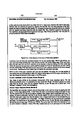
- FIG. 2 shows one possible embodiment of Data Cache 30.
- the 1-Kbyte Data Cache 30 utilizes a 2-way, set-associative organization with 64 lines.
- 2-way, set associative means that for each memory address there are two lines in the cache where the address can be placed. The two lines are collectively called a "set".
- Each line contains a 23-bit tag 32a, 32b which holds the most-significant bits of the address of the data stored in the line, along with four double-words of data, four validity bits, and a lock-bit. (There is one validity bit for each double-word of data.) For each set there is an additional bit that indicates which line has been more recently used for purposes of implementing least-recently-used (LRU) replacement.
- LRU least-recently-used
- the Data Cache 30 is enabled for a data read if all of the following are true: bit CFG.DC of the Configuration Register is 1; the reference is not to read the semaphore while executing an MBITI instruction; and the reference (See Appendix) is neither Interrupt-Acknowledge nor End-of-Interrupt bus cycle.
- the Data Cache 30 If the Data Cache 30 is disabled, then the data read bypasses the Data Cache 30 and the contents of the Data Cache 30 are unaffected; the data is read directly from external memory. The data is then aligned and used to execute the instruction.
- address bits 4-8 as shown in FIG. 2, of the data address are decoded by decoder 34, to select the set, either data memory 0 (36a) or data memory 1 (36b), where the data may be stored.
- the two lines of the selected set are read and both tags are compared by tag compare module 38 with the 23 most-significant bits of the data's physical address.
- tag compare module 38 As further shown in FIG. 2, either a double-word or quad-word is read from the cache, depending on the operand's length.
- bits 2 and 3 of the data's address select the double-word (64 bit) and the corresponding validity bit from each line of the selected set.
- the missing data is read from external memory. Either a double-word or quad-word is read depending on the length of the operand and the bus width. After being read from memory, the missing data is aligned and used to execute the instruction.
- the tag in the line did not match the data's address at the time the miss was detected, then the tag of the line selected for replacement is loaded with the 23 most significant bits of the data's address, the line becomes locked if bit CFG.LDC of the Configuration Register is 1, the double-word or quad-word read from the system bus is written to the Data Cache 30, the corresponding validity bits are set, and the remaining validity bits are cleared.
- the Data Cache 30 is enabled for a data write whenever bit CFG.DC of the Configuration Register is 1, including references for MBITI instructions. Address bits 4-8 of the data address are decoded to select the Data Cache 30 set where the data may be stored. The two lines of the selected set are read and both tags are compared with the 23 most-significant bits of the data's physical address. Either a double-word or quad-word can be written, word reference, bits 2 and 3 of the data's address select the double-word and the corresponding validity bit from each line of the selected set. For a quad-word reference, two double-words and their corresponding validity bits are accessed.
- the data is aligned and used to update the double-word(s) in the Data Cache 30. If one of the double-words for the quad-word reference is valid but the other is not, then only the valid double-word is updated. If the data is not located in the Data Cache 30, then its contents are unaffected. The data is always written through to external memory.
- the contents of the Data Cache 30 can be invalidated by either software or hardware.
- the Data Cache 30 is invalidated by software as follows: The entire Data Cache contents, including locked lines, are invalidated while bit CFG.DC of the Configuration Register is 0. The LRU selection bit for each Data Cache set is also initialized to 0 while bit CFG.DC is 0. The CINV instruction (See Appendix A) can be executed to invalidate the entire Data Cache contents of Data Cache 30. Executing CINV invalidates either the entire cache or only unlocked lines, according to the instruction's U-option.
- the Data Cache 30 is invalidated in hardware as follows: The entire Data Cache contents, including locked lines, are invalidated when the Invalidate Data Cache input (INVDC) (See Appendix A) is asserted while the Invalidate Block input (INVBLK) (See Appendix A) is high.
- INVDC Invalidate Data Cache input
- INVBLK Invalidate Block input
- the microprocessor 10 reads an address from the Address Bus and searches to determine whether a copy of the 16-byte block specified by the address is found in one line of the Data Cache 30. If the search is successful, then the line is invalidated regardless of whether it is locked. Invalidation of a single block can only be performed when the microprocessor 10 has relinquished its Address Bus in response to a Hold Request input (HOLD) (See Appendix A) or an extended bus retry.
- HOLD Hold Request input
- the address can be presented to the microprocessor 10 along with a request to invalidate the 16-byte block. For example, this technique is appropriate for a single-processor system with a low-rate of I/O transfers to memory.
- Systems that use an external cache memory can maintain coherence between the on-chip Data Cache 30 and the external cache by requiring that the contents of the Data Cache 30 are always a subset of the external cache.
- the system can then freely employ any technique to maintain coherence between the external cache and main memory.
- To enforce the requirement that the Data Cache 30 contains only lines that are also in the external cache it is necessary for external hardware to request that the microprocessor 10 invalidate a block whenever the status of that block changes in the external cache.
- an external Cache Control Unit can implement this requirement by invalidating one or more blocks (depending on the line size of the external cache) whenever a line in the external cache is replaced, invalidated, or updated.
- FIG. 3 shows the structure of the Instruction Cache 22.
- the Instruction Cache 22 utilizes a 2-way, set-associative organization with 512 entries for partially decoded instructions.
- 2-way, set associative means that for each memory address there are two entries in the Instruction Cache 2 where the instruction located at that address can be placed. The two entries are called a set.
- Each entry contains one or two partially-decoded instructions that are represented with fixed fields for opcode, source and destination register numbers, and immediate values.
- the entry also includes auxiliary information used to control the sequence of instruction execution, including a bit to indicate whether the entry contains two consecutive instructions that can be executed in parallel, another bit to indicate whether the entry is for a complex instruction that is emulated, and additional information representing the length of the instruction(s) in a form that allows fast calculation of the next instruction's address.
- a 24-bit tag 42a, 42b which holds PSR.U (See Appendix A) along with the 22 most-significant bits and bit 2 of the address of the instruction stored in the entry. (Note that address bit 10 of the instruction stored in the tag is only significant when operating with half the Instruction Cache 22).
- the tag corresponds to the instruction at the lower address.
- 2 bits 44a, 44b that indicate whether the entry is valid and whether it is locked. For each set there is an additional bit 46 that indicates which entry has been most recently used for purposes of Least-Recently-Used (LRU) replacement.
- LRU Least-Recently-Used
- the Instruction Cache 22 is enabled for an instruction fetch if bit CFG.IC of the Configuration Register is 1.
- Instruction Cache 22 If the Instruction Cache 22 is disabled, then the instruction fetch bypasses the Instruction Cache 22 and the contents of the Instruction Cache 22 are unaffected.
- the instruction is read directly from external memory, partially decoded by the Loader 18 to form an entry (which may contain two partially decoded instructions), and transferred to the execution pipelines.
- the address bits 3-10 of the instruction's address are decoded to select the set of lines where the instruction may be stored.
- the selected set of two entries is read and the associated tags 42a, 42b are compared with PSR.U along with the 22 most-significant bits and bit 2 of the instruction address. If one tag matches and the matching entry is valid, then the entry is transferred to the instruction pipelines for execution. Otherwise, the missing instruction is read directly from external memory and partially decoded.
- the referenced instruction is missing from the Instruction Cache 22 and at least one of the entries in the selected set is not locked, then the following actions are taken.
- One of the entries is selected for replacement. Otherwise, entries are unlocked, then the least recently used entry is selected for replacement.
- the missing instruction is then read directly from external memory and partially decoded by Loader 18 to form an entry (that may contain two partially decoded instructions) which is transferred to the instruction pipelines for execution.
- CIIN is not asserted (low) during the bus cycles to read the missing instruction, then the partially decoded instruction is also written into the Instruction Cache entry selected for replacement, the associated valid bit is set, and the entry is locked if bit CFG.LIC in the Configuration Register is 1. If CIIN is asserted (high) during the bus cycle to read the missing instruction, then the contents of the entry for replacement is unaffected.
- the microprocessor 10 After the microprocessor 10 has completed fetching a missing instruction from external memory, it continues prefetching sequential instructions. For subsequent sequential instruction fetches, the microprocessor 10 searches the Instruction Cache 22 to determine whether the instruction is located on-chip. If the search is successful or a non-sequential instruction fetch occurs, the microprocessor 10 ceases prefetching. Otherwise, the prefetched instructions are rapidly available to decode and execute. The microprocessor 10 initiates instruction prefetches only during bus cycles that would otherwise be idle because no off-chip data references are required.
- the tag corresponds to the address of the first instruction (the one at the lower address). If a non-sequential fetch is made to the second instruction, then that instruction will not be found in the paired entry. That instruction can, however, be located in another entry that has a tag corresponding to that instruction's address.
- the contents of the Instruction Cache 22 can be invalidated by software or hardware.
- the Instruction Cache 22 is invalidated by software as follows: The entire Instruction Cache contents, including locked entries, are invalidated while bit CFG.IC of the Configuration Register is 0. The LRU selection bit is also initialized to 0 while bit CFG.IC is 0. The CINV instruction can be executed to invalidate the entire Instruction Cache contents. Executing CINV invalidates either the entire cache or only unlocked lines according the instruction's Y-option.
- the entire Instruction Cache 22 is invalidated in hardware by asserting (low) the INVIC input signal.
Landscapes
- Engineering & Computer Science (AREA)
- Theoretical Computer Science (AREA)
- Physics & Mathematics (AREA)
- General Engineering & Computer Science (AREA)
- General Physics & Mathematics (AREA)
- Memory System Of A Hierarchy Structure (AREA)
Abstract
A microprocessor architecture that includes capabilities for locking individual entries into its integrated instruction cache and data cache while leaving the remainder of the cache unlocked and available for use in capturing the microprocessor's dynamic locality of reference. The microprocessor also includes the capability for locking instruction cache entries without requiring that the instructions be executed during the locking process.
Description
This is a continuation of co-pending application Ser. No. 529,866 filed on May 29, 1990, now abandoned.
This specification includes an Appendix A titled "Swordfish Microprocessor Architecture Specification, REvision 2.0, February 1990". Appendix A may be found at the end of the Detailed Description of the Invention section of this document. Appendix A is hereby incorporated by reference as an integral part of this patent specification.
1. Field of the Invention
The present invention relates to microprocessor architectures and, in particular, to a method and apparatus for locking individual selected entries in integrated cache memory.
2. Discussion of the Prior Art
In a conventional single-chip microprocessor architecture, the central processing unit processes instructions and operands which it retrieves from main memory via an external interface bus. Because the central processing unit can execute its functions at a rate much faster than the rate at which the instructions and operands can be retrieved from external main memory, a small high-speed cache memory is often located on-chip between the central processing unit and main memory to minimize the time spent by the central processing unit waiting for instructions and data.
A cache memory is typically organized as a number of blocks of data or instruction information. Each cache block has an associated address tag that uniquely identifies the corresponding block of main memory of which it is a copy. Each time the central processing unit makes an external memory reference, an address tag comparison is made to determine whether the requested data or referenced instruction is stored in the integrated cache. If it is stored in the cache (a "hit"), then the information is provided to the processor from the cache. If it is not stored in the cache (a "miss"), then the information is retrieved from main memory for use by the processor and to replace a block presently stored in the cache in accordance with a replacement algorithm.
Cache memories may be organized into groups of smaller associative memories called sets, each set containing a number of storage locations, referred to as the set size. Thus, for a cache size m, divided into L sets, there are s=m/L storage locations in each set. When an address in main memory is mapped into the cache, it can appear in any of the L sets. For a cache of a given size, searching of the cache sets in parallel for a "hit" can improve access time by a factor of L.
In earlier microprocessor architectures, the cache, while located in the microprocessor's computing cluster, was not integrated on the same semiconductor "microchip" with the central processing unit. Presently available microprocessors utilize a cache memory which is integrated "on-chip" to provide the advantage of further reducing the time delay inherent in going "off-chip" for information. Integrated cache is essential for achieving top microprocessor performance.
An advanced microprocessor architecture that incorporates "on-chip" cache memory is the National Semiconductor Corporation 32-bit NS32532 microprocessor. The on-chip cache of the NS32532 device includes a 512-byte instruction cache and a separate 1024-byte data cache.
The instruction cache of the NS32532 microprocessor stores 512-bytes in a direct-map organization. That is, five-bits of a reference instruction's virtual address select 1 of 32 instruction cache sets. Each set contains 16-bytes of code and a log that holds address tags comprising the 23 most-significant bits of the physical address for the locations stored in that set.
The instruction cache of the NS32532 device also includes a 16-byte instruction buffer from which it can transfer 32-bits of code per cycle to the loader of the microprocessor's instruction pipeline. If the reference instruction is found in the instruction cache, then the instruction buffer is loaded directly from the selected instruction cache set. If the reference instruction is not found in the instruction cache, then the instruction cache transfers the virtual address of the reference to the memory management unit which translates the virtual address to a corresponding physical address for a bus interface unit. The bus interface unit then initiates a read cycle to load the reference instruction from main memory via the external bus. The pipeline's instruction buffer is then written to one of the sets of the instruction cache in accordance with the replacement algorithm.
The data cache of the NS32532 device stores 1024-bytes of data in a two-way set associative organization. That is, each set of the data cache includes two entries containing 16-bytes and two address tags that hold the 23 most-significant bits of the physical address for locations stored in the two entries. Five-bits of the virtual address of the reference are used to select the appropriate set within the data cache from which to read the two entries. Simultaneously, the integrated memory management unit of the NS32532 device is translating the virtual address and transferring the resultant physical address to the data cache and to the bus interface unit. The data cache compares the two address tags with the physical address while the bus interface unit initiates an external bus cycle to read the data from main memory. If the cache reference is a hit, then the selected data is aligned by the data cache and transferred to the execution unit while the bus interface unit cancels the external bus cycle. If the cache reference is a miss, then the bus interface unit completes the external bus cycle and transfers data from main memory to the execution unit and to the data cache, which updates its cache entry in accordance with its replacement algorithm.
Both the instruction cache and the data cache of the NS32532 microprocessor support an operating mode to lock their contents. This feature can be used in real-time systems to allow faster on-chip access to the most critical subroutines and data.
While providing a highly desirable cache locking feature, the NS32532 microprocessor requires locking of the entire cache contents. In many applications, however, only a portion of the cache is required to store time-critical code and data. Consequently, it is inefficient to require that the entire cache be locked.
The present invention provides a microprocessor architecture that includes capabilities for locking individual entries of its integrated instruction cache and data cache while leaving the remainder of the cache unlocked and available for use in capturing the microprocessor's dynamic locality of reference. The microprocessor also includes the capability for locking instruction cache entries without requiring that the instructions be executed during the locking process.
Other features and advantages of the present invention will be appreciated by reference to the detailed description of the invention provided below, which should be considered in conjunction with the accompanying drawings.
FIG. 1 is a block diagram illustrating a microprocessor architecture that incorporates the concepts of the present invention.
FIG. 2 is a block diagram illustrating the structure of a data utilizable in the FIG. 1 architecture.
FIG. 3 is a block diagram illustrating the structure of an instruction cache utilizable in the FIG. 1 architecture.
FIG. 1 shows the architecture of a microprocessor 10 that includes multiple, pipelined functional units capable of executing two instructions in parallel.
The microprocessor 10 includes three main sections: an instruction processor 12, an execution processor 14 and a bus interface processor 16.
The instruction processor 12 includes three modules: an instruction loader 18, an instruction emulator 20 and an instruction cache 22. These modules load instructions from the external system through the bus interface processor 16, store the instructions in the instruction cache 22 and provide pairs of instructions to the execution processor 14 for execution.
The execution processor 14 includes two 4-stage pipelined integer execution units 24 and 26, a double-precision 5-stage pipelined floating point execution unit 28, and a 1024 byte data cache 30. A set of integer registers 32 services the two integer units 24 and 26; similarly, a set of floating point registers 34 services the floating point execution unit 28.
The bus interface processor 16 includes a bus interface unit 36 and a number of system modules 38. The bus interface unit 36 controls the bus accesses requested by both the instruction processor 12 and the execution processor 14. In the illustrated embodiment, the system modules 38 include a timer 40, a direct memory access (DMA) controller 42, an interrupt control unit (ICU) 44 and I/O buffers 46.
The instruction loader 18 partially decodes instructions retrieved from main memory and places the partially decoded instructions in the instruction cache 22. That is, the instruction loader 18 translates an instruction stored in main memory (not shown) into the partially decoded format of the instruction cache 22. The instruction loader 18 is also responsible for checking whether any dependencies exist between consecutive instructions that are paired in a single instruction cache entry.
The instruction cache 22 contains 512 entries for partially decoded instructions.
Each entry in the instruction cache 22 contains either one or two instructions stored in a partially decoded format for efficient control of the various functional units of the microprocessor 10.
Each entry in instruction cache 22 also contains auxiliary information that indicates whether the two instructions stored in that entry are independent, so that they can be executed in parallel, or dependent, so that they must be executed sequentially
Further information relating to the architecture of microprocessor 10 and its partially decoded instruction cache is provided in commonly-assigned and copending application Ser. No. 07/529,869, filed by Alpert et al. on the same date as this application and titled PARTIALLY DECODED INSTRUCTION CACHE; the just-referenced application Ser. No. 07/529,869, is hereby incorporated by reference to provide further background information regarding the present invention.
The instruction emulator 20 executes special instructions defined in the instruction set of the microprocessor 10. When the instruction loader 18 encounters such an instruction, it transfers control to the emulator 20. The emulator is responsible for generating a sequence of core instructions that perform the function of a single complex instruction. In this regard, the emulator 20 provides ROM-resident microcode. The emulator 20 also controls exception processing and self-test operations.
The two 4- stage integer pipelines 24 and 26 perform basic arithmetic/logical operations and data memory references. Each integer pipeline 24,26 can execute instructions at a throughput of one instruction per system clock cycle.
The floating point execution unit 28 includes three sub-units that perform single-precision and double-precision operations. An FPU adder sub-unit 28a is responsible for add and convert operations, a second sub-unit 28b is responsible for multiply operations and a third sub-unit 28c is responsible for divide operations.
When add and multiply operations are alternately executed, the floating point execution unit 28 can execute instructions at a throughput of one instruction per system clock cycle.
Memory references for the floating point execution unit 28 are controlled by one of the integer pipelines 24,26 and can be performed in parallel to floating-point operations.
Data memory references are performed using the 1-Kbyte data cache 30. The data cache 30 provides fast on-chip access to frequently used data. In the event that referenced data are not located in the data cache 30, then off-chip references are performed by the bus interface unit (BIU) 36 using the pipelined system bus 48.
The data cache 30 employs a load scheduling technique so that it does not necessarily stall on misses. This means that the two execution pipelines 24,26 can continue processing instructions and initiating additional memory references while data is being read from main memory.
The bus interface unit 36 can receive requests for main memory accesses from either the instruction processor 12 or the execution processor 14. These requests are sent to the external pipelined bus 48. The external bus can be programmed to operate at half the frequency of the microprocessor 10; this allows for a simple instruction interface at a relatively low frequency while the microprocessor 10 executes a pair of instructions at full rate.
The instruction set of the microprocessor 10 is partitioned into a core part and a non-core part. The core part of the instruction set consists of performance critical instructions and addressing modes, together with some special-function instructions for essential system operations. The non-core part consists of the remainder of the instruction set. Performance critical instructions and addressing modes were selected based on an analysis and evaluation of the operating system (UNIX in this case) workload and various engineering, scientific and embedded controller applications. These instructions are executed directly as part of the RISC architecture of microprooessor 10.
More detailed information regarding both architecture of the microprocessor 10 and its instruction set is provided in Appendix A at the end of this Detailed Description of the Invention.
Many systems, like laser-beam printers digital signal processors, can deliver high performance with relatively slow external memory by scheduling memory loads in advance of processing the information. Thus, in accordance with the present invention, and as described in greater detail below, selected individual entries of each of the Data Cache 30 and Instruction Cache 22 can be locked on-chip for fast access to critical locations in real-time applications.
These locking features are implemented through the Configuration Register (CFG) that is included in the internal register file of microprocessor 10.
The microprocessor 10 includes seventy-five internal registers grouped in internal register file according to functions as follows: thirty-two general-purpose registers, thirty-two single-precision floating-point data registers, three dedicated address registers, one Processor Status Register (PSR), one Configuration Register (CFG), one Floating-Point Status Register (FSR), and six debug registers. The Configuration Register (CFG) is used to enable or disable various operating modes of the microprocessor 10, including the locking of selective entries in the Data Cache 28 and Instruction Cache 32. The format of the Configuration Register (CFG) is as follows:
______________________________________
31       9     7     6    5     4    3    2    1   0
 Reserved
         PS      ISR    LIC   IC   LDC  DC   O   F
______________________________________
The various control bits of the Configuration Register (CFG) are described below:
F : Floating-Point Instruction Set. This bit enables the execution of floating point instructions.
DC : Data Cache Enable. This bit enables the Data Cache 30 to be accessed for data reads and writes.
LDC : Lock Data Cache. This bit controls whether a missing line that is placed in the Data Cache 30 will be locked into the cache. Locked lines are not subject to replacement from the Data Cache 30.
IC : Instruction Cache Enable. This bit enables the Instruction Cache 22 to be accessed for instruction fetches.
LIC : Lock Instruction Cache. This bit controls whether a missing instruction that is placed in the Instruction Cache 22 will be locked into the cache. Locked lines are not subject to replacement from the Instruction Cache 22.
ISR : Interrupt Service Registers. While this bit is 1, access to specific general-purpose registers is restricted and a trap occurs when an attempt is made to access these registers in user-mode.
PS : This field specifies the page size used for the PAGE mechanism of microprocessor 10.
At Reset, Configuration Register bits 0 through 9 are cleared to 0.
FIG. 2 shows one possible embodiment of Data Cache 30. The 1-Kbyte Data Cache 30 utilizes a 2-way, set-associative organization with 64 lines. ("2-way, set associative" means that for each memory address there are two lines in the cache where the address can be placed. The two lines are collectively called a "set".) Each line contains a 23-bit tag 32a, 32b which holds the most-significant bits of the address of the data stored in the line, along with four double-words of data, four validity bits, and a lock-bit. (There is one validity bit for each double-word of data.) For each set there is an additional bit that indicates which line has been more recently used for purposes of implementing least-recently-used (LRU) replacement.
The Data Cache 30 is enabled for a data read if all of the following are true: bit CFG.DC of the Configuration Register is 1; the reference is not to read the semaphore while executing an MBITI instruction; and the reference (See Appendix) is neither Interrupt-Acknowledge nor End-of-Interrupt bus cycle.
If the Data Cache 30 is disabled, then the data read bypasses the Data Cache 30 and the contents of the Data Cache 30 are unaffected; the data is read directly from external memory. The data is then aligned and used to execute the instruction.
If the Data Cache 30 is enabled for a data read, then address bits 4-8, as shown in FIG. 2, of the data address are decoded by decoder 34, to select the set, either data memory 0 (36a) or data memory 1 (36b), where the data may be stored. The two lines of the selected set are read and both tags are compared by tag compare module 38 with the 23 most-significant bits of the data's physical address. As further shown in FIG. 2, either a double-word or quad-word is read from the cache, depending on the operand's length. For a double-word reference, bits 2 and 3 of the data's address select the double-word (64 bit) and the corresponding validity bit from each line of the selected set. For a quad-word (128 bit) reference, two double-words and their corresponding validity bits are accessed. If a tag in one of the lines matches and the selected double-word(s) of that line is valid, then the data is aligned by align module 40 and used to execute the instruction. Otherwise, the missing data is read from external memory, as explained above.
If the referenced data is missing from Data Cache 30 and the contents of both lines in the selected set are locked to fixed locations and neither tag matches the referenced data's address, then the handling of the reference is identical to that described above for the case when the Data Cache 30 is disabled.
If the referenced data is missing from the Data Cache 30 and either one of the tags in the selected set matches the data's address or at least one of the lines is not locked, the following actions are taken. First, if the tag of either line in the set matches the data's address, then that line is selected for updating. If neither tag matches and one of the lines is locked, then the unlocked line is selected for replacement. If neither tag matches and both lines are unlocked, then the less recently used (LVR) line is selected for replacement. Then, regardless of whether the selected line is replaced or merely updated, the missing data is read from external memory. Either a double-word or quad-word is read depending on the length of the operand and the bus width. After being read from memory, the missing data is aligned and used to execute the instruction.
If the Cache Inhibit Input (CIIN) (See Appendix A) to microprocessor 10 is not asserted (low) during the bus cycle to read the missing data and the access was not to one of the registers of the on-chip peripherals, and the access was not initiated by a LOADNi, LOADNf or LOADNuf instruction (See Appendix A), then the Data Cache is updated as follows. If the tag in the line matched the data's address at the time the miss was detected, then the double-word or quad-word read from the system bus is written to the Data Cache 30 and the corresponding validity bits are set. If the tag in the line did not match the data's address at the time the miss was detected, then the tag of the line selected for replacement is loaded with the 23 most significant bits of the data's address, the line becomes locked if bit CFG.LDC of the Configuration Register is 1, the double-word or quad-word read from the system bus is written to the Data Cache 30, the corresponding validity bits are set, and the remaining validity bits are cleared.
The Data Cache 30 is enabled for a data write whenever bit CFG.DC of the Configuration Register is 1, including references for MBITI instructions. Address bits 4-8 of the data address are decoded to select the Data Cache 30 set where the data may be stored. The two lines of the selected set are read and both tags are compared with the 23 most-significant bits of the data's physical address. Either a double-word or quad-word can be written, word reference, bits 2 and 3 of the data's address select the double-word and the corresponding validity bit from each line of the selected set. For a quad-word reference, two double-words and their corresponding validity bits are accessed. If a tag in one of the lines matches and the selected double-word(s) of that line is valid, then the data is aligned and used to update the double-word(s) in the Data Cache 30. If one of the double-words for the quad-word reference is valid but the other is not, then only the valid double-word is updated. If the data is not located in the Data Cache 30, then its contents are unaffected. The data is always written through to external memory.
The contents of the Data Cache 30 can be invalidated by either software or hardware.
The Data Cache 30 is invalidated by software as follows: The entire Data Cache contents, including locked lines, are invalidated while bit CFG.DC of the Configuration Register is 0. The LRU selection bit for each Data Cache set is also initialized to 0 while bit CFG.DC is 0. The CINV instruction (See Appendix A) can be executed to invalidate the entire Data Cache contents of Data Cache 30. Executing CINV invalidates either the entire cache or only unlocked lines, according to the instruction's U-option.
The Data Cache 30 is invalidated in hardware as follows: The entire Data Cache contents, including locked lines, are invalidated when the Invalidate Data Cache input (INVDC) (See Appendix A) is asserted while the Invalidate Block input (INVBLK) (See Appendix A) is high. When INVDC is asserted while INVBLK is low, the microprocessor 10 reads an address from the Address Bus and searches to determine whether a copy of the 16-byte block specified by the address is found in one line of the Data Cache 30. If the search is successful, then the line is invalidated regardless of whether it is locked. Invalidation of a single block can only be performed when the microprocessor 10 has relinquished its Address Bus in response to a Hold Request input (HOLD) (See Appendix A) or an extended bus retry.
When a locked line is invalidated it also becomes unlocked.
Depending on the system configuration, either of two techniques for maintaining coherence between the Data Cache 30 and external memory may be implemented.
Whenever a location in memory is modified by a bus master other than microprocessor 10 itself, the address can be presented to the microprocessor 10 along with a request to invalidate the 16-byte block. For example, this technique is appropriate for a single-processor system with a low-rate of I/O transfers to memory.
Systems that use an external cache memory can maintain coherence between the on-chip Data Cache 30 and the external cache by requiring that the contents of the Data Cache 30 are always a subset of the external cache. The system can then freely employ any technique to maintain coherence between the external cache and main memory. To enforce the requirement that the Data Cache 30 contains only lines that are also in the external cache, it is necessary for external hardware to request that the microprocessor 10 invalidate a block whenever the status of that block changes in the external cache. For example, an external Cache Control Unit can implement this requirement by invalidating one or more blocks (depending on the line size of the external cache) whenever a line in the external cache is replaced, invalidated, or updated.
FIG. 3 shows the structure of the Instruction Cache 22. The Instruction Cache 22 utilizes a 2-way, set-associative organization with 512 entries for partially decoded instructions. ("2-way, set associative" means that for each memory address there are two entries in the Instruction Cache 2 where the instruction located at that address can be placed. The two entries are called a set.) Each entry contains one or two partially-decoded instructions that are represented with fixed fields for opcode, source and destination register numbers, and immediate values. The entry also includes auxiliary information used to control the sequence of instruction execution, including a bit to indicate whether the entry contains two consecutive instructions that can be executed in parallel, another bit to indicate whether the entry is for a complex instruction that is emulated, and additional information representing the length of the instruction(s) in a form that allows fast calculation of the next instruction's address.
Associated with each entry in the Instruction Cache 22 is a 24-bit tag 42a, 42b which holds PSR.U (See Appendix A) along with the 22 most-significant bits and bit 2 of the address of the instruction stored in the entry. (Note that address bit 10 of the instruction stored in the tag is only significant when operating with half the Instruction Cache 22). In the event that two consecutive instructions are paired in an entry, the tag corresponds to the instruction at the lower address. Along with the tag are 2 bits 44a, 44b that indicate whether the entry is valid and whether it is locked. For each set there is an additional bit 46 that indicates which entry has been most recently used for purposes of Least-Recently-Used (LRU) replacement.
The Instruction Cache 22 is enabled for an instruction fetch if bit CFG.IC of the Configuration Register is 1.
If the Instruction Cache 22 is disabled, then the instruction fetch bypasses the Instruction Cache 22 and the contents of the Instruction Cache 22 are unaffected. The instruction is read directly from external memory, partially decoded by the Loader 18 to form an entry (which may contain two partially decoded instructions), and transferred to the execution pipelines.
If the Instruction Cache 22 is enabled for an instruction fetch, then the address bits 3-10 of the instruction's address are decoded to select the set of lines where the instruction may be stored. The selected set of two entries is read and the associated tags 42a, 42b are compared with PSR.U along with the 22 most-significant bits and bit 2 of the instruction address. If one tag matches and the matching entry is valid, then the entry is transferred to the instruction pipelines for execution. Otherwise, the missing instruction is read directly from external memory and partially decoded.
If the referenced instruction is missing from the Instruction Cache 22 and the contents of the selected set are all locked, then the handling of the reference is identical to that described above for the case when the Instruction Cache 22 is disabled.
If the referenced instruction is missing from the Instruction Cache 22 and at least one of the entries in the selected set is not locked, then the following actions are taken. One of the entries is selected for replacement. Otherwise, entries are unlocked, then the least recently used entry is selected for replacement. The missing instruction is then read directly from external memory and partially decoded by Loader 18 to form an entry (that may contain two partially decoded instructions) which is transferred to the instruction pipelines for execution. If CIIN is not asserted (low) during the bus cycles to read the missing instruction, then the partially decoded instruction is also written into the Instruction Cache entry selected for replacement, the associated valid bit is set, and the entry is locked if bit CFG.LIC in the Configuration Register is 1. If CIIN is asserted (high) during the bus cycle to read the missing instruction, then the contents of the entry for replacement is unaffected.
After the microprocessor 10 has completed fetching a missing instruction from external memory, it continues prefetching sequential instructions. For subsequent sequential instruction fetches, the microprocessor 10 searches the Instruction Cache 22 to determine whether the instruction is located on-chip. If the search is successful or a non-sequential instruction fetch occurs, the microprocessor 10 ceases prefetching. Otherwise, the prefetched instructions are rapidly available to decode and execute. The microprocessor 10 initiates instruction prefetches only during bus cycles that would otherwise be idle because no off-chip data references are required.
It is possible to fetch an instruction and lock it into the Instruction Cache 22 without having to execute the instruction. This can be accomplished by enabling a Debug Trap (DBG) (See Appendix A) for a Program Counter value that matches two instruction's address. The instruction will be fetched and placed onto the Instruction Cache 22 before the trap is processed. If the instruction can be paired with the following instruction, then the entry containing the pair of instructions becomes locked in the Instruction Cache 22.
If an entry contains a pair of instructions, then the tag corresponds to the address of the first instruction (the one at the lower address). If a non-sequential fetch is made to the second instruction, then that instruction will not be found in the paired entry. That instruction can, however, be located in another entry that has a tag corresponding to that instruction's address.
The contents of the Instruction Cache 22 can be invalidated by software or hardware.
The Instruction Cache 22 is invalidated by software as follows: The entire Instruction Cache contents, including locked entries, are invalidated while bit CFG.IC of the Configuration Register is 0. The LRU selection bit is also initialized to 0 while bit CFG.IC is 0. The CINV instruction can be executed to invalidate the entire Instruction Cache contents. Executing CINV invalidates either the entire cache or only unlocked lines according the instruction's Y-option.
The entire Instruction Cache 22 is invalidated in hardware by asserting (low) the INVIC input signal.
When a locked entry is invalidated, it also becomes unlocked.
It should be understood that various alternatives to the embodiments of the invention described herein may be employed in practicing the invention. For example, some microprocessor architectures include an integrated translation lookaside buffer that provides direct virtual to physical address mapping for recently used external memory references; the selective locking concepts of the present invention would be applicable to this type of internal storage element. Thus, it is intended that the following claims define the scope of the invention and that structures and methods within the scope of these claims and their equivalents be covered thereby. Appendix A, a copy of which is enclosed herewith. ##SPC1##
Claims (22)
1. A processor that processes information, the processor comprising:
(a) an internal storage element comprising a plurality of storage locations for storing information to be processed by the processor;
(b) means for replacing information stored in the internal storage element with information retrieved from an external memory; and
(c) means for locking selected individual independent storage locations in the internal storage element to prevent replacement of information stored in the selected individual independent storage locations.
2. A microprocessor that executes instructions and processes data, the microprocessor comprising:
(a) an instruction cache comprising a plurality of storage locations for storing instruction entries that include instructions to be executed by the microprocessor;
(b) means for replacing instruction entries stored in the instruction cache with instruction entries retrieved from an external memory; and
(c) means for locking selected individual independent storage locations in the instruction cache to prevent replacement of instruction entries stored in the selected individual independent storage locations.
3. A microprocessor as in claim 2 wherein the means for locking selected individual independent storage locations in the instruction cache comprises a configuration register that enables and disables various operating modes of the selected individual independent storage locations in the instruction cache.
4. A microprocessor as in claim 3 wherein the configuration register includes means for storing a bit that controls whether a storage location which receives an instruction entry retrieved from external memory is locked.
5. A microprocessor as in claim 2 wherein each instruction entry stored in the instruction cache includes a bit that indicates whether the storage location in which the instruction entry is stored is locked.
6. A microprocessor as in claim 2 and further including means for invalidating instruction entries stored in unlocked storage locations.
7. A microprocessor as in claim 2 and further including means for invalidating all instruction entries stored in the instruction cache, including instruction entries stored in the selected storage locations.
8. A microprocessor as in claim 2 and further including means for locking a selected individual independent storage location without the microprocessor executing the instruction included in the instruction entry stored in the selected individual independent storage location.
9. A microprocessor that executes instructions and process data, the microprocessor comprising:
(a) a data cache comprising a plurality of storage locations for storing data entries that include data to be processed by the microprocessor;
(b) means for replacing data entries stored in the data cache with data entries retrieved from an external memory; and
(c) means for locking selected individual independent storage locations in the data cache to prevent replacement of data entries stored in the selected individual independent storage locations.
10. A microprocessor as in claim 9 wherein the means for locking selected individual independent storage locations in the data cache comprises a configuration register that enables or disable various operating modes for the microprocessor, including the locking of the selected individual independent storage locations in the data cache.
11. A microprocessor as in claim 10 wherein the configuration register includes means for storing a bit that controls whether a storage location which receives a data entry retrieved from external memory is locked.
12. A microprocessor as in claim 9 wherein each data entry stored in the data cache includes a bit that indicates whether the storage location in which the data entry is stored is locked.
13. A microprocessor as in claim 9 and further including means for invalidating data entries stored in unlocked storage locations.
14. A microprocessor as in claim 9 and further including means for invalidating all data entries stored in the data cache, including data entries stored in the selected individual independent storage locations.
15. A method of protecting information entries processed by a data processing system, the method comprising:
(a) storing information entries to be processed by the data processing system in an internal storage element comprising a plurality of information entry storage locations:
(b) replacing information entries stored in the internal storage element with information entries retrieved from an external memory; and
(c) locking selected individual independent storage locations in the internal storage element to prevent replacement of information entries stored in the selected individual independent storage locations.
16. A method of protecting instructions executed by a microprocessor that executes instructions and processes data, the method comprising:
(a) storing instruction entries that include instructions to be executed by the microprocessor in an instruction cache comprising a plurality of instruction entry storage locations;
(b) replacing instruction entries stored in the instruction cache with instructions entries retrieved from an external memory; and
(c) locking a selected individual independent instruction entry storage location to prevent replacement of the instruction entry stored in the selected individual independent instruction entry storage location.
17. A method as in claim 16 and including the further step of invalidating instruction entries stored in unlocked instruction entry storage locations.
18. A method as in claim 16 and including the further step of invalidating all instruction entries in the instruction cache.
19. A method as in claim 16 wherein the step of locking the selected instruction entry storage location comprises locking the selected instruction entry storage location without the microprocessor executing the instruction included in the instruction entry stored in the selected individual independent instruction entry storage location.
20. A method of protecting data processed by a microprocessor that executes instructions and processes data, the method comprising:
(a) storing data entries that include data to be processed by the microprocessor in a data cache comprising a plurality of data entry storage locations;
(b) replacing data entries stored in the data cache with data entries retrieved from an external memory; and
(c) locking an selected individual independent data entry storage location to prevent replacement of data entry stored in the selected individual independent data entry storage location.
21. A method as in claim 20 and including the further step of invalidating data entries stored in unlocked data entry storage locations.
22. A method as in claim 20 and including the further step of invalidating all data entries in the data cache.
Priority Applications (1)
| Application Number | Priority Date | Filing Date | Title |
|---|---|---|---|
| US07/982,031 US5249286A (en) | 1990-05-29 | 1992-11-24 | Selectively locking memory locations within a microprocessor's on-chip cache |
Applications Claiming Priority (2)
| Application Number | Priority Date | Filing Date | Title |
|---|---|---|---|
| US52986690A | 1990-05-29 | 1990-05-29 | |
| US07/982,031 US5249286A (en) | 1990-05-29 | 1992-11-24 | Selectively locking memory locations within a microprocessor's on-chip cache |
Related Parent Applications (1)
| Application Number | Title | Priority Date | Filing Date |
|---|---|---|---|
| US52986690A Continuation | 1990-05-29 | 1990-05-29 |
Publications (1)
| Publication Number | Publication Date |
|---|---|
| US5249286A true US5249286A (en) | 1993-09-28 |
Family
ID=27063127
Family Applications (1)
| Application Number | Title | Priority Date | Filing Date |
|---|---|---|---|
| US07/982,031 Expired - Lifetime US5249286A (en) | 1990-05-29 | 1992-11-24 | Selectively locking memory locations within a microprocessor's on-chip cache |
Country Status (1)
| Country | Link |
|---|---|
| US (1) | US5249286A (en) |
Cited By (37)
| Publication number | Priority date | Publication date | Assignee | Title |
|---|---|---|---|---|
| US5353425A (en) * | 1992-04-29 | 1994-10-04 | Sun Microsystems, Inc. | Methods and apparatus for implementing a pseudo-LRU cache memory replacement scheme with a locking feature |
| US5392413A (en) * | 1991-06-11 | 1995-02-21 | Hitachi, Ltd. | Record medium reproducing device |
| US5487162A (en) * | 1992-02-25 | 1996-01-23 | Matsushita Electric Industrial Co., Ltd. | Cache lock information feeding system using an address translator |
| US5493667A (en) * | 1993-02-09 | 1996-02-20 | Intel Corporation | Apparatus and method for an instruction cache locking scheme |
| US5555394A (en) * | 1992-09-11 | 1996-09-10 | Hitachi, Ltd. | Data processor with the ability of fast partial clearing of buffer memory |
| US5613086A (en) * | 1992-05-20 | 1997-03-18 | International Business Machines Corporation | Method and system for locking a page of real storage using a virtual address |
| US5872980A (en) * | 1996-01-25 | 1999-02-16 | International Business Machines Corporation | Semaphore access control buffer and method for accelerated semaphore operations |
| US5889996A (en) * | 1996-12-16 | 1999-03-30 | Novell Inc. | Accelerator for interpretive environments |
| US5928352A (en) * | 1996-09-16 | 1999-07-27 | Intel Corporation | Method and apparatus for implementing a fully-associative translation look-aside buffer having a variable numbers of bits representing a virtual address entry |
| US5974508A (en) * | 1992-07-31 | 1999-10-26 | Fujitsu Limited | Cache memory system and method for automatically locking cache entries to prevent selected memory items from being replaced |
| US5983310A (en) * | 1997-02-13 | 1999-11-09 | Novell, Inc. | Pin management of accelerator for interpretive environments |
| US6044478A (en) * | 1997-05-30 | 2000-03-28 | National Semiconductor Corporation | Cache with finely granular locked-down regions |
| US6182194B1 (en) * | 1993-03-25 | 2001-01-30 | Mitsubishi Denki Kabushiki Kaisha | Cache memory system having at least one user area and one system area wherein the user area(s) and the system area(s) are operated in two different replacement procedures |
| US6408384B1 (en) | 1998-03-24 | 2002-06-18 | Novell, Inc. | Cache fencing for interpretive environments |
| US20030018693A1 (en) * | 2001-07-18 | 2003-01-23 | P-Cube Ltd. | Method and apparatus for set intersection rule matching |
| US20030115440A1 (en) * | 1991-07-08 | 2003-06-19 | Sanjiv Garg | RISC microprocessor architecture implementing multiple typed register sets |
| US20030200400A1 (en) * | 2002-04-18 | 2003-10-23 | Peter Nangle | Method and system to store information |
| US20040059897A1 (en) * | 2002-09-20 | 2004-03-25 | Rose Andrew Christopher | Data processing system having an external instruction set and an internal instruction set |
| US20040093485A1 (en) * | 1991-07-08 | 2004-05-13 | Seiko Epson Corporation | High-performance, superscalar-based computer system with out-of-order instruction execution |
| US20040199723A1 (en) * | 2003-04-03 | 2004-10-07 | Shelor Charles F. | Low-power cache and method for operating same |
| US20040225843A1 (en) * | 2003-05-05 | 2004-11-11 | Vaidya Priva N. | Least mean square dynamic cache-locking |
| US20050198442A1 (en) * | 2004-03-02 | 2005-09-08 | Mandler Alberto R. | Conditionally accessible cache memory |
| US20060179235A1 (en) * | 2005-02-09 | 2006-08-10 | International Business Machines Corporation | Cache mechanism and method for avoiding cast out on bad victim select and recycling victim select operation |
| US20060179234A1 (en) * | 2005-02-09 | 2006-08-10 | Bell Robert H Jr | Cache member protection with partial make MRU allocation |
| US20060179232A1 (en) * | 2005-02-09 | 2006-08-10 | Bell Robert H Jr | Pipelining D states for MRU steerage during MRU/LRU member allocation |
| US20070180199A1 (en) * | 2006-01-31 | 2007-08-02 | Augsburg Victor R | Cache locking without interference from normal allocations |
| US20080082754A1 (en) * | 2005-02-09 | 2008-04-03 | Bell Robert H | Method and cache system with soft i-mru member protection scheme during make mru allocation |
| US20080235539A1 (en) * | 2007-03-21 | 2008-09-25 | Advantest Corporation | Test apparatus and electronic device |
| US20080320256A1 (en) * | 2006-02-27 | 2008-12-25 | Fujitsu Limited | LRU control apparatus, LRU control method, and computer program product |
| US7516305B2 (en) | 1992-05-01 | 2009-04-07 | Seiko Epson Corporation | System and method for retiring approximately simultaneously a group of instructions in a superscalar microprocessor |
| US20090150617A1 (en) * | 2007-12-06 | 2009-06-11 | Bell Jr Robert H | Cache mechanism and method for avoiding cast out on bad victim select and recycling victim select operation |
| US7558945B2 (en) | 1992-12-31 | 2009-07-07 | Seiko Epson Corporation | System and method for register renaming |
| US20090300032A1 (en) * | 2008-05-30 | 2009-12-03 | Chirlian Peter J | System, Method, and Computer Program Product for Modeling Changes to Large Scale Datasets |
| US7802074B2 (en) | 1992-03-31 | 2010-09-21 | Sanjiv Garg | Superscalar RISC instruction scheduling |
| US8074052B2 (en) | 1992-12-31 | 2011-12-06 | Seiko Epson Corporation | System and method for assigning tags to control instruction processing in a superscalar processor |
| US9015516B2 (en) | 2011-07-18 | 2015-04-21 | Hewlett-Packard Development Company, L.P. | Storing event data and a time value in memory with an event logging module |
| US9330791B2 (en) | 2013-11-18 | 2016-05-03 | Samsung Electronics Co., Ltd. | Memory systems and methods of managing failed memory cells of semiconductor memories |
Citations (12)
| Publication number | Priority date | Publication date | Assignee | Title |
|---|---|---|---|---|
| US4277826A (en) * | 1978-10-23 | 1981-07-07 | Collins Robert W | Synchronizing mechanism for page replacement control |
| US4513367A (en) * | 1981-03-23 | 1985-04-23 | International Business Machines Corporation | Cache locking controls in a multiprocessor |
| EP0203601A2 (en) * | 1985-05-29 | 1986-12-03 | Kabushiki Kaisha Toshiba | Cache system adopting an LRU system, and magnetic disk controller incorporating it |
| US4733352A (en) * | 1983-12-30 | 1988-03-22 | Hitachi, Ltd. | Lock control for a shared storage in a data processing system |
| US4802085A (en) * | 1987-01-22 | 1989-01-31 | National Semiconductor Corporation | Apparatus and method for detecting and handling memory-mapped I/O by a pipelined microprocessor |
| US4811215A (en) * | 1986-12-12 | 1989-03-07 | Intergraph Corporation | Instruction execution accelerator for a pipelined digital machine with virtual memory |
| US4912630A (en) * | 1988-07-29 | 1990-03-27 | Ncr Corporation | Cache address comparator with sram having burst addressing control |
| US4926317A (en) * | 1987-07-24 | 1990-05-15 | Convex Computer Corporation | Hierarchical memory system with logical cache, physical cache, and address translation unit for generating a sequence of physical addresses |
| US4933835A (en) * | 1985-02-22 | 1990-06-12 | Intergraph Corporation | Apparatus for maintaining consistency of a cache memory with a primary memory |
| US4939641A (en) * | 1988-06-30 | 1990-07-03 | Wang Laboratories, Inc. | Multi-processor system with cache memories |
| US5003465A (en) * | 1988-06-27 | 1991-03-26 | International Business Machines Corp. | Method and apparatus for increasing system throughput via an input/output bus and enhancing address capability of a computer system during DMA read/write operations between a common memory and an input/output device |
| US5029072A (en) * | 1985-12-23 | 1991-07-02 | Motorola, Inc. | Lock warning mechanism for a cache |
-
1992
- 1992-11-24 US US07/982,031 patent/US5249286A/en not_active Expired - Lifetime
Patent Citations (12)
| Publication number | Priority date | Publication date | Assignee | Title |
|---|---|---|---|---|
| US4277826A (en) * | 1978-10-23 | 1981-07-07 | Collins Robert W | Synchronizing mechanism for page replacement control |
| US4513367A (en) * | 1981-03-23 | 1985-04-23 | International Business Machines Corporation | Cache locking controls in a multiprocessor |
| US4733352A (en) * | 1983-12-30 | 1988-03-22 | Hitachi, Ltd. | Lock control for a shared storage in a data processing system |
| US4933835A (en) * | 1985-02-22 | 1990-06-12 | Intergraph Corporation | Apparatus for maintaining consistency of a cache memory with a primary memory |
| EP0203601A2 (en) * | 1985-05-29 | 1986-12-03 | Kabushiki Kaisha Toshiba | Cache system adopting an LRU system, and magnetic disk controller incorporating it |
| US5029072A (en) * | 1985-12-23 | 1991-07-02 | Motorola, Inc. | Lock warning mechanism for a cache |
| US4811215A (en) * | 1986-12-12 | 1989-03-07 | Intergraph Corporation | Instruction execution accelerator for a pipelined digital machine with virtual memory |
| US4802085A (en) * | 1987-01-22 | 1989-01-31 | National Semiconductor Corporation | Apparatus and method for detecting and handling memory-mapped I/O by a pipelined microprocessor |
| US4926317A (en) * | 1987-07-24 | 1990-05-15 | Convex Computer Corporation | Hierarchical memory system with logical cache, physical cache, and address translation unit for generating a sequence of physical addresses |
| US5003465A (en) * | 1988-06-27 | 1991-03-26 | International Business Machines Corp. | Method and apparatus for increasing system throughput via an input/output bus and enhancing address capability of a computer system during DMA read/write operations between a common memory and an input/output device |
| US4939641A (en) * | 1988-06-30 | 1990-07-03 | Wang Laboratories, Inc. | Multi-processor system with cache memories |
| US4912630A (en) * | 1988-07-29 | 1990-03-27 | Ncr Corporation | Cache address comparator with sram having burst addressing control |
Non-Patent Citations (6)
| Title |
|---|
| C. I. Serrano; Introducing the MC68020: Performance and Flexibility Improvement Through Redesigned Hardware and Software Enhancements; AFIPS Conference Proceedings, Ju. 1985, pp. 233 240. * |
| C. I. Serrano; Introducing the MC68020: Performance and Flexibility Improvement Through Redesigned Hardware and Software Enhancements; AFIPS Conference Proceedings, Ju. 1985, pp. 233-240. |
| National Semiconductor Corp., "NS32532-20/NS32532-25/NS32332-30 High-Performance 32 Bit Microprocessor", Oct. 1987, pp. 1-91. |
| National Semiconductor Corp., NS32532 20/NS32532 25/NS32332 30 High Performance 32 Bit Microprocessor , Oct. 1987, pp. 1 91. * |
| U.S. Pat. Appl. 07/006015, Shacham et al., "Maintaining Coherence Between a Microprocessor's Integrated Cache and External Memory". Jan. 1987. |
| U.S. Pat. Appl. 07/006015, Shacham et al., Maintaining Coherence Between a Microprocessor s Integrated Cache and External Memory . Jan. 1987. * |
Cited By (70)
| Publication number | Priority date | Publication date | Assignee | Title |
|---|---|---|---|---|
| US5392413A (en) * | 1991-06-11 | 1995-02-21 | Hitachi, Ltd. | Record medium reproducing device |
| US7487333B2 (en) | 1991-07-08 | 2009-02-03 | Seiko Epson Corporation | High-performance, superscalar-based computer system with out-of-order instruction execution |
| US7555631B2 (en) | 1991-07-08 | 2009-06-30 | Sanjiv Garg | RISC microprocessor architecture implementing multiple typed register sets |
| US7685402B2 (en) | 1991-07-08 | 2010-03-23 | Sanjiv Garg | RISC microprocessor architecture implementing multiple typed register sets |
| US7721070B2 (en) | 1991-07-08 | 2010-05-18 | Le Trong Nguyen | High-performance, superscalar-based computer system with out-of-order instruction execution |
| US7739482B2 (en) | 1991-07-08 | 2010-06-15 | Seiko Epson Corporation | High-performance, superscalar-based computer system with out-of-order instruction execution |
| US7941636B2 (en) | 1991-07-08 | 2011-05-10 | Intellectual Venture Funding Llc | RISC microprocessor architecture implementing multiple typed register sets |
| US20040093485A1 (en) * | 1991-07-08 | 2004-05-13 | Seiko Epson Corporation | High-performance, superscalar-based computer system with out-of-order instruction execution |
| US20030115440A1 (en) * | 1991-07-08 | 2003-06-19 | Sanjiv Garg | RISC microprocessor architecture implementing multiple typed register sets |
| US5487162A (en) * | 1992-02-25 | 1996-01-23 | Matsushita Electric Industrial Co., Ltd. | Cache lock information feeding system using an address translator |
| US5555393A (en) * | 1992-02-25 | 1996-09-10 | Matsushita Electric Industrial Co., Ltd. | Method and apparatus for a cache memory with data priority order information for individual data entries |
| US7802074B2 (en) | 1992-03-31 | 2010-09-21 | Sanjiv Garg | Superscalar RISC instruction scheduling |
| US5353425A (en) * | 1992-04-29 | 1994-10-04 | Sun Microsystems, Inc. | Methods and apparatus for implementing a pseudo-LRU cache memory replacement scheme with a locking feature |
| US7516305B2 (en) | 1992-05-01 | 2009-04-07 | Seiko Epson Corporation | System and method for retiring approximately simultaneously a group of instructions in a superscalar microprocessor |
| US7523296B2 (en) | 1992-05-01 | 2009-04-21 | Seiko Epson Corporation | System and method for handling exceptions and branch mispredictions in a superscalar microprocessor |
| US7958337B2 (en) | 1992-05-01 | 2011-06-07 | Seiko Epson Corporation | System and method for retiring approximately simultaneously a group of instructions in a superscalar microprocessor |
| US7934078B2 (en) | 1992-05-01 | 2011-04-26 | Seiko Epson Corporation | System and method for retiring approximately simultaneously a group of instructions in a superscalar microprocessor |
| US5613086A (en) * | 1992-05-20 | 1997-03-18 | International Business Machines Corporation | Method and system for locking a page of real storage using a virtual address |
| US5974508A (en) * | 1992-07-31 | 1999-10-26 | Fujitsu Limited | Cache memory system and method for automatically locking cache entries to prevent selected memory items from being replaced |
| US5555394A (en) * | 1992-09-11 | 1996-09-10 | Hitachi, Ltd. | Data processor with the ability of fast partial clearing of buffer memory |
| US7558945B2 (en) | 1992-12-31 | 2009-07-07 | Seiko Epson Corporation | System and method for register renaming |
| US8074052B2 (en) | 1992-12-31 | 2011-12-06 | Seiko Epson Corporation | System and method for assigning tags to control instruction processing in a superscalar processor |
| US7979678B2 (en) | 1992-12-31 | 2011-07-12 | Seiko Epson Corporation | System and method for register renaming |
| US5493667A (en) * | 1993-02-09 | 1996-02-20 | Intel Corporation | Apparatus and method for an instruction cache locking scheme |
| US6182194B1 (en) * | 1993-03-25 | 2001-01-30 | Mitsubishi Denki Kabushiki Kaisha | Cache memory system having at least one user area and one system area wherein the user area(s) and the system area(s) are operated in two different replacement procedures |
| US5872980A (en) * | 1996-01-25 | 1999-02-16 | International Business Machines Corporation | Semaphore access control buffer and method for accelerated semaphore operations |
| US5928352A (en) * | 1996-09-16 | 1999-07-27 | Intel Corporation | Method and apparatus for implementing a fully-associative translation look-aside buffer having a variable numbers of bits representing a virtual address entry |
| US5889996A (en) * | 1996-12-16 | 1999-03-30 | Novell Inc. | Accelerator for interpretive environments |
| US5983310A (en) * | 1997-02-13 | 1999-11-09 | Novell, Inc. | Pin management of accelerator for interpretive environments |
| US6470424B1 (en) | 1997-02-13 | 2002-10-22 | Novell, Inc. | Pin management of accelerator for interpretive environments |
| US6044478A (en) * | 1997-05-30 | 2000-03-28 | National Semiconductor Corporation | Cache with finely granular locked-down regions |
| US6408384B1 (en) | 1998-03-24 | 2002-06-18 | Novell, Inc. | Cache fencing for interpretive environments |
| US20030018693A1 (en) * | 2001-07-18 | 2003-01-23 | P-Cube Ltd. | Method and apparatus for set intersection rule matching |
| US7027446B2 (en) * | 2001-07-18 | 2006-04-11 | P-Cube Ltd. | Method and apparatus for set intersection rule matching |
| US7330954B2 (en) * | 2002-04-18 | 2008-02-12 | Intel Corporation | Storing information in one of at least two storage devices based on a storage parameter and an attribute of the storage devices |
| US20030200400A1 (en) * | 2002-04-18 | 2003-10-23 | Peter Nangle | Method and system to store information |
| US20040059897A1 (en) * | 2002-09-20 | 2004-03-25 | Rose Andrew Christopher | Data processing system having an external instruction set and an internal instruction set |
| US7406585B2 (en) * | 2002-09-20 | 2008-07-29 | Arm Limited | Data processing system having an external instruction set and an internal instruction set |
| US20040199723A1 (en) * | 2003-04-03 | 2004-10-07 | Shelor Charles F. | Low-power cache and method for operating same |
| US7266646B2 (en) | 2003-05-05 | 2007-09-04 | Marvell International Ltd. | Least mean square dynamic cache-locking |
| US7133970B2 (en) * | 2003-05-05 | 2006-11-07 | Intel Corporation | Least mean square dynamic cache-locking |
| US20040225843A1 (en) * | 2003-05-05 | 2004-11-11 | Vaidya Priva N. | Least mean square dynamic cache-locking |
| US20050198442A1 (en) * | 2004-03-02 | 2005-09-08 | Mandler Alberto R. | Conditionally accessible cache memory |
| US20060179232A1 (en) * | 2005-02-09 | 2006-08-10 | Bell Robert H Jr | Pipelining D states for MRU steerage during MRU/LRU member allocation |
| US7805574B2 (en) * | 2005-02-09 | 2010-09-28 | International Business Machines Corporation | Method and cache system with soft I-MRU member protection scheme during make MRU allocation |
| US20080177953A1 (en) * | 2005-02-09 | 2008-07-24 | Bell Robert H | Cache member protection with partial make mru allocation |
| US7363433B2 (en) * | 2005-02-09 | 2008-04-22 | International Business Machines Corporation | Cache member protection with partial make MRU allocation |
| US7343455B2 (en) | 2005-02-09 | 2008-03-11 | International Business Machines Corporation | Cache mechanism and method for avoiding cast out on bad victim select and recycling victim select operation |
| US7689777B2 (en) * | 2005-02-09 | 2010-03-30 | International Business Machines Corporation | Cache member protection with partial make MRU allocation |
| US20060179234A1 (en) * | 2005-02-09 | 2006-08-10 | Bell Robert H Jr | Cache member protection with partial make MRU allocation |
| US20080082754A1 (en) * | 2005-02-09 | 2008-04-03 | Bell Robert H | Method and cache system with soft i-mru member protection scheme during make mru allocation |
| US20060179235A1 (en) * | 2005-02-09 | 2006-08-10 | International Business Machines Corporation | Cache mechanism and method for avoiding cast out on bad victim select and recycling victim select operation |
| US7401189B2 (en) | 2005-02-09 | 2008-07-15 | International Business Machines Corporation | Pipelining D states for MRU steerage during MRU/LRU member allocation |
| US20070180199A1 (en) * | 2006-01-31 | 2007-08-02 | Augsburg Victor R | Cache locking without interference from normal allocations |
| US8527713B2 (en) * | 2006-01-31 | 2013-09-03 | Qualcomm Incorporated | Cache locking without interference from normal allocations |
| US8065496B2 (en) * | 2006-02-27 | 2011-11-22 | Fujitsu Limited | Method for updating information used for selecting candidate in LRU control |
| US20080320256A1 (en) * | 2006-02-27 | 2008-12-25 | Fujitsu Limited | LRU control apparatus, LRU control method, and computer program product |
| US7725794B2 (en) * | 2007-03-21 | 2010-05-25 | Advantest Corporation | Instruction address generation for test apparatus and electrical device |
| US20080235539A1 (en) * | 2007-03-21 | 2008-09-25 | Advantest Corporation | Test apparatus and electronic device |
| US7987320B2 (en) * | 2007-12-06 | 2011-07-26 | International Business Machines Corporation | Cache mechanism and method for avoiding cast out on bad victim select and recycling victim select operation |
| US20090150617A1 (en) * | 2007-12-06 | 2009-06-11 | Bell Jr Robert H | Cache mechanism and method for avoiding cast out on bad victim select and recycling victim select operation |
| US20090300032A1 (en) * | 2008-05-30 | 2009-12-03 | Chirlian Peter J | System, Method, and Computer Program Product for Modeling Changes to Large Scale Datasets |
| US8239416B2 (en) * | 2008-05-30 | 2012-08-07 | Armanta, Inc. | System, method, and computer program product for modeling changes to large scale datasets |
| US8516003B2 (en) | 2008-05-30 | 2013-08-20 | Armanta, Inc. | System for manipulating data using a user entity cache |
| US9087067B2 (en) | 2008-05-30 | 2015-07-21 | Armanta, Inc. | System, method, and computer program product for modeling changes to large scale datasets |
| US9015516B2 (en) | 2011-07-18 | 2015-04-21 | Hewlett-Packard Development Company, L.P. | Storing event data and a time value in memory with an event logging module |
| US9418027B2 (en) | 2011-07-18 | 2016-08-16 | Hewlett Packard Enterprise Development Lp | Secure boot information with validation control data specifying a validation technique |
| US9465755B2 (en) | 2011-07-18 | 2016-10-11 | Hewlett Packard Enterprise Development Lp | Security parameter zeroization |
| US9483422B2 (en) | 2011-07-18 | 2016-11-01 | Hewlett Packard Enterprise Development Lp | Access to memory region including confidential information |
| US9330791B2 (en) | 2013-11-18 | 2016-05-03 | Samsung Electronics Co., Ltd. | Memory systems and methods of managing failed memory cells of semiconductor memories |
Similar Documents
| Publication | Publication Date | Title |
|---|---|---|
| US5249286A (en) | Selectively locking memory locations within a microprocessor's on-chip cache | |
| EP0465321B1 (en) | Ensuring data integrity in multiprocessor or pipelined processor system | |
| US5511175A (en) | Method an apparatus for store-into-instruction-stream detection and maintaining branch prediction cache consistency | |
| US5375216A (en) | Apparatus and method for optimizing performance of a cache memory in a data processing system | |
| US5568624A (en) | Byte-compare operation for high-performance processor | |
| EP0463976B1 (en) | Data prefetch instruction in a reduced instruction set processor | |
| US6119204A (en) | Data processing system and method for maintaining translation lookaside buffer TLB coherency without enforcing complete instruction serialization | |
| US6571328B2 (en) | Method and apparatus for obtaining a scalar value directly from a vector register | |
| EP0465322B1 (en) | In-register data manipulation in reduced instruction set processor | |
| US6076158A (en) | Branch prediction in high-performance processor | |
| EP0463977B1 (en) | Branching in a pipelined processor | |
| EP0463978A2 (en) | Granularity hint for translation buffer in high performance processor | |
| US6321326B1 (en) | Prefetch instruction specifying destination functional unit and read/write access mode | |
| JPH02234248A (en) | Processing of memory access exception by instruction fetched previously within instruction pipeline of digital computer with virtual memory system as base | |
| WO1996012227A1 (en) | An address queue capable of tracking memory dependencies | |
| US5263153A (en) | Monitoring control flow in a microprocessor | |
| CN111213131B (en) | Zero-latency prefetching in cache | |
| US5469551A (en) | Method and apparatus for eliminating branches using conditional move instructions | |
| US5649137A (en) | Method and apparatus for store-into-instruction-stream detection and maintaining branch prediction cache consistency | |
| EP0459233A2 (en) | Selectively locking memory locations within a microprocessor's on-chip cache | |
| US5687350A (en) | Protocol and system for performing line-fill address during copy-back operation | |
| US5758141A (en) | Method and system for selective support of non-architected instructions within a superscaler processor system utilizing a special access bit within a machine state register | |
| JP3105110B2 (en) | Arithmetic unit | |
| JP3824657B2 (en) | Data memory unit configured to store data within one clock cycle and method of operation thereof | |
| JPH0713864A (en) | Data processing device |
Legal Events
| Date | Code | Title | Description |
|---|---|---|---|
| STCF | Information on status: patent grant |
Free format text: PATENTED CASE |
|
| CC | Certificate of correction | ||
| FPAY | Fee payment |
Year of fee payment: 4 |
|
| FPAY | Fee payment |
Year of fee payment: 8 |
|
| FPAY | Fee payment |
Year of fee payment: 12 |