US5243288A - Multiple coil type magnetic resonance imaging system including filters with different passbands - Google Patents
Multiple coil type magnetic resonance imaging system including filters with different passbands Download PDFInfo
- Publication number
- US5243288A US5243288A US07/731,074 US73107491A US5243288A US 5243288 A US5243288 A US 5243288A US 73107491 A US73107491 A US 73107491A US 5243288 A US5243288 A US 5243288A
- Authority
- US
- United States
- Prior art keywords
- signals
- reference frequency
- frequencies
- filters
- passband
- Prior art date
- Legal status (The legal status is an assumption and is not a legal conclusion. Google has not performed a legal analysis and makes no representation as to the accuracy of the status listed.)
- Expired - Fee Related
Links
Images




Classifications
-
- G—PHYSICS
- G01—MEASURING; TESTING
- G01R—MEASURING ELECTRIC VARIABLES; MEASURING MAGNETIC VARIABLES
- G01R33/00—Arrangements or instruments for measuring magnetic variables
- G01R33/20—Arrangements or instruments for measuring magnetic variables involving magnetic resonance
- G01R33/28—Details of apparatus provided for in groups G01R33/44 - G01R33/64
- G01R33/32—Excitation or detection systems, e.g. using radio frequency signals
- G01R33/34—Constructional details, e.g. resonators, specially adapted to MR
- G01R33/341—Constructional details, e.g. resonators, specially adapted to MR comprising surface coils
- G01R33/3415—Constructional details, e.g. resonators, specially adapted to MR comprising surface coils comprising arrays of sub-coils, i.e. phased-array coils with flexible receiver channels
Definitions
- the present invention relates to a magnetic resonance imaging system including a multicoil composed of a plurality of small receiving coils arranged nearby an object under medical examination to pick up magnetic resonance signals (referred to as MR signals, hereinafter) over a wide region of the object under medical examination, and more particularly to a magnetic resonance imaging system which can obtain MR signals of different frequency bands from MR signals picked up by the small receiving coils to improve the S/N ratio.
- MR signals magnetic resonance signals
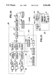
- FIG. 1 is a block diagram showing a partial configuration of a prior-art magnetic resonance imaging system 120, in which a plurality of surface coils 101A to 101C are arranged as a multicoil.
- the system comprises roughly a probe assembly 100, a data processing unit 105, and a display unit 111.
- the probe assembly 100 includes a plurality of small receiving coils 101A to 101C arranged on the same plane to pick up MR signals generated from an MR signal source, that is, an object under medical examination (not shown); a plurality of tuning/impedance matching circuits 102A to 102C for tuning the picked up MR signals and matching impedances of the coils with those of the succeeding stage, respectively; a plurality of preamplifiers 103A to 103C for amplifying the output signals of the coils respectively; and an adder 104.
- Each coil 101, circuit 102 and preamplifier 103 are connected in series, separately in this order. Therefore, MR signals outputted from the small receiving coils 101A to 101C are given to the adder 104 through the tuning/impedance matching circuits 102A to 102C and the preamplifiers 103A to 103C, respectively.
- the adder 104 selects the MR signal outputted from any desired single small receiving coil or adds the MR signals outputted from the plural small receiving coils, before transmitting the MR signals to the data processing unit 105.
- the MR signals are picked up at a small MR image region of the object under medical examination through the selected single small receiving coil.
- the MR signals are picked up over a large MR image region of the object under medical examination through the plural combined small receiving coils equivalent to a large receiving coil obtained by connecting the outermost contours of the combined small receiving coils.
- the data processing unit 105 includes a filter 106, a detector 107, an A/D converter 108, a memory 109, and an image reconstruction circuit 110. Therefore, MR signals within a predetermined frequency band can be obtained from the MR signals transmitted to the data processing unit 105 through the filter 106, picked up through the detector 107, converted into digital MR signals through the A/D converter 108, and then stored in the memory 109.
- These stored MR signal data are given to the image reconstruction circuit 110 for Fourier transformation so that an image of the object to be examined can be reconstructed on the basis of these MR signal data.
- the reconstructed image data are then given to the display unit (e.g. CRT) 111 to display a predetermined cross-sectional image of the object under medical examination in response to the reconstructed MR image signals.
- the display unit e.g. CRT
- the above-mentioned prior-art MR imaging system is disclosed in U.S. Pat. Nos. 4,825,162, 4,859,947 or 4,975,644, for instance, therefore these documents being incorporated by reference herein.
- the image obtained at a small MR image region is high in S/N ratio and image quality.
- the MR image region i.e. the visual field of MR image
- the image over a large MR image region is low in S/N ratio and image quality. This is because the effective sensitivity range of the receiving coil increases, with the result that the intensity of random noise received from an object under medical examination increase.
- the present invention provides a magnetic resonance imaging system comprising:
- a plurality of receiving coils (2-1:2-n for receiving a plurality of MR (magnetic resonance) signals generated from plural portions of an MR signal source (P);
- a plurality of filters (6-1-6n) coupled to said plural receiving coils, for filtering said plurality of MR signals to obtain a plurality of filtered MR signals;
- FIG. 1 is a block diagram showing a partial configuration of a prior-art magnetic resonance imaging system 120
- FIG. 2 is a block diagram showing a partial configuration of a first embodiment of the magnetic resonance imaging system 20 according to the present invention
- FIG. 3 is an illustration for assistance in explaining the sensitivity distribution of the small receiving coils 2-1 to 2-3 of the system 20 shown in FIG. 2;
- FIG. 4 is a graphical representation showing the relationship between the Larmor frequency ⁇ and the Z coordinates in the same embodiment
- FIGS. 5A to 5D are graphical representations showing the relationship between the Larmor frequencies and the signal levels of the small receiving coils 2-1 to 2-3, respectively, for assistance in explaining the reason why noise level increases when the signal levels of the small receiving coils are simply added;
- FIG. 6 is a graphical representation showing the signal level of the small receiving coil 2-n in the same embodiment
- FIG. 7 is a graphical representation showing the passband characteristics of the filter 6-n of the same embodiment.
- FIG. 8 is a graphical representation showing the signal level of the filter 6-n in the same embodiment.
- FIG. 9 is a graphical representation showing the signal level of the adder 7 of the same embodiment, in which signals outputted from all the small receiving coils 2-1 to 2-n are added;
- FIG. 10 is a graphical representations showing passband characteristics of the filters 6-1 to 6-n of the same embodiment
- FIG. 11 is a graphical representation showing the sum total of the signal levels of the filters 6-1 to 6-n;
- FIG. 12 is an illustration showing the positional relationship between the small receiving coils 2-1 to 2-n and the frame 13 in the same embodiment
- FIG. 13 is a block diagram showing the internal configuration of the filter 6-1 and the filter band setting circuit 12 in the same embodiment
- FIG. 14 is a block diagram showing a partial configuration of a second embodiment of the magnetic resonance imaging system 40 according to the present invention.
- FIG. 15 is a graphical representation showing the output of the mixer 5-n of the same embodiment.
- FIG. 16 is a block diagram showing a partial configuration of a third embodiment of the magnetic resonance imaging system 60 according to the present invention.
- FIG. 17 is an illustration showing another example of arrangement of the small receiving coils 2-1 to 2-n of the first to third embodiments of the imaging system according to the present invention.
- a plurality of small receiving coils for picking up MR signals generated from an MR signal source are arranged on the same plane.
- a plurality of filters of bandpass type are connected one by one to the small receiving coils for filtering only MR signals at predetermined frequency bands, respectively from the MR signals outputted from the respective small receiving coils.
- An adder is connected to these filters to output MR coils.
- An adder is connected to these filters to output MR signals filtered through a single filter or plural filters corresponding to a single selected or plural selected small receiving coils.
- the MR signals of predetermined different frequency bands can be obtained from the MR signals outputted from the respective small receiving coils through the filters of bandpass type, the MR signals of frequency bands corresponding to high sensitivity ranges (at which the MR signals can be picked up by the respective small receiving coils at high sensitivity) can be picked up, while eliminating noise of other frequency bands.
- the MR signals of frequency bands corresponding to the high sensitivity ranges of the respective small receiving coils and filtered through the respective filters are added with each other by the adder, MR signals over a large image region can be obtained.
- the respective frequency bands corresponding to the high sensitivity ranges of the respective small receiving coils are different from each other, it is possible to minimize the sum total of noise levels of the respective small receiving coils even if the respective MR signals outputted through the respective filters are added. That is, since MR signals can be picked up at high S/N ratio and over a large image region, it is possible to obtain an image of broad visual field in high quality.
- each small receiving coil since the frequency band of the high-frequency MR signals outputted from each small receiving coil can be transformed into low-frequency band signals, for instance through the mixer, it is possible to lower the operating frequency band of the filter and therefore to facilitate designing of a narrow passband filter, as compared with when designing a filter which operates within the frequency (Larmor frequency) band of the high-frequency MR signals and additionally have a passband much narrower than the Larmor frequency band.
- FIG. 2 is a block diagram showing a partial configuration of the first embodiment of the magnetic resonance imaging system 20 according to the present invention.
- a plurality of small receiving coils 2-1 to 2-n for picking up MR signals generated from an object under medical examination i.e. a MR signal source
- a receiving unit 1 of the imaging system 20 i.e. a MR signal source
- one of the small receiving coils 2-1 to 2-n There are connected in series one of the small receiving coils 2-1 to 2-n, one of tuning/impedance matching circuits 3-1 to 3-n for each tuning MR signals and matching impedance of the receiving coil with that of the succeeding stage, one of preamplifiers 4-1 to 4-n for each amplifying the MR signals outputted from the receiving coils, and one of bandpass filters 6-1 to 6-n for each filtering MR signals of a predetermined frequency band from the MR signals outputted from one of the preamplifiers 4-1 to 4-n.
- the passbands of these filters 6-1 to 6-n are different from each other, and the passband characteristics of each filter is programmable.
- an adder 7 is connected to these filters 6-1 to 6-n so as to transmit outputted from a single or plural filters selected from among the filters 6-1 to 6-n.
- MR signals outputted through a single or plural filters corresponding to a single or plural coils selected from among the small receiving coils 2-1 to 2-n can be obtained through the adder 7.
- a uniform static magnetic field generated by a magnet (not shown), a gradient magnetic field generated by a gradient magnetic field coil (not shown) and a high-frequency magnetic field generated by a transmitting unit (not shown) are simultaneously applied to an object under medical examination.
- MR signals generated from the object to be examined after the object has been released from the high-frequency magnetic field are picked up by the small receiving coils 2-1 to 2-n of the receiving unit 1.
- the high frequency MR signals picked up by the respective small receiving coils 2-1 to 2-n are transmitted to the respective filters 6-1 to 6-n via the respective tuning/impedance matching circuits 3-1 to 3-n and the respective preamplifiers 4-1 to 4-n.
- the filters 6-1 to 6-n filter MR signals of frequency bands corresponding to the high sensitivity ranges of the respective small receiving coils 2-1 to 2-n, respectively, from the MR signals from the preamplifiers 4-1 to 4-n.
- the adder 7 selects the MR signals outputted through only a single filter or adds the MR signals outputted through plural filters selected from among the filters 6-1 to 6-n, before transmitting the MR signals to a detector 8.
- the MR signals are converted into digital MR signal data via the A/D converter 9 and then given to a processor 10.
- the processor 10 processes the digital MR signal data in accordance with Fourier transformation, for instance to reconstruct an image of the object under medical examination on the basis of these data.
- the image signals thus reconstructed are transmitted from the processor 10 to a display unit 11 (e.g. CRT) to display a predetermined cross-sectional image of the object to be examined on the basis of these MR image data.
- a display unit 11 e.g. CRT
- the processor 10 gives respective passband information data for the respective passbands, to a filter band setting circuit 12.
- the filter band setting circuit 12 sets the respective passbands of the programmable filters 6-1 to 6-n. The method of setting these filter passbands will be described later in further detail.
- the above-mentioned plural small receiving coils 2-1 to 2-n have different sensitivity distributions, respectively.
- the three small receiving coils 2-1 to 2-3 are arranged near and along the Z-axis (longitudinal direction) of the human body P as shown in FIG. 3.
- the sensitivity distributions of the small receiving coils 2-1 to 2-3 at a Y-axis position of the object P under medical examination with respect to the Z-axis direction become as shown by curves a to c in FIG.
- spin echo or gradient echo technique is well known as the method of picking up MR signals from an object P under medical examination.
- a gradient magnetic field with respect to the Z-axis direction is applied to the object P so that the Larmor frequency differs along the Z-axis. That is, FIG. 4 shows the relationship between the Z-axis and the Larmor frequency ⁇ obtained when a gradient magnetic field is applied with the central position Z o as its center.
- FIG. 4 indicates that the Larmor frequency ⁇ o can be obtained at the central position Z o by the major magnetic field, and the Larmor frequency is offset by ⁇ when the length is offset by L in the Z-axis direction.
- FIGS. 5A to 5D show the relationship between the output signal level and the Larmor frequency ⁇ of each small receiving coil 2-1 to 2-3, respectively, in which the ordinate indicates the magnitude (e.g. power level) per unit frequency width of the signal outputted from each coil.
- the curves a' to c' denote power levels of the MR signals picked up by the small receiving coils 2-1 to 2-3, respectively.
- FIG. 5 indicates that if the object P distributes uniformly in the Z-axis direction, these curves a' to c' are considerably similar in shape to the sensitivity curves a to c shown in FIG. 3.
- Each small receiving coil 2-1 to 2-3 receives also random noise generated at all the frequency bands in addition to the MR signals.
- the power levels of random noise are shown as the lines n 1 to n 4 , respectively. It is possible to simply add the signals outputted from the small receiving coils 2-1 to 2-3, so that the MR signal d' as shown in FIG. 5D can be obtained over a region 3L three times wider than the Z-axis directional length L of each receiving coil 2-1 to 2-3, that is, with a frequency range three times broader than that of each receiving coil 2-1 to 2-3. In this case, however, since the noise power level n 4 also increases about three times higher than each noise level n 1 to n 3 , thus reducing the S/N ratio markedly.
- MR signals of frequency bands corresponding to the respective high sensitivity ranges of the respective small receiving coils 2-1 to 2-n are filtered from the MR signals picked up by the respective small receiving coils 2-1 to 2-n, by means of the passband-type filters 6-1 to 6-n, and noise of frequency bands other than the above is eliminated. This method of eliminating noise will be described hereinbelow.
- the passbands of the filters 6-1 to 6-n are adjustable and further determined so as to be roughly equal to the frequency bands corresponding to the high sensitivity ranges of the respective small receiving coils 2-1 to 2-n in response to passband setting signals 31 given from the filter band setting circuit 12 to the respective filters 6-1 to 6-n.
- the passband of the filter 6-n is determined so as to become roughly from ( ⁇ n- ⁇ /2) to ( ⁇ n+ ⁇ /2).
- FIG. 7 shows an example of the passband characteristics of the filter 6-n under these conditions. Therefore, MR signals of a frequency band roughly from ( ⁇ n- ⁇ /2) to ( ⁇ n+ ⁇ /2) can be outputted from the filter 6-n, as shown in FIG. 8. In other words, it is possible to eliminate noise of frequency band other than the above frequency band from the MR signals outputted from the small receiving coil 2-n.
- similarly MR signals of the frequency bands corresponding to the high sensitivity regions of the respective small receiving coils 2-1 to 2-(n-1) can be outputted through the respective filters 6-1 to 6-(n-1), from the MR signals picked up by the respective small receiving coils 2-1 to 2-(n-1), while eliminating noise of frequency bands other than the above.
- frequency passbands are set to the respective filters 6-1 to 6-(n-1) in such a way as to have a width ⁇ with the respective Larmor frequencies ⁇ 1 to ⁇ n-1 as the respective centers at the central positions of the respective small receiving coils 2-1 to 2-(n-1), in the same way as with the case of the filter 6-n.
- the method of setting the passbands of the filters 6-1 to 6-n will be described in further detail hereinbelow.
- the processor 10 calculates a differential value ⁇ between the Larmor frequencies ⁇ 1 to ⁇ n at the central positions of the respective small receiving coils and the Larmor frequency corresponding to the pitch of the small receiving coils as follows:
- FIG. 12 shows the positional relationship between various elements related to the frequencies ⁇ 1 to ⁇ n and ⁇ .
- a bed 14 is fixed to the frame 13.
- a top plate 15 on the bed 14 is movable in the Z-axis direction.
- a coil assembly 16 is arranged on the top plate 15, and the object P under medical examination is placed on the coil assembly 16.
- the X-Y-Z coordinates are determined as shown in FIG. 12.
- the coil assembly 16 is fixed on the top plate 15 by various appropriate means such as pins, screws, convex and concave engagement, etc.
- the small receiving coils 2-1 to 2-n there are arranged the small receiving coils 2-1 to 2-n, the tuning/impedance matching circuits 3-1 to 3-n, and the preamplifiers 4-1 to 4-n, respectively.
- the filters 6-1 to 6-n and the adder 7 are not necessarily mounted in the coil assembly 16.
- points P 1 to P n denote the respective central positions of the small receiving coils 2-1 to 2-n, and a distance L denotes an interval between the two adjoining coil central positions P 1 to P n .
- the central position P 1 of the small receiving coil 2-1 is located a distance D away from the central position of the frame 13. Therefore, when the top plate 15 is fed into the frame 13 by a distance T from the initial position, this distance T is sensed by an encoder 17 mounted on the bed 14, and a sensor signal 32 is given from the encoder 17 to the processor 10 as shown in FIG. 2, so that the processor 10 can recognize this distance T.
- the magnetic field intensity B (obtained when a gradient magnetic field G z is applied in the Z-axis direction) can be calculated by the formula as
- B o denotes the static magnetic field intensity
- Z denotes the Z coordinate position.
- the intensity of this G z is previously known by the processor 10, since the control signal from the processor 10 to the power supply (not shown) for gradient coil (not shown) is only one variable to determine G z . Further, the magnetic field B 1 at the central position P 1 of the small receiving coil 2-1 can be calculated as
- the Larmor frequency ⁇ 1 at the central position P 1 can be obtained as follows:
- the Larmor frequency ⁇ n at the central position P n of the small receiving coil 2-n can be calculated in accordance with the following formula:
- FIG. 13 is a block diagram showing the internal configuration of the filter 6-1 and the filter passband setting circuit 12.
- the processor 10 determines the passband lower and upper limits of the filter 6-1 on the basis of the Larmor frequency ⁇ 1 and ⁇ as follows:
- the determined limit information data ⁇ 1L and ⁇ 1H are transmitted to the registers REG-1H and REG-1L via an interface 18 as passband information signals 33 and then stored therein as passband data.
- the register REG-1L supplies the passband control signal (digital signal) 31A corresponding to the data ⁇ 1H to the programmable low-pass filter 6A-1; and the register REG-1H supplies the passband control signal (digital signal) 31B corresponding to the data W 1L to the programmable high-pass filter 6B-1.
- the passband upper limit ⁇ 1H of the LPF 6A-1 is determined by the passband control signal 31A and the passband lower limit ⁇ 1L of the HPF 6B-1 is determined by the passband control signal 31B, so that the passband between ⁇ 1L and ⁇ 1H of the filter 6-1, that is, the frequency range can be determined so as to correspond to the high sensitivity range of the small receiving coil 2-1.
- the output of the adder 7 as shown in FIG. 9 can be obtained in the case where the bandpass width of each of the filters 6-1 to 6-n is selected as roughly ⁇ as shown in FIG. 7.
- the level of noise n is roughly equal to that included in the MR signals picked up by a single small receiving coil, so that it is possible to minimize the noise level, as compared with the case where no filters 6-1 to 6-n are provided as shown in FIG. 5D.
- the signal level of the MR signal S drops at frequency bands corresponding to those other than the boundaries between two adjacent high sensitivity ranges of the respective small receiving coils 2-1 to 2-n.
- this drop phenomenon in the signal level is predictable and therefore reproducible, it is possible to readily correct these drops in power level with respect to the Larmor frequency by executing sensitivity correction processing for the final image, for instance.
- the passband characteristics of the filters 6-1 to 6-n can be modified in various ways by changing the rising and/or falling edges of the passband characteristics, without being limited to only those shown in FIG. 7, as far as the sensitivity profile obtained by connecting all the outputs of the coils is not excessively distorted.
- the bandpass widths of the filters 6-1 to 6-n are much wider than ⁇ , respectively as shown in FIG. 10
- the sum total of the signal levels of the filters 6-1 to 6-n can be represented as shown in FIG. 11, in which S' denotes the MR signal level and n' denotes the noise level.
- a single small receiving coil is selected from the small receiving coils 2-1 to 2-n, and the MR signals outputted form the single small receiving coil are outputted by the adder 7 via the filter corresponding to the small receiving coil, it is possible to pick up the MR signal at a small image region at high S/N ratio and therefore to obtain an image in a narrow visual field and a high image quality.
- the MR signals outputted from a plurality of small receiving coils are transmitted to the adder 7 via the filters corresponding to the respective small receiving coils, and the add 7 adds these filtered MR signals, it is possible to pick up the MR signals at a large image region at high S/N ratio and therefore to also obtain an image in a wide field and a high image quality. Since any required image region can be selected easily by switching the inputs of the adder 7 without changing the locations of the receiving coils relative to the object P under medical examination, it is possible to improve the easiness of system operation and the easiness of patient handling.
- FIG. 14 is a block diagram showing a partial configuration of a second embodiment of the magnetic resonance imaging system 40 according to the present invention, in which the same references shown in FIG. 2 have been retained for similar elements having the same functions, without repeating the description thereof. Only the elements different from those shown in FIG. 2 will be described hereinbelow.
- Mixers 5-1 to 5-n transform the respective output frequencies of the preamplifiers 4-1 to 4-n into different frequencies, respectively.
- a reference signal 41 indicative of a reference frequency ⁇ r (as described later) is applied from a synthesize 21 of a filter control circuit 112.
- Each of the mixers 5-1 to 5-n outputs a first signal with a frequency obtained by adding the reference frequency ⁇ r to each frequency of each output of the preamplifiers 4-1 to 4-n and a second signal with a frequency obtained by subtracting the reference frequency ⁇ r from each frequency thereof, in response to the reference signal 41. In this embodiment, only the second signals are transmitted.
- FIG. 15 shows the frequency distribution of the second signal outputted form the mixer 5-n together with that of noise, by way of example.
- the frequency passbands of the filters 116-1 to 116-n are lowered by ⁇ r as compared with these frequency passbands of the filters 6-1 to 6-n of the first embodiment.
- the passband widths of these filters are the same as in the first embodiment. Therefore, since the frequencies of the first signals outputted from the respective mixers 5-1 to 5-n are out of the passbands of the filters 116-1 to 116-n, the first signals are eliminated by the filters 116-1 to 116-n, and only the second signals outputted from the respective mixers can pass through the respective filters 116-1 to 116-n.
- the filters 116-1 to 116-n can be designed very easily. Additionally, in the second embodiment, since the MR signals of the high Larmor frequency band are transformed into signals of low frequency band through the mixers 5-1 to 5-n, it is possible to use relatively low-costly low-frequency filters as the filter 116-1 to 116-n.
- Another mixer 22 serves to return the low-frequency output signals of the adder 7 to the original high frequency signals. Since the reference signal 41 is also supplied to this mixer 22, the mixer 22 outputs a first signal with a frequency obtained by adding the reference frequency ⁇ r to the output frequency of the adder 7 and a second signals with a frequency obtained by adding the reference frequency ⁇ r to the output frequency of the adder 7 and a second signal with a frequency obtained by subtracting ⁇ r therefrom, both the signals being applied to a high-pass filter 23. However, only the first signal of the output signals from the mixer 22 passes through the high-pass filter 23 to eliminate the second signal.
- the mixer 22 and the high-pass filter 23 are not both provided, since the frequency band of the output signals of the receiving unit 51 of the second embodiment is quite different from that of the output signals of the ordinary receiving coil, another different detector (a detector different from that used for the ordinary receiving coil) must be prepared. In the second embodiment, however, since the mixer 22 and the high-pass filter 23 are provided, it is possible to use the detector for the ordinary receiving coil as a detector 8 of the second embodiment. Further, if the detector 8 has functions to eliminate signals of frequency bands quite different from the Larmor frequency bands, the high-pass filter 23 is not necessary to be provided.
- the processor 10 first sets the reference frequency ⁇ r , transmits a reference frequency information signal 42 corresponding to the reference frequency ⁇ r to the register 25 via the interface 24, and stores it in the register 25 as a reference frequency data.
- the reference frequency ⁇ r can be truly selected to any given value suitable for the whole system. However, in this embodiment, it is preferred to select the reference frequency ⁇ r a little lower than the Larmor frequency.
- the synthesizer 21 outputs a reference signal 41 of the reference frequency ⁇ r stored in the register 25 to the respective mixers 5-1 to 5-n.
- the processor 10 determines the lower and upper limits of the passbands of the respective filters 116-1 to 116-n as described later, transmits the passband information signals 133 to the register 27 via the interface 24, and stores them as passband data. Further, in FIG. 14, although only a single register 27 is shown for simplification, in practice a necessary number of registers 27 are required to store the respective passband lower and upper limit data for the respective filters 116-1 to 116-n. These filters 116-1 to 116-n are of programmable bandpass type in the same way as the filters 6-1 to 6-n.
- the register 27 supplies passband control signals 131 corresponding to the data representative of the passband lower and upper limits of the respective filters 116-1 to 116-n, to the filters 161-1 to 116-n to determine the respective passbands of the respective filters 116-1 to 116-n.
- the processor 10 determines the passband lower and upper limits of the filter 116-1, for instance as follows:
- K is set to approximately 1. However, if flat sensitivity distribution characteristics are required at the sacrifice of the noise elimination effect, K is set to a value of more than 1, as already explained with respect to the first embodiment. The same is applicable to other filters 116-1 to 116-n. That is, the passband lower and upper limits of the filter 116-2 are determined as
- the passband lower and upper limits of the other filters 116-3 to 116-n can be determined in the same way being offset ⁇ G z ⁇ L by ⁇ G z ⁇ L.
- FIG. 16 is a block diagram showing a partial configuration of a third embodiment of the magnetic resonance imaging system 60 according to the present invention, in which the same references shown in FIG. 14 have been retained for similar elements having the same functions, without repeating the description thereof. Only the elements different from those shown in FIG. 14 will be described hereinbelow.
- Mixers 215-1 to 215-n of the receiving unit 61 of the system 60 transform the respective output frequencies of the preamplifiers 4-1 to 4-n into different frequencies, respectively in the same way as with the case of the mixers 5-1 to 5-n.
- different reference signals 241-1 to 241-n of different reference frequencies ⁇ 1r to ⁇ 1n are supplied from a synthesizer 221 of a filter group control circuit 212 to the mixers 215-1 to 215-n, respectively.
- the reference frequency ⁇ 2r for the mixer 215-2 is set as
- the reference frequencies ⁇ 3r to ⁇ nr for the other mixers 215-3 to 215-n are set in the same way being offset ⁇ G z ⁇ L by ⁇ G z ⁇ L.
- frequencies of the output signals of the mixers 215-1 to 215-n lie within the same frequency range.
- the output signals of the mixers 215-1 to 215-n are the same in frequency.
- the second signal outputted from the mixer 215-1 is the same in frequency as that from the mixer 215-2.
- the frequency ranges of the output signals of all the mixers 215-1 to 215-n are equal to each other.
- the passband lower and upper limits of the filters 216-1 to 216-n are set as follows:
- the reference signals 241-1 to 241-n with reference frequencies ⁇ 1r to ⁇ nr are also applied to the mixers 222-1 to 222-n, respectively from the synthesizer 221.
- the respective mixers 215-1 to 215-n generate signals whose frequencies are returned to those of the signals outputted by the small receiving coils 2-1 to 2-n, by adding the respective reference frequencies ⁇ 1r to ⁇ nr to the frequencies of the output signal of the respective filters 216-1 to 216-n.
- the respective mixers 215-1 to 215-n generate signal whose frequencies are obtained by subtracting the respective reference frequencies ⁇ 1r to ⁇ rn from the frequencies of the output signals of the respective filters 216-1 to 216-n, these signals are eliminated through the high-pass filter 23.
- the processor 10 transmits reference frequency information signals 242 indicative of the respective reference frequencies ⁇ 1r to ⁇ nr (to be supplied to the respective mixers 215-1 to 215-n) to a register 225 via an interfacer 224, and stores them in the register 225 as the reference frequency data.
- reference frequency information signals 242 indicative of the respective reference frequencies ⁇ 1r to ⁇ nr (to be supplied to the respective mixers 215-1 to 215-n) to a register 225 via an interfacer 224, and stores them in the register 225 as the reference frequency data.
- the synthesizer 221 In response to the signals from the register 225, the synthesizer 221 outputs the respective reference signals 241-1 to 214-n of the respective reference frequencies ⁇ 1r to ⁇ nr to the respective mixers 215-1 to 215-n and 222-1 to 222-n.
- the processor 10 transmits passband information signals 233 indicative of the passband lower and upper limits ⁇ 21L and ⁇ 21H of the filters 216-1 to 216-n to a register 227 via the interface 224 and stores them in the register 227 as the passband data.
- the register 227 supplies passband control signals 213 according to the data indicative of the passband lower and upper limits ⁇ 21L and ⁇ 21H to the respective filters 216-1 to 216-n to set the passbands ⁇ 21L to ⁇ 21H of the respective filters 216-1 to 216-n.
- the small receiving coils 2-1 to 2-n are arranged side by side on the same plane without being overlapped with each other. Without being limited thereto, it is also possible to arrange the small receiving coils 2-1 to 2-n so as to be overlapped with each other as shown in FIG. 17. In the case where the respective small receiving coils are overlapped with each other, there exists such an advantage that the intensity of the electromagnetic coupling between the two overlapped small receiving coils is reduced. As described above, the present invention is operative and effective even if the pitch 1 between the two overlapped small receiving coils 2-1 to 2-n is determined shorter than the length L of each small receiving coil 2-1 to 2-n.
- Embodiments of the present invention has been explained by way of example. Without being limited thereto, however, various modification can be made.
- the small receiving coils 2-1 to 2-n are arranged in the direction of the static magnetic field, that is, on the same plane in the Z-axis direction.
- the present invention is operative even when these small receiving coils 2-1 to 2-n are arranged in the X-axis direction or the Y-axis direction.
- the small receiving coils 2-1 to 2-n are arranged on the same plane in the X-axis direction, and further the filter passbands are controlled according to the intensity of the grandient magnetic field applied in the X-axis direction and the X-coordinates of the small receiving coils 2-1 to 2-n, in the same way as in the first to third embodiments. The same is applicable to the Y-axis direction.
Landscapes
- Physics & Mathematics (AREA)
- Condensed Matter Physics & Semiconductors (AREA)
- General Physics & Mathematics (AREA)
- Magnetic Resonance Imaging Apparatus (AREA)
Applications Claiming Priority (2)
| Application Number | Priority Date | Filing Date | Title |
|---|---|---|---|
| JP02188139A JP3110741B2 (ja) | 1990-07-18 | 1990-07-18 | 磁気共鳴イメージング装置 |
| JP2-188139 | 1990-07-18 |
Publications (1)
| Publication Number | Publication Date |
|---|---|
| US5243288A true US5243288A (en) | 1993-09-07 |
Family
ID=16218428
Family Applications (1)
| Application Number | Title | Priority Date | Filing Date |
|---|---|---|---|
| US07/731,074 Expired - Fee Related US5243288A (en) | 1990-07-18 | 1991-07-16 | Multiple coil type magnetic resonance imaging system including filters with different passbands |
Country Status (4)
| Country | Link |
|---|---|
| US (1) | US5243288A (de) |
| EP (1) | EP0467378B1 (de) |
| JP (1) | JP3110741B2 (de) |
| DE (1) | DE69130195T2 (de) |
Cited By (9)
| Publication number | Priority date | Publication date | Assignee | Title |
|---|---|---|---|---|
| DE4412446A1 (de) * | 1994-04-12 | 1995-10-19 | Bruker Medizintech | Verfahren und Vorrichtung zur Erstellung eines NMR-Tomographiebildes |
| US5587656A (en) * | 1994-04-08 | 1996-12-24 | U.S. Philips Corporation | Magnetic resonance imaging method and apparatus |
| US20020016696A1 (en) * | 2000-01-28 | 2002-02-07 | Siemens Aktiengesellschaft | Method for selecting a local antenna for use in producing image data in a diagnostic magnetic resonance apparatus |
| US20050218895A1 (en) * | 1997-11-26 | 2005-10-06 | Belt Kenneth W | Peripheral vascular array |
| US20070126425A1 (en) * | 2005-12-02 | 2007-06-07 | Kabushiki Kaisha Toshiba | MRI apparatus |
| US20090224763A1 (en) * | 2007-12-06 | 2009-09-10 | Koninklijke Philips Electronics N.V. | Method and apparatus for lossless or low loss coupling for many channel rf coil arrays |
| US20100329527A1 (en) * | 2009-06-29 | 2010-12-30 | Joseph Iannotti | System and apparatus for frequency translation of magnetic resonance (mr) signals |
| US20160109613A1 (en) * | 2014-10-16 | 2016-04-21 | Schlumberger Technology Corporation | Methods And Apparatuses For Echo Processing Of Nuclear Magnetic Resonance (NMR) Data |
| US20160163047A1 (en) * | 2014-12-05 | 2016-06-09 | Samsung Electronics Co., Ltd. | Magnetic resonance imaging apparatus and method of generating magnetic resonance image |
Families Citing this family (9)
| Publication number | Priority date | Publication date | Assignee | Title |
|---|---|---|---|---|
| EP0554584A1 (de) * | 1991-11-29 | 1993-08-11 | Koninklijke Philips Electronics N.V. | Magnetische Resonanzanordnung und Signalkombinationsanordnung |
| US6134465A (en) * | 1998-06-12 | 2000-10-17 | General Electric Company | Method for reducing artifacts in MR image acquired with phased array surface coil |
| GB2357149A (en) * | 1999-12-08 | 2001-06-13 | Topspin Medical | MRI using non-homogeneous static field |
| JP4607928B2 (ja) * | 2004-04-23 | 2011-01-05 | ジーイー・メディカル・システムズ・グローバル・テクノロジー・カンパニー・エルエルシー | 画像生成方法およびmri装置 |
| EP1825287A2 (de) * | 2004-12-06 | 2007-08-29 | Koninklijke Philips Electronics N.V. | Frequenzbereichsmultiplexübertragung von mr-signalen von einer empfängerspulengruppe |
| JP4740009B2 (ja) * | 2006-03-28 | 2011-08-03 | ジーイー・メディカル・システムズ・グローバル・テクノロジー・カンパニー・エルエルシー | 磁気共鳴撮像装置、rfコイル及び磁気共鳴撮像装置の制御方法 |
| JP5268287B2 (ja) * | 2006-06-07 | 2013-08-21 | 株式会社東芝 | アレイコイルおよび磁気共鳴イメージング装置 |
| WO2009070717A1 (en) * | 2007-11-27 | 2009-06-04 | Kim Jae K | Noise reduction by means of spectral parallelism |
| CN106226715A (zh) * | 2016-09-12 | 2016-12-14 | 厦门大学 | 磁共振数字接收系统 |
Citations (11)
| Publication number | Priority date | Publication date | Assignee | Title |
|---|---|---|---|---|
| US4439733A (en) * | 1980-08-29 | 1984-03-27 | Technicare Corporation | Distributed phase RF coil |
| US4780677A (en) * | 1986-05-13 | 1988-10-25 | Elscint Ltd. | Probe for nuclear magnetic resonance systems |
| US4825162A (en) * | 1987-12-07 | 1989-04-25 | General Electric Company | Nuclear magnetic resonance (NMR) imaging with multiple surface coils |
| US4859947A (en) * | 1986-11-27 | 1989-08-22 | U.S. Philips Corporation | Magnetic resonance imaging apparatus comprising a stacked surface coil system |
| US4885541A (en) * | 1988-08-19 | 1989-12-05 | General Electric Company | Apparatus and method for enhanced multiple coil nuclear magnetic resonance (NMR) imaging |
| US4924868A (en) * | 1987-02-17 | 1990-05-15 | Siemens Aktiengesellschaft | Surface coil for a nuclear magnetic resonance apparatus |
| EP0374994A1 (de) * | 1988-12-01 | 1990-06-27 | Koninklijke Philips Electronics N.V. | HF-Spulensystem mit mehreren Oberflächenspulen |
| EP0384770A2 (de) * | 1989-02-23 | 1990-08-29 | Kabushiki Kaisha Toshiba | Verfahren zur Kernspindarstellung |
| EP0390476A2 (de) * | 1989-03-29 | 1990-10-03 | Kabushiki Kaisha Toshiba | Spulensystem für einen Kernspinresonazapparat zur Abbildung |
| EP0407579A1 (de) * | 1988-02-15 | 1991-01-16 | Yokogawa Medical Systems, Ltd | Bildformungsanordnung mittels magnetischer resonanz |
| US5132621A (en) * | 1990-04-24 | 1992-07-21 | General Electric Company | Radio frequency field coil and power splitter for nmr |
Family Cites Families (2)
| Publication number | Priority date | Publication date | Assignee | Title |
|---|---|---|---|---|
| US4737713A (en) | 1986-11-26 | 1988-04-12 | Fonar Corporation | Apparatus and method for processing an electrical signal and increasing a signal-to-noise ratio thereof |
| NL9001298A (nl) * | 1990-06-08 | 1992-01-02 | Philips Nv | Rf spoelenstelsel in magnetisch resonantie apparaat. |
-
1990
- 1990-07-18 JP JP02188139A patent/JP3110741B2/ja not_active Expired - Fee Related
-
1991
- 1991-07-16 US US07/731,074 patent/US5243288A/en not_active Expired - Fee Related
- 1991-07-18 EP EP91112063A patent/EP0467378B1/de not_active Expired - Lifetime
- 1991-07-18 DE DE69130195T patent/DE69130195T2/de not_active Expired - Fee Related
Patent Citations (12)
| Publication number | Priority date | Publication date | Assignee | Title |
|---|---|---|---|---|
| US4439733A (en) * | 1980-08-29 | 1984-03-27 | Technicare Corporation | Distributed phase RF coil |
| US4780677A (en) * | 1986-05-13 | 1988-10-25 | Elscint Ltd. | Probe for nuclear magnetic resonance systems |
| US4859947A (en) * | 1986-11-27 | 1989-08-22 | U.S. Philips Corporation | Magnetic resonance imaging apparatus comprising a stacked surface coil system |
| US4924868A (en) * | 1987-02-17 | 1990-05-15 | Siemens Aktiengesellschaft | Surface coil for a nuclear magnetic resonance apparatus |
| US4825162A (en) * | 1987-12-07 | 1989-04-25 | General Electric Company | Nuclear magnetic resonance (NMR) imaging with multiple surface coils |
| EP0407579A1 (de) * | 1988-02-15 | 1991-01-16 | Yokogawa Medical Systems, Ltd | Bildformungsanordnung mittels magnetischer resonanz |
| US4885541A (en) * | 1988-08-19 | 1989-12-05 | General Electric Company | Apparatus and method for enhanced multiple coil nuclear magnetic resonance (NMR) imaging |
| EP0374994A1 (de) * | 1988-12-01 | 1990-06-27 | Koninklijke Philips Electronics N.V. | HF-Spulensystem mit mehreren Oberflächenspulen |
| EP0384770A2 (de) * | 1989-02-23 | 1990-08-29 | Kabushiki Kaisha Toshiba | Verfahren zur Kernspindarstellung |
| EP0390476A2 (de) * | 1989-03-29 | 1990-10-03 | Kabushiki Kaisha Toshiba | Spulensystem für einen Kernspinresonazapparat zur Abbildung |
| US4975644A (en) * | 1989-03-29 | 1990-12-04 | Kabushiki Kaisha Toshiba | Coil system for a magnetic resonance imaging system |
| US5132621A (en) * | 1990-04-24 | 1992-07-21 | General Electric Company | Radio frequency field coil and power splitter for nmr |
Cited By (18)
| Publication number | Priority date | Publication date | Assignee | Title |
|---|---|---|---|---|
| US5587656A (en) * | 1994-04-08 | 1996-12-24 | U.S. Philips Corporation | Magnetic resonance imaging method and apparatus |
| DE4412446A1 (de) * | 1994-04-12 | 1995-10-19 | Bruker Medizintech | Verfahren und Vorrichtung zur Erstellung eines NMR-Tomographiebildes |
| US5572130A (en) * | 1994-04-12 | 1996-11-05 | Bruker Medizintechniik Gmbh | Method and apparatus for the production of an NMR tomography image using an array of surface coils and multiplexers |
| US20050218895A1 (en) * | 1997-11-26 | 2005-10-06 | Belt Kenneth W | Peripheral vascular array |
| US7141980B2 (en) * | 1997-11-26 | 2006-11-28 | Medrad, Inc. | Apparatuses for enabling operation of adjacent coil loops with a magnetic resonance system |
| US20020016696A1 (en) * | 2000-01-28 | 2002-02-07 | Siemens Aktiengesellschaft | Method for selecting a local antenna for use in producing image data in a diagnostic magnetic resonance apparatus |
| US6792257B2 (en) * | 2000-01-28 | 2004-09-14 | Siemens Aktiengesellschaft | Method for selecting a local antenna for use in producing image data in a diagnostic magnetic resonance apparatus |
| US7365541B2 (en) * | 2005-12-02 | 2008-04-29 | Kabushiki Kaisha Toshiba | MRI apparatus which automatically determines and displays operating instructions |
| US20070126425A1 (en) * | 2005-12-02 | 2007-06-07 | Kabushiki Kaisha Toshiba | MRI apparatus |
| US20090224763A1 (en) * | 2007-12-06 | 2009-09-10 | Koninklijke Philips Electronics N.V. | Method and apparatus for lossless or low loss coupling for many channel rf coil arrays |
| CN101971044A (zh) * | 2007-12-06 | 2011-02-09 | 皇家飞利浦电子股份有限公司 | 包括具有两个前置放大器的线圈元件的rf线圈阵列 |
| CN101971044B (zh) * | 2007-12-06 | 2015-04-22 | 皇家飞利浦电子股份有限公司 | 包括具有两个前置放大器的线圈元件的rf线圈阵列 |
| US20100329527A1 (en) * | 2009-06-29 | 2010-12-30 | Joseph Iannotti | System and apparatus for frequency translation of magnetic resonance (mr) signals |
| US8686725B2 (en) * | 2009-06-29 | 2014-04-01 | General Electric Company | System and apparatus for frequency translation of magnetic resonance (MR) signals |
| US20160109613A1 (en) * | 2014-10-16 | 2016-04-21 | Schlumberger Technology Corporation | Methods And Apparatuses For Echo Processing Of Nuclear Magnetic Resonance (NMR) Data |
| US10088594B2 (en) * | 2014-10-16 | 2018-10-02 | Schlumberger Technology Corporation | Methods and apparatuses for echo processing of nuclear magnetic resonance (NMR) data |
| US20160163047A1 (en) * | 2014-12-05 | 2016-06-09 | Samsung Electronics Co., Ltd. | Magnetic resonance imaging apparatus and method of generating magnetic resonance image |
| US9804236B2 (en) * | 2014-12-05 | 2017-10-31 | Samsung Electronics Co., Ltd. | Magnetic resonance imaging apparatus and method of generating magnetic resonance image |
Also Published As
| Publication number | Publication date |
|---|---|
| JPH0475636A (ja) | 1992-03-10 |
| DE69130195T2 (de) | 1999-06-02 |
| EP0467378A2 (de) | 1992-01-22 |
| DE69130195D1 (de) | 1998-10-22 |
| EP0467378B1 (de) | 1998-09-16 |
| EP0467378A3 (en) | 1992-05-27 |
| JP3110741B2 (ja) | 2000-11-20 |
Similar Documents
| Publication | Publication Date | Title |
|---|---|---|
| EP0467378B1 (de) | NMR-Abbildungssystem mit mehreren Spulen und Filter mit verschiednen Bandbreiten | |
| US5578925A (en) | Vertical field quadrature phased array coil system | |
| US5592088A (en) | Multiple-coil adopting a quadrature detection method applied thereto and a signal processing circuit employing the same in an MRI apparatus in a vertical magnetic system | |
| US5543711A (en) | Multiple quadrature volume coils for magnetic resonance imaging | |
| US7183770B2 (en) | High-frequency system for an MR apparatus with multiple transmit channels | |
| US9274189B2 (en) | High-frequency coil unit and magnetic resonance imaging device | |
| JP4891539B2 (ja) | 高周波コイルアセンブリ及び磁気共鳴撮像装置 | |
| US7123012B2 (en) | Multiple tuned radio frequency coil for resonance imaging and spectroscopic analysis | |
| US5552707A (en) | RF probe which can vary distance between receiving coils which face each other | |
| JP3727469B2 (ja) | 受信信号処理回路およびmri装置 | |
| JPH1043161A (ja) | 円筒形コイルシステム及び表面コイルシステムを設けたmr装置 | |
| JPH0614901A (ja) | 磁気共鳴イメージング装置 | |
| JPH05269111A (ja) | 磁気共鳴装置及び信号結合装置 | |
| US10197646B2 (en) | Decoupling of parallel transmission arrays in magnetic resonance imaging | |
| US7245127B2 (en) | Cervical-thoracic-lumbar spine phased array coil for horizontal field MRI systems | |
| US5272437A (en) | RF coil system in a magnetic resonance imaging apparatus | |
| JP2680235B2 (ja) | 核磁気共鳴装置用プローブ | |
| JP3706435B2 (ja) | 磁気共鳴装置のアンテナ装置の感度プロフィールを補償する装置 | |
| JP3197262B2 (ja) | 磁気共鳴映像装置 | |
| JPH05154128A (ja) | Nmr信号処理方法および装置 | |
| JP2564428B2 (ja) | 核磁気共鳴装置 | |
| JPH0542125A (ja) | 核磁気共鳴装置 | |
| JP3115028B2 (ja) | Rfプローブ | |
| JP5492171B2 (ja) | 磁気共鳴撮像装置 | |
| JP4350889B2 (ja) | 高周波コイル及び磁気共鳴イメージング装置 |
Legal Events
| Date | Code | Title | Description |
|---|---|---|---|
| AS | Assignment |
Owner name: KABUSHIKI KAISHA TOSHIBA Free format text: ASSIGNMENT OF ASSIGNORS INTEREST.;ASSIGNOR:MORI, ISSEI;REEL/FRAME:005785/0005 Effective date: 19910710 |
|
| FEPP | Fee payment procedure |
Free format text: PAYOR NUMBER ASSIGNED (ORIGINAL EVENT CODE: ASPN); ENTITY STATUS OF PATENT OWNER: LARGE ENTITY |
|
| FPAY | Fee payment |
Year of fee payment: 4 |
|
| FPAY | Fee payment |
Year of fee payment: 8 |
|
| REMI | Maintenance fee reminder mailed | ||
| LAPS | Lapse for failure to pay maintenance fees | ||
| LAPS | Lapse for failure to pay maintenance fees |
Free format text: PATENT EXPIRED FOR FAILURE TO PAY MAINTENANCE FEES (ORIGINAL EVENT CODE: EXP.); ENTITY STATUS OF PATENT OWNER: LARGE ENTITY |
|
| STCH | Information on status: patent discontinuation |
Free format text: PATENT EXPIRED DUE TO NONPAYMENT OF MAINTENANCE FEES UNDER 37 CFR 1.362 |
|
| FP | Lapsed due to failure to pay maintenance fee |
Effective date: 20050907 |