US5230076A - Ionospheric sounding - Google Patents
Ionospheric sounding Download PDFInfo
- Publication number
- US5230076A US5230076A US06/807,972 US80797285A US5230076A US 5230076 A US5230076 A US 5230076A US 80797285 A US80797285 A US 80797285A US 5230076 A US5230076 A US 5230076A
- Authority
- US
- United States
- Prior art keywords
- receiver
- sounding system
- code
- frequency
- ionospheric sounding
- Prior art date
- Legal status (The legal status is an assumption and is not a legal conclusion. Google has not performed a legal analysis and makes no representation as to the accuracy of the status listed.)
- Expired - Lifetime
Links
Images


Classifications
-
- G—PHYSICS
- G01—MEASURING; TESTING
- G01S—RADIO DIRECTION-FINDING; RADIO NAVIGATION; DETERMINING DISTANCE OR VELOCITY BY USE OF RADIO WAVES; LOCATING OR PRESENCE-DETECTING BY USE OF THE REFLECTION OR RERADIATION OF RADIO WAVES; ANALOGOUS ARRANGEMENTS USING OTHER WAVES
- G01S13/00—Systems using the reflection or reradiation of radio waves, e.g. radar systems; Analogous systems using reflection or reradiation of waves whose nature or wavelength is irrelevant or unspecified
- G01S13/02—Systems using reflection of radio waves, e.g. primary radar systems; Analogous systems
- G01S13/0218—Very long range radars, e.g. surface wave radar, over-the-horizon or ionospheric propagation systems
-
- H—ELECTRICITY
- H04—ELECTRIC COMMUNICATION TECHNIQUE
- H04B—TRANSMISSION
- H04B17/00—Monitoring; Testing
- H04B17/30—Monitoring; Testing of propagation channels
- H04B17/309—Measuring or estimating channel quality parameters
-
- H—ELECTRICITY
- H04—ELECTRIC COMMUNICATION TECHNIQUE
- H04B—TRANSMISSION
- H04B7/00—Radio transmission systems, i.e. using radiation field
- H04B7/22—Scatter propagation systems, e.g. ionospheric, tropospheric or meteor scatter
Definitions
- the invention relates to an ionospheric sounding unit for providing information to improve HF communications utilising long range sky-wave paths.
- Intermodulation frequency products caused by the non-linearities in the transmitters and by the ships superstructure can however be avoided by judicious frequency planning although this will inevitably reduce the available spectrum that can be used. Moreover this can only be accomplished if narrow-band systems are used and provided the higher order products can be ignored. If transmitter powers were to be increased these higher order products will become progressively more significant and will have to be considered in any subsequent frequency planning arrangements.
- the object of the present invention is to improve the performance of HF communications by means of judicious exploitation of the HF spectrum by real-time channel sounding.
- the object is to provide a low power ionospheric sounder which will permit a real-time assessment of the quality of different frequency bands in the HF spectrum thereby enabling improved communications links to be established using an optomised choise of frequencies.
- the invention consists of an ionospheric sounding system for providing frequency management information for high frequency (HF) communications comprising:
- a. a HF radio transmitter having:
- frequency selection means operating such that pulses of energy can be transmitted at respective frequencies pseudo-randomly selected from the HF range of radio frequencies
- modulation means to modulate each transmitted pulse with a code having an impulsive autocorrelation function
- a remote HF radio receiver having:
- frequency selection means capable of being programmed to sensitise the receiver to the transmitted sequence of pseudo-random frequencies
- correlation means for correlating the received signal during each pulse interval with a replica of the transmitted code and producing an output signal indicating detection of a transmitted signal.
- impulsive autocorrelation function applied herein to the code modulating the transmitted signal is a noise-like function with no recognizable pattern.
- the correlation function is zero or near zero everywhere except when the modulated signal is in exact register with its replica at which time the correlation is high.
- the code is a complementary code having two parts whose separate autocorrelation functions add to produce an impulsive function.
- dsb AM double side band amplitude modulation
- the transmitter is provided with a time code modem and a modulation control, the modulation control selectively connecting the sounding code or the time code to the modulation means.
- the receiver is provided with a similar time code modem to provide time of day information and facilitate synchronising of the receiver with the received signal.
- the two parts of the complementary code are separated by greater than about 10 ms to prevent corruption of the second received part by echo signals of the first received part.
- the code may be a selected one of a pleurality of codes with the receiver being provided with a means to receive and distinguish each code thereby enabling information to be transmitted.
- Advantageously synchronous signal detection is employed including means to compensate for frequency and phase variations in the received carrier frequency. This is achieved by connecting the received signal to sin and cos product detectors, and also connecting a local frequency signal to the product detectors, the local frequency being derived from the transmitted carrier signal by filtering out the dsb modulation from the received signal.
- the outputs from the product detectors are connected to respective real and imaginary cross-correlators and the outputs from the cross-correlators are then combined to produce the phase-insensitive modulus impulse response.
- the receiver has an automatic gain control (AGC) and there is provided means to measure the AGC level during each received pulse.
- AGC automatic gain control
- a comparator may be included such that an output signal is generated whenever the measured peak exceeds the mean noise level by a predetermined amount.
- the receiver may be provided with means to record the received signal strength measured in dB, the measured noise level and the mode structure (impulse response) for each transmitted frequency.
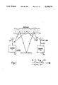
- FIG. 1 is a schematic representation of the invention showing two skywaves
- FIG. 2 is a block diagram of a sounder transmitter
- FIGS. 3A and 3B illustrate the signal format of the sounder transmitter, and FIG. 3C illustrates a complementary sounding code
- FIG. 4 illustrates a sounding signal receiver installation
- FIG. 5 is a block diagram of a synchronous signal detection circuit
- FIG. 6 is a block diagram of a cross-correlation circuit
- FIG. 7 is a schematic representation of the receiver tuning sequence
- FIG. 8 is a block diagram of a received signal level detector
- FIG. 9 is a block diagram of a sounding signal recognition circuit.
- Frequency predictions and planned optimum working frequencies used in conjunction with short-term predictions derived from limited ionospheric soundings do help but the variability of the ionosphere is generally so great and so rapid that this method of frequency selection can still only be used as a guide.
- Real-Time channel sounding on the other hand should provide a relevant solution to this particular problem.
- the second reason for wanting to operate on an optimal working frequency is that even if a randomly chosen frequency can propagate through the ionosphere it will more than likely be totally corrupted by radio interference from other HF users when it arrives at the remote receiver. Choosing the best or optimal working frequency therefore means finding a frequency or frequencies that will not only propagate over long-distant sky-wave paths but will also have relatively low levels of in-band interference at the remote radio receiver.
- FIG. 1 The basic model of a HF sounding system is shown in FIG. 1. This shows two sky-waves S 1 and S 2 propagating between a sounder transmitter 101 and a remote sounder receiver 102. Sky-wave S 1 reaches the receiver after one reflection in the ionosphere while the multipath sky-wave S 2 is reflected twice in the ionosphere and once at the ground. The actual number and type of signals received will depend primarily upon:
- the transmitter sounder 101 has a low power amplifier output connected to a transmitter aerial 104.
- the transmitted signals are received by a 10 m whip aerial 105 connected to the remote sounder receiver 102.
- FIG. 2 is a block diagram of the sounder transmitter.
- a transmit sounder modem 201 produces random frequency and code modulation drives 202 and 203 respectively for a RF synthesiser 204.
- the synthesiser signal is fed to a log-periodic directional antenna 206.
- the transmit frequencies are selected randomly by the modem 201 from the whole HF band from 3 to 30 MHz. Code modulation of each transmitted frequency is then used such that high receiver processing gain can be achieved to enable signals to be received without need for high transmitted power.
- the modulation of the output of the synthesiser 204 is controlled by a modulation control interface 207.
- the modulation control interface 207 Connected to respective inputs 208-210 of the modulation control interface 207 is the code modulation drive 203, a time code modem 211 and a framing 1 kHz tone generator 212.
- the modulation control interface 207 selectably connects the sounder, the time signal or the framing 1 kHz tone to the synthesiser 204 where the frequency hopping output is 90% double side band amplitude modulated (dsb AM).
- dsb AM 90% double side band amplitude modulated
- the sounder transmitter signal hops between pseudo-random frequencies, 301-306 chosen from 550 discrete frequencies distributed between 3.8 MHz and 30 MHz at ten frequency hops per second.
- the 100 ms transit frame 307 includes a first settling interval 308 of 20 ms to allow sufficient time after frequency changing for the synthesisers at both ends of the sounder link to stabilise and also to allow the receiver automatic gain control (AGC) to settle.
- AGC automatic gain control
- the synthesiser output signal is attenuated using raised cosine shaping 309 just prior to and also after changing frequency.
- the modulating code consists of two parts, Code A and Code B, separated by a 12.8 ms interval 310 and transmitted at 10 kb/s. The two halves of the modulating code form a special complementary coded sequence 512 bits long (256+256 bits).
- Coded sounding pulses are pulse compression signals formed from a unique sequence of binary data.
- the binary sequence is designed to have an impulsive auto-correlation function.
- Barker codes are one particular type of digital sequence but these can only be produced for relatively short sequences.
- An example of a complementary code sequence is shown by the signal 311 in FIG. 3C, the first half of the signal being code A and the second half being code B.
- the trace 312 shows the auto-correlation functions of code A ( ⁇ AA) together with code B ( ⁇ BB). This demonstrated that the auto-correlations ⁇ AA and ⁇ BB produce a poor peak (313) to side-lobe (314) ratio, however the side lobes e.g.
- complementary code digital signal For a complementary code digital signal the bit rate must be made high enough to produce a frequency response which is reasonably flat over the bandwidth concerned.
- the length of the code is particularly important because a long sequence will produce a greater processing gain on reception. This improves the detectability of the signal in poor signal to noise conditions and also the selectivity in rejecting any other input signals. Further information on complementary codes is published in "Complementary Series" by M J E Golay, in IRE Transactions on Information Theory, Vol 17-7 pp 82-87, April 1961.
- a 512 bit complementary code was adopted giving a processing gain of 27 dB. This gives a maximum resolution of about 100 ⁇ s at a detection bandwidth of 10 KHz or less.
- time clock modem 211 is described in UK patent application No 8127713. It is controlled by a 1 MHz reference timing clock and produces a pseudo-random binary coded sequence which uniquely encodes the time of day for transmission and enables a similar modem in the remote receiver to achieve timing synchronism within a very small timing error. Accurate timing and stability is essential to achieve and then maintain Synchronism between transmitter and receiver.
- a standard radio receiver 401 operates with an external local oscillator drive from a synthesiser unit 402.
- a 10 m whip antenna 403 connects the signal to the receiver 401.
- the output from the receiver 401 carries a 100 KHz intermediate frequency signal to a system control interface unit 404 where pseudo-synchronous complex amplitude demodulation occurs.
- This produces the appropriate in-phase (real) and quadrature phase (imaginary) detection components for the two cross-correlation units 405, 406.
- the circuit producing the separate detection components is described later with reference to FIG. 5.
- the digitised modulus (see FIG. 6) of the outputs from the cross-correlators 405 and 406 is fed to a central analysis and recording computer 407.
- this data along with time and frequency markers are recorded by a digital tape recorder 408.
- the data can be simultaneously displayed on a printer 407 and can provide output signals for a video display 410 of ionograms and impulse responses for recording by a 16 mm camera 411.
- the receiver includes a time clock modem 412 operated by a 1 MHz reference source to achieve synchronism with the transmitter and for accurate time control by the system control interface 404 of the synthesisor 402 and the cross-correlators 405 and 406.
- a tape reader 413 is provided for program control of the computer 407.
- the demodulation of the signal is done using the synchronous signal detection circuit shown in FIG. 5.
- the 100 kHz IF signal from the output of the receiver 401 is connected to the input 501 of the detection circuit.
- the input 501 is connected via an amplifier 502 to two product detectors 503 and 504 where the 100 kHz IF signal is mixed in phase and in phase quadrature with a 100 kHz signal 505 derived from the If carrier signal.
- the insertion signal 505 is obtained by connecting the 100 kHz If signal via a second amplifier 506 to a band pass (BP) filter 507 which filters out the dsb AM received sounding signal as well as most of the interference.
- BP band pass
- the BP filter 507 has a centre frequency of 100 kHz and a band-width of ⁇ 50 Hz.
- the filtered carrier signal is limited (508) and after further filtering (not shown) is connected to a phase splitter 509.
- the signals at the phase splitter outputs, in phase quadrature, are connected to the respective mixers 503 and 504.
- the product terms in the outputs from the mixers 503 and 504 are then low pass filtered (510, 511) to give two phase-quadratured audio outputs 512 and 513.
- the sounding signal uses conventional double-sideband amplitude modulation. These signals are usually demodulated in a radio receiver using envelope or diode type detectors. Unfortunately although these methods are very simple they only work properly when the signal-to-noise ratio (S/N) is good. To obtain proper demodulation in lower S/N it is important to use synchronous detection. If the frequency stability of the system and the sky-wave radio path was good enough then synchronous detection could be easily done by re-inserting the known carrier frequency in a product detector. True synchronous detection cannot be used in this application however because the end to end frequency stability of the complete system cannot be guaranteed to be less than 4 Hz at all times. This degree of stability is necessary to ensure the accurate operation of the cross-correlators.
- the synchronous signal detection circuit shown in FIG. 5 has a fast response time, normally taking less than 20 ms to correct the phase and frequency of the mixer signals. It can also cope with fading signals provided these are not too deep or the S/N is not too poor.
- a cross correlation circuit shown in FIG. 6 is provided to receive the baseband audio signal from each of the outputs 512, 513 of the detection circuit (FIG. 5).
- the signal at input 601 is sampled by an 8-bit A/D converter 602 controlled by a signal from a 40 kHz clock 603.
- the digitised signal is clocked into a special shift register 604 comprising three series-connected shift register stores 605-607.
- the central shift register 606 acts as a time delay of about 12.8 ms equal to the time separation of the two parts A and B of the complementary coded transmitted signal (FIG. 3).
- the stores 605 and 607 are of such capacity that when code A is completely stored in the register 607, code B is stored in the first register 605.
- the stores 605 and 607 are recirculating stores such that the separate parts A and B can be entirely recirculated, in synchronism, in the respective stores 607 and 605 between successive 40 kHz Clock pulses.
- Parts A and B of the correlation process are stored in the receiver memory stores 608 and 609.
- the output from the shift register code B store 605 and the code B memory store 609 are connected to inputs of a first 8-bit multiplier 610 and similarly the stores 607 and 608 for the transmitted code A and the stored code A are connected to a second multiplier 611.
- the contents of both A and B shift registers are multiplied by the appropriate code sequence after every shift register clock pulse.
- the delay between the two parts of the code has been set at 12.8 ms it could be varied. It is important however that it should exceed the maximum path dispersion. This has been found to be typically 10 ms or less. If the delay were less than this maximum path dispersion then the output signal 617 from the cross-correlator would be corrupted by echo signals of code A arriving at the receiver at the same time as Code B. This would produce "ghost" peaks in the output impulse response.
- FIG. 7 illustrates the timing requirements of the receiver.
- the transmitted signal pulse 701 occupies a 100 ms time frame 702 and the receiver frequency changes 703, 704 take place every 100 ms in synchronism with the frequency changes in the received pulses.
- the correlator output signal is sampled for the presence of a transmitted signal during a 10 ms window 705 centred on the time 706 when the last stage of the code B register should be filled by the first bit of the second part of the coded transmission.
- the window 705 is selected to be less than the guard interval between the two halves A and B of the code.
- the peak signal is measured in this window 705 as described below.
- the mean noise level is measured over the time interval indicated by the line 707.
- the gain of the receiver is continually monitored by measuring the radio receiver automatic gain control (AGC) level in each 100 ms pulse frame. The measurement is made a short time after the frequency change 704 to allow settling of the receiver AGC.
- AGC radio receiver automatic gain control
- the processing of the signal output from the cross-correlators 405, 406 is shown in more detail in FIG. 8.
- the baseband in-phase signal at the output 512 and the quadrature signal at the output 513 from the synchronous signal detector (FIG. 5) are connected to the imputs 801, 802 of the real and imaginary cross-correlators 803, 804.
- the output signals from the correlators representing the complex impulse response are connected to a unit 805 which derives the modulus of the output signals.
- the output signals are connected to respective squaring circuits 806, 807 and the outputs from these circuits are combined in an adder 808 and the square root taken from the sum in the circuit 809.
- the impulse response signal at the output 810 is sampled during the window period 705 by a peak detector 811 and this peak is then converted into a binary number level signal measured in dBs in a level circuit 812.
- the AGC level of the receiver 401 (FIG. 4) is modified by adjustment of the origin and slope of its response curve.
- the receiver AGC signal measured as shown in FIG. 7, is connected to a first input of a difference amplifier 813, the second input voltage being adjustable so as to adjust the zero level for the amplifier.
- the output from the origin adjusting amplifier 813 is connected to a first input of a second difference amplifier 814 with adjustable feedback to the second input so as to adjust the slope of the AGC signal.
- the adjusted AGC signal output from the amplifier 814 is digitised by a 7-bit A/D converter 815.
- the adjustments are made such that the digital output from the A/D converter 815 is a dB ratio referred to 1 ⁇ V.
- This digital output is then added in a binary adder 816 to the measured peak impulse response level (also converted to dBs) to produce the desired output.
- the processing gain of the receiving system will produce an output S/N which is considerably better than the input to it. But the actual output signal level (the peak level of the impulse response) will depend upon the input S/N to the radio receiver. Meanwhile, the receiver AGC level represents the total input signal to the radio which will normally include the sounding signal and/or any noise. This AGC however is used to ensure that the audio output level from the receiver will be constant, irrespective of the input signal-to-noise ratio. It therefore follows that the signal (sounding) level to and out of the cross-correlators will fall as the input signal-to-noise ratio to the radio receiver falls.
- the signal to the correlators will be constant because the AGC is ⁇ captured ⁇ by the sounding signal. Below 10 dB the AGC is affected by signal and noise. At 0 dB the receiver AGC is operating on equal levels of noise and signal so the signal output level will be 3 dB lower. At lower input S/N ratios the signal output level will be proportionally lower.
- the modulus of the impulse response signal at the output 810 from the received signal level detector (FIG. 8) is connected to the input 901 to a multiplexer 902a at the imput of a recirculating shift register store 902 clocked at 10 kHz.
- the impulse response at the input 901 is also connected to a peak detector 903 which measures the peak signal in the time window 705 as did the peak detector 811 in the FIG. 8 arrangement.
- the output from the recirculating store 902 is connected to a calculation unit 904 which computes the mean value of noise in the period 707 (FIG. 7) prior to the peak measurement window 75.
- the outputs from the noise calculation unit and the peak signal detector 903 are 7 bit binary numbers which are compared in a comparator 905 arranged to produce an output binary "1" if S/N ⁇ 8 dB and a "0" otherwise.
- each pulse there will be produced a status "1" or a status "0" depending upon whether that frequency is providing a usable sounding channel.
- a transmission rate of 10 pseudo-random frequency hops per second there will be produced a 10 bps stream of status bits together with signal level and impulse response characteristics relayed back to a communications receiver/transmitter co-located with the sounder transmitter to enable the communications transmitter to optimise the frequencies selected for communicating over the sounding path.
- Scattering functions for each channel can be derived from the received sounding pulses and characteristics for perhaps several hundred frequencies can be accumulated in a minute or so. These characteristics can then be updated at the scanning rate.
- the received signal strength (dB ⁇ V) and mode structure for every tested frequency can be stored to await subsequent interrogation and processing to perhaps decide which frequency or frequencies have the highest probability of propagating a transmitted signal with minimum distortion and with the highest received signal-to-noise ratio.
- Link engineering instructions--other instructions such as crypto input, data speed, message urgency, service being used (e.g. RATT or facsimile) etc.
- An HF channel management system linked to a sounding broadcast station would provide a very powerful ability for automatic control of communications systems from numerous remote stations (mobile air, land and sea) to work into a single control station with high reliability, availability and performance.
- the invention provides the means for real time frequency sounding which can be arranged to automatically tune to the optimum frequency or frequencies.
Applications Claiming Priority (2)
| Application Number | Priority Date | Filing Date | Title |
|---|---|---|---|
| GB8427440 | 1984-10-30 | ||
| GB8427440 | 1984-10-30 |
Publications (1)
| Publication Number | Publication Date |
|---|---|
| US5230076A true US5230076A (en) | 1993-07-20 |
Family
ID=10568986
Family Applications (1)
| Application Number | Title | Priority Date | Filing Date |
|---|---|---|---|
| US06/807,972 Expired - Lifetime US5230076A (en) | 1984-10-30 | 1985-10-29 | Ionospheric sounding |
Country Status (9)
| Country | Link |
|---|---|
| US (1) | US5230076A (sv) |
| AU (1) | AU632279B2 (sv) |
| CA (1) | CA1333921C (sv) |
| DE (1) | DE3546469C2 (sv) |
| FR (1) | FR2714777B1 (sv) |
| GB (1) | GB2253971B (sv) |
| IT (1) | IT1235572B (sv) |
| NL (1) | NL192282C (sv) |
| SE (1) | SE469649B (sv) |
Cited By (40)
| Publication number | Priority date | Publication date | Assignee | Title |
|---|---|---|---|---|
| US5339331A (en) * | 1993-09-09 | 1994-08-16 | Lockheed Corporation | Frequency hopping spread spectrum receiver |
| US5428358A (en) * | 1994-05-03 | 1995-06-27 | The United States Of America As Represented By The Secretary Of The Navy | Apparatus and method for ionospheric mapping |
| US5463656A (en) * | 1993-10-29 | 1995-10-31 | Harris Corporation | System for conducting video communications over satellite communication link with aircraft having physically compact, effectively conformal, phased array antenna |
| US5563918A (en) * | 1993-12-17 | 1996-10-08 | Rockwell International | Method of selecting optimum frequency in skywave communication apparatus |
| US5604503A (en) * | 1995-03-27 | 1997-02-18 | Lockheed Martin Corporation | Multipath and co-channel signal preprocessor |
| WO1997039433A2 (en) * | 1996-04-01 | 1997-10-23 | Tci International, Inc. | Method and apparatus for real-time ionospheric mapping and dynamic forecasting |
| WO2000010282A1 (en) * | 1998-08-10 | 2000-02-24 | Omnipoint Corporation | Synchronization codes for use in communication |
| US6067040A (en) * | 1997-05-30 | 2000-05-23 | The Whitaker Corporation | Low cost-high resolution radar for commercial and industrial applications |
| US6148188A (en) * | 1997-01-17 | 2000-11-14 | Sullivan; William B. | Dynamic Temperature Measurement |
| US6324382B1 (en) * | 1998-10-12 | 2001-11-27 | Agilent Technologies, Inc. | Extraction of primary and co-channel signals |
| US6331997B1 (en) * | 1998-08-04 | 2001-12-18 | Linkair Communication, Inc. | Scheme for spread spectrum multiple access coding |
| GB2365239A (en) * | 2000-07-26 | 2002-02-13 | Alenia Marconi Systems Ltd | Near-vertical incidence skywave HF radar |
| US6356239B1 (en) | 2000-08-23 | 2002-03-12 | The Boeing Company | Method for maintaining instantaneous bandwidth for a segmented, mechanically augmented phased array antenna |
| US20020058478A1 (en) * | 2000-09-28 | 2002-05-16 | De La Chapelle Michael | Return link design for PSD limited mobile satellite communication systems |
| US6400315B1 (en) | 2000-07-20 | 2002-06-04 | The Boeing Company | Control system for electronically scanned phased array antennas with a mechanically steered axis |
| US20020087992A1 (en) * | 2000-08-16 | 2002-07-04 | Bengeult Greg A. | Method and apparatus for bi-directional data services and live television programming to mobile platforms |
| US20030097658A1 (en) * | 2000-08-16 | 2003-05-22 | Richards William R. | Method and apparatus for simultaneous live television and data services using single beam antennas |
| KR20030048722A (ko) * | 2001-12-12 | 2003-06-25 | 박호영 | 전리층 반사파 대역에서의 데이터를 송신하기 전력의 축전방법 |
| US6747960B2 (en) | 2001-12-21 | 2004-06-08 | The Boeing Company | Closed loop power control for TDMA links |
| US20040137840A1 (en) * | 2003-01-15 | 2004-07-15 | La Chapelle Michael De | Bi-directional transponder apparatus and method of operation |
| US20040158863A1 (en) * | 2003-02-10 | 2004-08-12 | Mclain Christopher J. | Method and apparatus for optimizing forward link data rate for radio frequency transmissions to mobile platforms |
| US6847801B2 (en) | 2001-08-30 | 2005-01-25 | The Boeing Company | Communications system and method employing forward satellite links using multiple simultaneous data rates |
| US20050221818A1 (en) * | 2004-03-31 | 2005-10-06 | The Boeing Company | Dynamic configuration management |
| US20060080038A1 (en) * | 2004-10-01 | 2006-04-13 | Deutsches Zentrum Fur Luft- Und Raumfahrt E.V. | Determination of an atmospheric state |
| KR100655210B1 (ko) | 2004-12-06 | 2006-12-08 | 삼성전자주식회사 | 전리층을 이용한 통신 장치 및 방법 |
| US7515916B1 (en) | 2003-09-22 | 2009-04-07 | Veriwave, Incorporated | Method and apparatus for multi-dimensional channel sounding and radio frequency propagation measurements |
| US20090094492A1 (en) * | 2007-10-04 | 2009-04-09 | Veriwave, Inc. | Channel impairment emulator systems and methods |
| US20100034313A1 (en) * | 2008-08-08 | 2010-02-11 | The Boeing Company | System and method for accurate downlink power control of composite qpsk modulated signals |
| WO2015013602A3 (en) * | 2013-07-26 | 2015-03-12 | Massachusetts Institute Of Technology | Accurate timing distribution by high-frequency radio |
| RU2581627C2 (ru) * | 2014-05-21 | 2016-04-20 | Открытое акционерное общество "Омский научно-исследовательский институт приборостроения" (ОАО "ОНИИП") | Лчм-ионозонд |
| US9693330B1 (en) * | 2015-07-30 | 2017-06-27 | Rockwell Collins, Inc. | Wideband high frequency based precision time transfer |
| US9848025B2 (en) * | 2014-12-12 | 2017-12-19 | Services Development Company LLC | Data transmission via a high frequency radio band |
| US9941950B2 (en) | 2014-12-11 | 2018-04-10 | Skywave Networks Llc | Communication method and system that uses low latency/low data bandwidth and high latency/high data bandwidth pathways |
| US20200018841A1 (en) * | 2018-07-12 | 2020-01-16 | Southwest Research Institute | Removal of Directwave High Frequency Signal for Ionospheric Sounder Return Processing |
| US11057103B2 (en) * | 2017-10-03 | 2021-07-06 | Skywave Networks Llc | Method and system of preconditioning transmitted signals |
| EP3701643A4 (en) * | 2017-10-25 | 2021-07-28 | Skywave Networks LLC | FUZZLE LOGIC FOR PROCESSING TRANSMISSION METADATA |
| CN113992287A (zh) * | 2021-10-26 | 2022-01-28 | 封开低频时码授时台 | 一种低频时码授时信号载波频率优选方法及系统 |
| US11309954B2 (en) | 2017-10-04 | 2022-04-19 | Skywave Networks Llc | Technique for selecting the best frequency for transmission based on changing atmospheric conditions |
| US11316596B2 (en) * | 2018-07-26 | 2022-04-26 | Etat Français représenté par le Délégué Général pour L'Armement | Method for detecting at least one compromised computer device in an information system |
| CN114545357A (zh) * | 2022-04-25 | 2022-05-27 | 武汉大学 | 一种基于互谱分析的电离层Es层高分辨率垂直探测方法 |
Families Citing this family (4)
| Publication number | Priority date | Publication date | Assignee | Title |
|---|---|---|---|---|
| ZA842579B (en) * | 1984-04-05 | 1984-11-28 | Gert Nel Janse Van Rensburg | Flow valve |
| JPH0828754B2 (ja) * | 1993-06-30 | 1996-03-21 | 日本電気株式会社 | フレーム同期方式 |
| DE112018004443T5 (de) * | 2017-10-04 | 2020-05-20 | Skywave Networks Llc | Handhabung von signalen, die auf pfaden mit unterschiedlicher anzahl an hops empfangen werden |
| RU2685245C1 (ru) * | 2018-03-19 | 2019-04-17 | Акционерное общество "Научно-производственное предприятие "Полет" | Устройство для анализа и выбора оптимальных авиационных декаметровых радиоканалов с использованием лчм сигналов |
Citations (28)
| Publication number | Priority date | Publication date | Assignee | Title |
|---|---|---|---|---|
| US1761118A (en) * | 1924-11-06 | 1930-06-03 | Rca Corp | Radio signaling system |
| US2191277A (en) * | 1938-09-16 | 1940-02-20 | Rca Corp | Method of and apparatus for making measurements at ultra high frequencies |
| US3020399A (en) * | 1959-01-09 | 1962-02-06 | Rixon Electronics Inc | Reduction of multipath effects by frequency shift |
| US3160813A (en) * | 1959-07-02 | 1964-12-08 | Csf | Tropospheric radio communication system |
| GB1087870A (en) * | 1965-01-25 | 1967-10-18 | Granger Associates | Improved ionosphere radio sounding system |
| US3351859A (en) * | 1964-08-19 | 1967-11-07 | Motorola Inc | Communication system employing multipath rejection means |
| US3443228A (en) * | 1965-11-22 | 1969-05-06 | Gen Atronics Corp | Optimum frequency communication system with different test frequencies in different test intervals |
| US3475684A (en) * | 1965-04-20 | 1969-10-28 | Emi Ltd | Interrogating apparatus for determining optimum frequency for radio communication |
| US3475685A (en) * | 1964-06-13 | 1969-10-28 | Emi Ltd | Interrogating apparatus for determining optimum frequency for radio communication |
| US3532988A (en) * | 1969-01-23 | 1970-10-06 | Motorola Inc | Digital troposcatter multiplex communication system optimum frequency |
| US3617891A (en) * | 1969-05-26 | 1971-11-02 | Emi Electronics Canada | Optimum frequency determining radio communication system |
| US3961172A (en) * | 1973-12-03 | 1976-06-01 | Robert Stewart Hutcheon | Real-time cross-correlation signal processor |
| US4140973A (en) * | 1977-03-29 | 1979-02-20 | Canadian Patents And Development Limited | Channel evaluation apparatus for point-to-point communications systems |
| US4155040A (en) * | 1977-07-27 | 1979-05-15 | Rockwell International Corporation | Frequency programmable RF communications |
| US4197500A (en) * | 1976-11-01 | 1980-04-08 | The United States Of America As Represented By The Secretary Of The Army | Automatic channel selection |
| US4280128A (en) * | 1980-03-24 | 1981-07-21 | The United States Of America As Represented By The Secretary Of The Army | Adaptive steerable null antenna processor |
| US4308617A (en) * | 1977-11-07 | 1981-12-29 | The Bendix Corporation | Noiselike amplitude and phase modulation coding for spread spectrum transmissions |
| US4309773A (en) * | 1980-04-18 | 1982-01-05 | The United States Of America As Represented By The Secretary Of The Navy | Apparatus and method for radio channel selection |
| US4328581A (en) * | 1980-06-20 | 1982-05-04 | Rockwell International Corporation | Adaptive HF communication system |
| US4334322A (en) * | 1979-10-26 | 1982-06-08 | E-Systems, Inc. | Communication management system for providing antijam/privacy capabilities for voice radio communications |
| US4346475A (en) * | 1979-07-13 | 1982-08-24 | U.S. Philips Corporation | Data transmission system operating on the spread spectrum principle |
| US4365347A (en) * | 1980-01-31 | 1982-12-21 | Nippon Electric Co., Ltd. | Channel selecting system for use in a multi-channel mobile communication system |
| US4475215A (en) * | 1982-10-15 | 1984-10-02 | The United States Of America As Represented By The Secretary Of The Army | Pulse interference cancelling system for spread spectrum signals utilizing active coherent detection |
| US4485477A (en) * | 1982-07-19 | 1984-11-27 | Rca Corporation | Fast frequency/code search |
| US4538280A (en) * | 1983-05-05 | 1985-08-27 | E-Systems, Inc. | Coherent spread spectrum pseudonoise tracking loop |
| US4555806A (en) * | 1982-03-27 | 1985-11-26 | Rohde & Schwarz Gmbh & Co. Kg | System for the automatic establishment of a shortwave telegraphy signal connection |
| US4599733A (en) * | 1983-09-19 | 1986-07-08 | The United States Of America As Represented By The Secretary Of The Army | Multilevel noise code mate pair generation and utilization of such codes |
| US4607375A (en) * | 1984-10-17 | 1986-08-19 | Itt Corporation | Covert communication system |
Family Cites Families (4)
| Publication number | Priority date | Publication date | Assignee | Title |
|---|---|---|---|---|
| US3443230A (en) * | 1964-08-03 | 1969-05-06 | Granger Associates | Plural channel oblique ionosphere sounder system |
| FR2461264A1 (fr) * | 1979-07-06 | 1981-01-30 | Commissariat Energie Atomique | Sondeur pour la detection et la mesure de phenomenes relatifs a l'environnement du globe terrestre |
| IL68987A (en) * | 1982-08-03 | 1986-12-31 | Motorola Inc | Method and apparatus for measuring the strength of a radio frequency signal |
| US4744083A (en) * | 1984-09-14 | 1988-05-10 | Geostar Corporation | Satellite-based position determining and message transfer system with monitoring of link quality |
-
1985
- 1985-10-11 GB GB8525105A patent/GB2253971B/en not_active Expired - Lifetime
- 1985-10-17 NL NL8515007A patent/NL192282C/nl not_active IP Right Cessation
- 1985-10-17 DE DE3546469A patent/DE3546469C2/de not_active Expired - Lifetime
- 1985-10-29 CA CA000494055A patent/CA1333921C/en not_active Expired - Fee Related
- 1985-10-29 US US06/807,972 patent/US5230076A/en not_active Expired - Lifetime
- 1985-10-30 AU AU49196/85A patent/AU632279B2/en not_active Expired
-
1986
- 1986-04-24 FR FR8605979A patent/FR2714777B1/fr not_active Expired - Lifetime
- 1986-06-19 IT IT8648153A patent/IT1235572B/it active
- 1986-07-24 SE SE8603211A patent/SE469649B/sv not_active IP Right Cessation
Patent Citations (29)
| Publication number | Priority date | Publication date | Assignee | Title |
|---|---|---|---|---|
| US1761118A (en) * | 1924-11-06 | 1930-06-03 | Rca Corp | Radio signaling system |
| US2191277A (en) * | 1938-09-16 | 1940-02-20 | Rca Corp | Method of and apparatus for making measurements at ultra high frequencies |
| US3020399A (en) * | 1959-01-09 | 1962-02-06 | Rixon Electronics Inc | Reduction of multipath effects by frequency shift |
| US3160813A (en) * | 1959-07-02 | 1964-12-08 | Csf | Tropospheric radio communication system |
| US3475685A (en) * | 1964-06-13 | 1969-10-28 | Emi Ltd | Interrogating apparatus for determining optimum frequency for radio communication |
| US3351859A (en) * | 1964-08-19 | 1967-11-07 | Motorola Inc | Communication system employing multipath rejection means |
| US3495176A (en) * | 1965-01-25 | 1970-02-10 | Granger Associates | Ionosphere sounder system |
| GB1087870A (en) * | 1965-01-25 | 1967-10-18 | Granger Associates | Improved ionosphere radio sounding system |
| US3475684A (en) * | 1965-04-20 | 1969-10-28 | Emi Ltd | Interrogating apparatus for determining optimum frequency for radio communication |
| US3443228A (en) * | 1965-11-22 | 1969-05-06 | Gen Atronics Corp | Optimum frequency communication system with different test frequencies in different test intervals |
| US3532988A (en) * | 1969-01-23 | 1970-10-06 | Motorola Inc | Digital troposcatter multiplex communication system optimum frequency |
| US3617891A (en) * | 1969-05-26 | 1971-11-02 | Emi Electronics Canada | Optimum frequency determining radio communication system |
| US3961172A (en) * | 1973-12-03 | 1976-06-01 | Robert Stewart Hutcheon | Real-time cross-correlation signal processor |
| US4197500A (en) * | 1976-11-01 | 1980-04-08 | The United States Of America As Represented By The Secretary Of The Army | Automatic channel selection |
| US4140973A (en) * | 1977-03-29 | 1979-02-20 | Canadian Patents And Development Limited | Channel evaluation apparatus for point-to-point communications systems |
| US4155040A (en) * | 1977-07-27 | 1979-05-15 | Rockwell International Corporation | Frequency programmable RF communications |
| US4308617A (en) * | 1977-11-07 | 1981-12-29 | The Bendix Corporation | Noiselike amplitude and phase modulation coding for spread spectrum transmissions |
| US4346475A (en) * | 1979-07-13 | 1982-08-24 | U.S. Philips Corporation | Data transmission system operating on the spread spectrum principle |
| US4334322A (en) * | 1979-10-26 | 1982-06-08 | E-Systems, Inc. | Communication management system for providing antijam/privacy capabilities for voice radio communications |
| US4365347A (en) * | 1980-01-31 | 1982-12-21 | Nippon Electric Co., Ltd. | Channel selecting system for use in a multi-channel mobile communication system |
| US4280128A (en) * | 1980-03-24 | 1981-07-21 | The United States Of America As Represented By The Secretary Of The Army | Adaptive steerable null antenna processor |
| US4309773A (en) * | 1980-04-18 | 1982-01-05 | The United States Of America As Represented By The Secretary Of The Navy | Apparatus and method for radio channel selection |
| US4328581A (en) * | 1980-06-20 | 1982-05-04 | Rockwell International Corporation | Adaptive HF communication system |
| US4555806A (en) * | 1982-03-27 | 1985-11-26 | Rohde & Schwarz Gmbh & Co. Kg | System for the automatic establishment of a shortwave telegraphy signal connection |
| US4485477A (en) * | 1982-07-19 | 1984-11-27 | Rca Corporation | Fast frequency/code search |
| US4475215A (en) * | 1982-10-15 | 1984-10-02 | The United States Of America As Represented By The Secretary Of The Army | Pulse interference cancelling system for spread spectrum signals utilizing active coherent detection |
| US4538280A (en) * | 1983-05-05 | 1985-08-27 | E-Systems, Inc. | Coherent spread spectrum pseudonoise tracking loop |
| US4599733A (en) * | 1983-09-19 | 1986-07-08 | The United States Of America As Represented By The Secretary Of The Army | Multilevel noise code mate pair generation and utilization of such codes |
| US4607375A (en) * | 1984-10-17 | 1986-08-19 | Itt Corporation | Covert communication system |
Non-Patent Citations (4)
| Title |
|---|
| "Spread Spectrum Systems" by Robert C. Dixon 2nd Edition 1984. |
| Spread Spectrum Systems by Robert C. Dixon 2nd Edition 1984. * |
| Stremler, Intro. to Communications Systems, pp. 590 596; (Addison Wesley, 1982. * |
| Stremler, Intro. to Communications Systems, pp. 590-596; (Addison-Wesley, 1982. |
Cited By (69)
| Publication number | Priority date | Publication date | Assignee | Title |
|---|---|---|---|---|
| US5339331A (en) * | 1993-09-09 | 1994-08-16 | Lockheed Corporation | Frequency hopping spread spectrum receiver |
| US5463656A (en) * | 1993-10-29 | 1995-10-31 | Harris Corporation | System for conducting video communications over satellite communication link with aircraft having physically compact, effectively conformal, phased array antenna |
| US5563918A (en) * | 1993-12-17 | 1996-10-08 | Rockwell International | Method of selecting optimum frequency in skywave communication apparatus |
| US5428358A (en) * | 1994-05-03 | 1995-06-27 | The United States Of America As Represented By The Secretary Of The Navy | Apparatus and method for ionospheric mapping |
| US5604503A (en) * | 1995-03-27 | 1997-02-18 | Lockheed Martin Corporation | Multipath and co-channel signal preprocessor |
| WO1997039433A3 (en) * | 1996-04-01 | 1997-11-27 | Tci International Inc | Method and apparatus for real-time ionospheric mapping and dynamic forecasting |
| US5943629A (en) * | 1996-04-01 | 1999-08-24 | Tci International, Inc. | Method and apparatus for real-time ionospheric mapping and dynamic forecasting |
| AU712093B2 (en) * | 1996-04-01 | 1999-10-28 | Tci International, Inc. | Method and apparatus for real-time ionospheric mapping and dynamic forecasting |
| WO1997039433A2 (en) * | 1996-04-01 | 1997-10-23 | Tci International, Inc. | Method and apparatus for real-time ionospheric mapping and dynamic forecasting |
| US6148188A (en) * | 1997-01-17 | 2000-11-14 | Sullivan; William B. | Dynamic Temperature Measurement |
| US6067040A (en) * | 1997-05-30 | 2000-05-23 | The Whitaker Corporation | Low cost-high resolution radar for commercial and industrial applications |
| US6331997B1 (en) * | 1998-08-04 | 2001-12-18 | Linkair Communication, Inc. | Scheme for spread spectrum multiple access coding |
| WO2000010282A1 (en) * | 1998-08-10 | 2000-02-24 | Omnipoint Corporation | Synchronization codes for use in communication |
| US6324382B1 (en) * | 1998-10-12 | 2001-11-27 | Agilent Technologies, Inc. | Extraction of primary and co-channel signals |
| US6400315B1 (en) | 2000-07-20 | 2002-06-04 | The Boeing Company | Control system for electronically scanned phased array antennas with a mechanically steered axis |
| GB2365239A (en) * | 2000-07-26 | 2002-02-13 | Alenia Marconi Systems Ltd | Near-vertical incidence skywave HF radar |
| US20030156056A1 (en) * | 2000-07-26 | 2003-08-21 | Perry Kenneth H | Near-vertical incidence hf radar |
| US6831592B2 (en) * | 2000-07-26 | 2004-12-14 | Alenia Marconi Systems Limited | Near-vertical incidence HF radar |
| US7921442B2 (en) | 2000-08-16 | 2011-04-05 | The Boeing Company | Method and apparatus for simultaneous live television and data services using single beam antennas |
| US20020087992A1 (en) * | 2000-08-16 | 2002-07-04 | Bengeult Greg A. | Method and apparatus for bi-directional data services and live television programming to mobile platforms |
| US20030097658A1 (en) * | 2000-08-16 | 2003-05-22 | Richards William R. | Method and apparatus for simultaneous live television and data services using single beam antennas |
| US20090080368A1 (en) * | 2000-08-16 | 2009-03-26 | The Boeing Company | Method and apparatus for bi-directional data services and live television programming to mobile platforms |
| US8646010B2 (en) | 2000-08-16 | 2014-02-04 | The Boeing Company | Method and apparatus for providing bi-directional data services and live television programming to mobile platforms |
| US9055195B2 (en) | 2000-08-16 | 2015-06-09 | The Boeing Company | Method and apparatus for providing bi-directional data services and live television programming to mobile platforms |
| US6356239B1 (en) | 2000-08-23 | 2002-03-12 | The Boeing Company | Method for maintaining instantaneous bandwidth for a segmented, mechanically augmented phased array antenna |
| US7054593B2 (en) | 2000-09-28 | 2006-05-30 | The Boeing Company | Return link design for PSD limited mobile satellite communication systems |
| US20070026795A1 (en) * | 2000-09-28 | 2007-02-01 | De La Chapelle Michael | Return link design for psd limited mobile satellite communication systems |
| US7630683B2 (en) | 2000-09-28 | 2009-12-08 | The Boeing Company | Return link design for PSD limited mobile satellite communication systems |
| US20020058478A1 (en) * | 2000-09-28 | 2002-05-16 | De La Chapelle Michael | Return link design for PSD limited mobile satellite communication systems |
| US7136621B2 (en) | 2000-09-28 | 2006-11-14 | The Boeing Company | Return link design for PSD limited mobile satellite communication systems |
| US20050070222A1 (en) * | 2001-08-30 | 2005-03-31 | Chapelle Michael De La | Communications system and method employing forward satellite links using multiple simultaneous data rates |
| US7120389B2 (en) | 2001-08-30 | 2006-10-10 | The Boeing Company | Communications system and method employing forward satellite links using multiple simultaneous data rates |
| US6847801B2 (en) | 2001-08-30 | 2005-01-25 | The Boeing Company | Communications system and method employing forward satellite links using multiple simultaneous data rates |
| KR20030048722A (ko) * | 2001-12-12 | 2003-06-25 | 박호영 | 전리층 반사파 대역에서의 데이터를 송신하기 전력의 축전방법 |
| US6747960B2 (en) | 2001-12-21 | 2004-06-08 | The Boeing Company | Closed loop power control for TDMA links |
| US20040137840A1 (en) * | 2003-01-15 | 2004-07-15 | La Chapelle Michael De | Bi-directional transponder apparatus and method of operation |
| US7751337B2 (en) | 2003-02-10 | 2010-07-06 | The Boeing Company | Method and apparatus for optimizing forward link data rate for radio frequency transmissions to mobile platforms |
| US20040158863A1 (en) * | 2003-02-10 | 2004-08-12 | Mclain Christopher J. | Method and apparatus for optimizing forward link data rate for radio frequency transmissions to mobile platforms |
| US7515916B1 (en) | 2003-09-22 | 2009-04-07 | Veriwave, Incorporated | Method and apparatus for multi-dimensional channel sounding and radio frequency propagation measurements |
| US20050221818A1 (en) * | 2004-03-31 | 2005-10-06 | The Boeing Company | Dynamic configuration management |
| US7860497B2 (en) | 2004-03-31 | 2010-12-28 | The Boeing Company | Dynamic configuration management |
| US7502689B2 (en) * | 2004-10-01 | 2009-03-10 | Deutsches Zentrum für Luft—und Raumfahrt e.V. | Determination of an atmospheric state |
| US20060080038A1 (en) * | 2004-10-01 | 2006-04-13 | Deutsches Zentrum Fur Luft- Und Raumfahrt E.V. | Determination of an atmospheric state |
| KR100655210B1 (ko) | 2004-12-06 | 2006-12-08 | 삼성전자주식회사 | 전리층을 이용한 통신 장치 및 방법 |
| US7890821B2 (en) | 2007-10-04 | 2011-02-15 | Veriwave, Inc. | Channel impairment emulator systems and methods |
| US20090094492A1 (en) * | 2007-10-04 | 2009-04-09 | Veriwave, Inc. | Channel impairment emulator systems and methods |
| US8189708B2 (en) | 2008-08-08 | 2012-05-29 | The Boeing Company | System and method for accurate downlink power control of composite QPSK modulated signals |
| US20100034313A1 (en) * | 2008-08-08 | 2010-02-11 | The Boeing Company | System and method for accurate downlink power control of composite qpsk modulated signals |
| US10148345B2 (en) | 2013-07-26 | 2018-12-04 | Massachusetts Institute Of Technology | Accurate timing distribution by high-frequency radio |
| WO2015013602A3 (en) * | 2013-07-26 | 2015-03-12 | Massachusetts Institute Of Technology | Accurate timing distribution by high-frequency radio |
| RU2581627C2 (ru) * | 2014-05-21 | 2016-04-20 | Открытое акционерное общество "Омский научно-исследовательский институт приборостроения" (ОАО "ОНИИП") | Лчм-ионозонд |
| US11581940B2 (en) | 2014-12-11 | 2023-02-14 | Skywave Networks Llc | Communication method and system that uses low latency/low data bandwidth and high latency/high data bandwidth pathways |
| US9941950B2 (en) | 2014-12-11 | 2018-04-10 | Skywave Networks Llc | Communication method and system that uses low latency/low data bandwidth and high latency/high data bandwidth pathways |
| US10778323B2 (en) | 2014-12-11 | 2020-09-15 | Skywave Networks Llc | Communication method and system that uses low latency/low data bandwidth and high latency/high data bandwidth pathways |
| US9848025B2 (en) * | 2014-12-12 | 2017-12-19 | Services Development Company LLC | Data transmission via a high frequency radio band |
| US9693330B1 (en) * | 2015-07-30 | 2017-06-27 | Rockwell Collins, Inc. | Wideband high frequency based precision time transfer |
| US11575430B2 (en) * | 2017-10-03 | 2023-02-07 | Skywave Networks Llc | Method and system of preconditioning transmitted signals |
| US11057103B2 (en) * | 2017-10-03 | 2021-07-06 | Skywave Networks Llc | Method and system of preconditioning transmitted signals |
| US20220182136A1 (en) * | 2017-10-03 | 2022-06-09 | Skywave Networks Llc | Method and system of preconditioning transmitted signals |
| US11309954B2 (en) | 2017-10-04 | 2022-04-19 | Skywave Networks Llc | Technique for selecting the best frequency for transmission based on changing atmospheric conditions |
| EP3701643A4 (en) * | 2017-10-25 | 2021-07-28 | Skywave Networks LLC | FUZZLE LOGIC FOR PROCESSING TRANSMISSION METADATA |
| GB2581931B (en) * | 2017-10-25 | 2022-10-12 | Skywave Networks Llc | Fuzzy logic for processing transmission meta data |
| US11496211B2 (en) | 2017-10-25 | 2022-11-08 | Skywave Networks Llc | Fuzzy logic for processing transmission meta data |
| US11047967B2 (en) * | 2018-07-12 | 2021-06-29 | Southwest Research Institute | Removal of directwave high frequency signal for ionospheric sounder return processing |
| US20200018841A1 (en) * | 2018-07-12 | 2020-01-16 | Southwest Research Institute | Removal of Directwave High Frequency Signal for Ionospheric Sounder Return Processing |
| US11316596B2 (en) * | 2018-07-26 | 2022-04-26 | Etat Français représenté par le Délégué Général pour L'Armement | Method for detecting at least one compromised computer device in an information system |
| CN113992287A (zh) * | 2021-10-26 | 2022-01-28 | 封开低频时码授时台 | 一种低频时码授时信号载波频率优选方法及系统 |
| CN114545357A (zh) * | 2022-04-25 | 2022-05-27 | 武汉大学 | 一种基于互谱分析的电离层Es层高分辨率垂直探测方法 |
| CN114545357B (zh) * | 2022-04-25 | 2022-07-19 | 武汉大学 | 一种基于互谱分析的电离层Es层高分辨率垂直探测方法 |
Also Published As
| Publication number | Publication date |
|---|---|
| NL192282C (nl) | 1997-04-03 |
| IT8648153A0 (it) | 1986-06-19 |
| DE3546469A1 (de) | 1993-07-29 |
| FR2714777B1 (fr) | 1996-04-26 |
| SE8603211D0 (sv) | 1986-07-24 |
| SE469649B (sv) | 1993-08-09 |
| GB2253971B (en) | 1993-02-03 |
| DE3546469C2 (de) | 1994-09-08 |
| NL8515007A (nl) | 1992-10-01 |
| CA1333921C (en) | 1995-01-10 |
| FR2714777A1 (fr) | 1995-07-07 |
| NL192282B (nl) | 1996-12-02 |
| GB2253971A (en) | 1992-09-23 |
| AU632279B2 (en) | 1992-12-24 |
| SE8603211L (sv) | 1992-11-06 |
| IT1235572B (it) | 1992-09-11 |
Similar Documents
| Publication | Publication Date | Title |
|---|---|---|
| US5230076A (en) | Ionospheric sounding | |
| Maslin | HF communications: a systems approach | |
| US5719579A (en) | Virtual noise radar waveform for reduced radar detectability | |
| US4653068A (en) | Frequency hopping data communication system | |
| US3980945A (en) | Digital communications system with immunity to frequency selective fading | |
| US5412620A (en) | Hydroacoustic communications system robust to multipath | |
| US6486827B2 (en) | Sparse frequency waveform radar system and method | |
| US4408322A (en) | Method and apparatus for measuring signal to noise ratio in a TDMA communications system | |
| US3761813A (en) | Method of telecommunication via satellite and systems using this method | |
| US5109231A (en) | Radar arrangement | |
| RU2572083C1 (ru) | Способ и устройство (варианты) создания преднамеренных помех | |
| Bergadà et al. | Polarization diversity in a long-haul transequatorial HF link from Antarctica to Spain | |
| US4617570A (en) | Interference cancelling receiver having high angular resolution intercept of transmitted radiators | |
| Hansen et al. | Adaptive array for elimination of multipath interference at HF | |
| Prediger et al. | Propagation measurements at 60 GHz in railroad tunnels | |
| RU2779925C1 (ru) | Способ разнесенного приема сигнала, переданного по многолучевому каналу, и система для его осуществления | |
| Berktay et al. | Communications aspects of underwater telemetry | |
| KR101832910B1 (ko) | 필터 배열 방식의 위성신호 검출 장치 | |
| Bergadà Caramés et al. | Polarization diversity in a long-haul transequatorial HF link from Antarctica to Spain | |
| Staniforth | A study of interference in the HF aeronautical bands | |
| Poberezhskiy | Diversity Schemes and Coherent Combining in Digital Receivers | |
| Mozzone et al. | Long range, large throughput radio data links for DUSS (Deployable Underwater Surveillance Systems) | |
| GB2104348A (en) | Improvements in or relating to radio communication data systems | |
| RU2520401C2 (ru) | Способ повышения скрытности радиоизлучающего средства в радиолинии с ппрч | |
| Aarons | General concepts of modern HF communications |
Legal Events
| Date | Code | Title | Description |
|---|---|---|---|
| AS | Assignment |
Owner name: SECRETARY OF STATE FOR DEFENCE IN HER BRITANNIC MA Free format text: ASSIGNMENT OF ASSIGNORS INTEREST.;ASSIGNOR:WILKINSON, ROBERT G.;REEL/FRAME:004506/0442 Effective date: 19851011 |
|
| STCF | Information on status: patent grant |
Free format text: PATENTED CASE |
|
| FEPP | Fee payment procedure |
Free format text: PAYOR NUMBER ASSIGNED (ORIGINAL EVENT CODE: ASPN); ENTITY STATUS OF PATENT OWNER: LARGE ENTITY |
|
| FPAY | Fee payment |
Year of fee payment: 4 |
|
| FPAY | Fee payment |
Year of fee payment: 8 |
|
| AS | Assignment |
Owner name: QINETIQ LIMITED, UNITED KINGDOM Free format text: ASSIGNMENT OF ASSIGNORS INTEREST;ASSIGNOR:SECRETARY OF STATE FOR DEFENCE, THE;REEL/FRAME:012831/0459 Effective date: 20011211 |
|
| FPAY | Fee payment |
Year of fee payment: 12 |
|
| AS | Assignment |
Owner name: VOCALCOMM GROUP, LLC, DELAWARE Free format text: ASSIGNMENT OF ASSIGNORS INTEREST;ASSIGNOR:QINETIQ LIMITED COMPANY NO. 3796233;REEL/FRAME:019714/0042 Effective date: 20070215 Owner name: VOCALCOMM GROUP, LLC,DELAWARE Free format text: ASSIGNMENT OF ASSIGNORS INTEREST;ASSIGNOR:QINETIQ LIMITED COMPANY NO. 3796233;REEL/FRAME:019714/0042 Effective date: 20070215 |
|
| FEPP | Fee payment procedure |
Free format text: PAYER NUMBER DE-ASSIGNED (ORIGINAL EVENT CODE: RMPN); ENTITY STATUS OF PATENT OWNER: LARGE ENTITY Free format text: PAYOR NUMBER ASSIGNED (ORIGINAL EVENT CODE: ASPN); ENTITY STATUS OF PATENT OWNER: LARGE ENTITY |