US5223689A - Profiles to insure proper heating function - Google Patents
Profiles to insure proper heating function Download PDFInfo
- Publication number
- US5223689A US5223689A US07/692,987 US69298791A US5223689A US 5223689 A US5223689 A US 5223689A US 69298791 A US69298791 A US 69298791A US 5223689 A US5223689 A US 5223689A
- Authority
- US
- United States
- Prior art keywords
- function
- power
- peak
- net power
- determining
- Prior art date
- Legal status (The legal status is an assumption and is not a legal conclusion. Google has not performed a legal analysis and makes no representation as to the accuracy of the status listed.)
- Expired - Lifetime
Links
Images


Classifications
-
- B—PERFORMING OPERATIONS; TRANSPORTING
- B23—MACHINE TOOLS; METAL-WORKING NOT OTHERWISE PROVIDED FOR
- B23K—SOLDERING OR UNSOLDERING; WELDING; CLADDING OR PLATING BY SOLDERING OR WELDING; CUTTING BY APPLYING HEAT LOCALLY, e.g. FLAME CUTTING; WORKING BY LASER BEAM
- B23K1/00—Soldering, e.g. brazing, or unsoldering
-
- B—PERFORMING OPERATIONS; TRANSPORTING
- B23—MACHINE TOOLS; METAL-WORKING NOT OTHERWISE PROVIDED FOR
- B23K—SOLDERING OR UNSOLDERING; WELDING; CLADDING OR PLATING BY SOLDERING OR WELDING; CUTTING BY APPLYING HEAT LOCALLY, e.g. FLAME CUTTING; WORKING BY LASER BEAM
- B23K3/00—Tools, devices or special appurtenances for soldering, e.g. brazing, or unsoldering, not specially adapted for particular methods
- B23K3/02—Soldering irons; Bits
- B23K3/03—Soldering irons; Bits electrically heated
- B23K3/033—Soldering irons; Bits electrically heated comprising means for controlling or selecting the temperature or power
Definitions
- the present invention relates to the use, during a heating operation, of a power measurement to determine when a heating operation has been properly completed, and more particularly to predetermining various parameters of a heating system such that by measuring peak power delivered by an electric heater, relative to some other parameter of the system, the proper completion of a heating operation is determinable.
- the present invention is applicable to many different types of heating functions, from industrial heating of metals or the like, to food preparation, soldering irons and the like. In many repetitive operations, it is desirable to insure repeatability without concentrated operator attention.
- Cold solder joints have been a major source of problems in electrical and electronic systems since the inception of this industry.
- the problem with cold solder joints has been greatly increased with the advent of chips, since overheating to insure against a cold solder joint may very well damage or destroy expensive and delicate chips.
- a technician or operator particularly one in a high production environment, is often walking a tightrope between underheating and overheating during a soldering operation, both conditions resulting in a defective component or board, some of these boards costing more than one thousand dollars.
- peak power achieved within a specified length of time indicates that the connection has achieved proper temperature to provide a good solder joint.
- a fundamental function is determined, time.
- the architecture of a board or the like is studied, as well as the physical tolerance to temperature of the components on the board, to determine the maximum safe exposure of various elements to elevated temperatures for the said specified period of time.
- the temperatures to which an element is exposed vary depending upon location of the elements relative to the source of heat; the soldering iron tip shape and wattage; iron temperature; and the rate of transfer of heat to the junction to be soldered.
- the next parameter is the heat required to be transferred to provide a proper solder joint, a function of the fusion temperature of the solder and the rate of dissipation of heat from the whole complex.
- the peak power required to achieve the desired temperature to provide a proper joint without damage is determined. Thereafter, the operator must only listen for or look for a signal or display indicating that such peak power and fall-off curve have been achieved.
- the overall configuration of a power versus time curve including the ramp-up and ramp-down regions of the curve, is chosen as determinative of a proper solder joint.
- Power is supplied to a heater in contact with a connection to be soldered. The flow of solder is observed, and when it is determined that the connection is properly heated and melted, the plot of power versus time is noted. This plot now serves as a characteristic "print" of a completed joint.
- the heater employed in this operation must have low thermal inertia and must be essentially isolated from heat sinks or other heat sources.
- the thermal inertia of the heater must be far less than the items to be heated. Coupling from a source of current to the heater is preferably inductive to further reduce thermal inertia.
- soldering iron described in Pat. No. 4,256,945 may also be employed.
- the descriptions of these two patents, relative to the operation of the heater, are incorporated herein by reference.
- Other self-regulating heaters may also be employed.
- the curves developed herein are typical of soldering functions. Other heating systems will have different curves, but curves can be developed for each system and employed as stated herein.
- the term "effective Curie temperature” is the temperature at which a material becomes for purposes of this invention essentially paramagnetic. Such temperature may be as little as 1° C. or as much as 100° C. less than absolute Curie temperature depending upon the material employed.
- Yet another object of the present invention is to provide automatic, inspectionless heating with record generation.
- FIGS. 1A and 1B are graphs of a proper net power versus relationship
- FIG. 2 is a graph depicting effect of load size on the power/connection temperature curve
- FIG. 3 sets forth in graph form the results of a solder pot load test on three different cartridges of the same wattage
- FIG. 4 illustrates a solder pot
- FIG. 5 is a block diagram of a soldering iron control system based on the present invention.
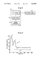
- FIG. 6 is a graph which illustrates a satisfactory curves of a soldering in accordance with a second embodiment of the present invention.
- FIGS. 7 and 8 are graphs illustrating unsatisfactory curves of a soldering operation.
- FIG. 9 is a block diagram of a circuit for automatically detecting satisfactory and unsatisfactory operations.
- a quality solder connection that does not damage the devices or products being soldered, is a connection that has been increased in temperature to 450°-500° F. in not more than five seconds.
- the 450°-500° F. connection temperature must be maintained for 0.5 second.
- the tip surface has been properly tinned and maintained.
- Heat is initially delivered to a solder connection based on the temperature differential between the tip and the solder connection.
- the temperature of the tip decreases as the solder connection temperature increases.
- the minimum heater temperature is achieved, the power will be at a maximum.
- the connection temperature is dependent upon the heater temperature at this phase in the cycle of operation, because of steady state heat transfer.
- the power curves all have the same basic shape. Initially, the power curve is a horizontal line, representing constant power. The power then increases, reaches a peak, and declines to some level between a peak and the horizontal line. This characteristic curve occurs when the same tip cartridge is used with different thermal loads as in FIGS. 1. It also occurs when different tip cartridges are used with the same thermal load as in FIG. 2. We can use this power curve to predict the proper temperature of a solder connection.
- the first region is termed STORED HEAT.
- STORED HEAT The first region is termed STORED HEAT.
- This phase occurs rapidly, definitely complete in less than a second. Temperature control of the solder connection is not possible in this region because the heater has not responded to the thermal load. Since it is desired to have the heater respond to the load, Region 1 should be minimized by reducing the thermal inertia of the tip.
- TRANSIENT HEATING starts once the heater temperature decreases in response to the thermal load.
- connection temperature increases rapidly to a peak and the connection temperature continues to increase, though slower than in the first region. Heat is supplied to the connection by the heater, as well as some contribution from stored energy, due to the tip temperature's further decline. Temperature control of the solder connection is improved, because a portion of the heat is provided by the heater, but still requires operator judgment.
- the third region, STEADY STATE HEATING, is the most interesting because the connection temperature can be predicted from the net power. During this phase, the net power is decreasing as the connection temperature increases. The connection temperature continues to increase but slowly. Heat is supplied to the connection from the heater and not through the stored heat of the tip.
- connection temperature Since the connection temperature increase obeys the laws of steady state heat transfer, the connection temperature is related to the power in the following manner:
- a temperature self-regulating heater such as disclosed in U.S. Pat. Nos. 4,256,965, 4,745,264 and others of the same general characteristics, and particularly those assigned to the same assignee as the present invention, the lowering of temperature during Region 1 causes the temperature of the ferromagnetic material to fall below effective Curie temperature, so that increasing power is supplied to the heater.
- FIG. 1B shows the effect of load size on the power/connection temperature curve.
- increasing the load increases the peak power and decreases the peak power temperature.
- Solder connections formed on the heavy and medium load were not quality connections. In neither instance was the desired temperature range achieved during the ten second test.
- the light load also did not produce a quality connection, since the peak power occurred after the desired temperature had been reached, indicating an over-powered iron that raises temperature beyond safe limits. Region 3 heating did not occur while the connection temperature was between 450°-500° F.
- the thermal load, or solder connection is the same, but the configuration of the tip is different.
- This figure shows that a larger and/or shorter tip (curve -013), increases peak power and increases the peak power temperature. Only the connection formed by the curve designed -013 could be considered a quality connection.
- the connection temperature of 450° F. occurred in Region 3 and just beyond the peak power. The other two connections were unacceptable.
- the connection represented by curve -002 never achieved a 450° F. temperature, and the connection represented by curve -037 took too long, ten seconds, to achieve the minimum temperature. All three curves were created with 35 watt heaters and were taken over the same time interval, ten seconds, as indicated already.
- a solder pot see FIG. 4, which represents an infinite load, is employed in the tests illustrated in FIG. 3, and comprises a temperature-controlled container with solder. Tests were conducted by placing the soldering iron tip in the molten solder and allowing the solder temperature to cool slowly. The solder pot load test allows characterization of the power of a cartridge when its tip, is at different temperatures (T L ). The solder pot test allows one to predict the desired peak powers required for quality solder connections using different tip configurations. The output power versus temperature variation is due to the thermal resistance of the tip.
- FIG. 3 shows the results of the solder pot load test for three different cartridges of the same wattage, but different tip configurations. Since this is also steady state heat transfer, the output power indicates the connection temperature and the formation of a quality solder connection. Again, a quality connection is formed at a temperature between 450°-500° F. For the 037 cartridge, the output power corresponding to this temperature range is 11.5 to 9.5 watts. When using an 013 tip cartridge the desired power, of 9.5 to 11.5 watts could not be achieved. If the peak power exceeds 11.5 watts, a quality connection has been performed only if the power decreases to 11.5 in less than five seconds.
- a soldering iron 10 designated in the drawing as an instrument handle, is provided with r.f. power by an RFG-30 power supply 12, which includes a power sensor 14. Sensor 14 senses the power supplied to iron 10, and provides a d.c. signal to a peak power indicator 16. When proper peak power is indicated within the five-second window, the solder connection has been completed and the operation is to be terminated. Termination may be by the operator, or in a fully automated system, by the equipment. The power to the heater is to be maintained for a period after peak power is reached. Thus, in an automated system, the peak power meter has a delay before shut-off which depends upon the system configuration. It has been found that, in most instances, a half-second delay is sufficient, but an adjustment is provided to permit the delay to be varied.
- the heater employed in the present invention must have a temperature control mechanism which prevents a temperature rise above a predetermined temperature, and it must be operated in conjunction with a net power meter. When these constraints are observed, the concepts of the present invention are applicable.
- the temperature regulation in accordance with the patents cited above, is by Curie point control; wherein when a heater is near its effective Curie temperature, it is idling, but as soon as its temperature falls, produces increasing heat energy.
- Peak power indicator 16 may be a bell, a whistle, an oscilloscope for displaying the net power versus temperature curve occurring over the five-second interval, a chart recorder, or a computer that analyzes the function and provides a print-out, whereby a permanent record of each operation is available.
- the time of the heating operation is fixed, and the net power versus temperature curve is plotted. Specifically, the net power is observed throughout the five-second window, and, if a power variation as illustrated in FIG. 1 is achieved, a quality solder joint is achieved.
- a net power versus time profile is employed.
- the heater is a self-regulating type of low thermal inertia relative to the load.
- temperature is measured only during calibration of the system, but not during actual operation.
- the heater size and available range must be matched to the load.
- the quantity of solder can be employed to optimize temperature exchange in the heater, to improve response time.
- a profile is illustrated for a situation where a wire is soldered to a connection.
- the heater power rises within a specified time to maximum at point X, at which time, the Curie temperature is reached and the power being delivered to the load falls off to a low point, X'.
- a second peak, point Y which must also occur within a specified time, results from the solder melting, spreading out, wetting the heater and transferring heat from the heater to the connection, which reduces the heater temperature thus drawing power up to point Y.
- the heater Once again self regulates but now the thermal load is greater, thus the net power required to maintain the self-regulation temperature is higher. If, as in FIG. 6, the idle power is above, no load line Z', the connection has been completed properly. If as in FIG. 7 the idle power is below line Z' the connection has not been made.
- the curve illustrates a bad solder connection.
- the power curve rises to peak power at X but second peak Y is missing, indicating that solder has not been melted. This failure indicates that no solder is present or the solder has not wetted the heater.
- the line Z falls to about the no-load line, indicating little or no heat transfer to the load indicating the heater is not thermally in contact with the load (wire).
- the curve illustrates a condition where points X and Y are obtained but the power falls to a level below the proper termination steady state load line, indicating no member was connected, such as a wire, or little if any wetting by the solder to the members to be soldered occurred.
- net power is employed herein to indicate the power actually delivered to the load.
- the power supply employed in these tests is a constant current supply operating at 13.56 MHz.
- a directional coupler was employed to determine net power, and in the time tests, a chart recorder was employed.
- a plot of a chart recorder or the like may be employed to observe operation.
- automatic operation may be achieved by measuring the two peaks X and Y, and the amplitude of the Z region.
- FIG. 9 Such a system is illustrated in FIG. 9.
- a first peak detector-timer 22 receives an input from lead 23 indicating net power delivered to the load.
- a net power meter may be employed for this purpose.
- a timer is triggered and if the net power does not rise to the level X of FIG. 6 within a specified time, say three seconds, a failure signal is applied to a lead 24. If the peak is reached within the specified time a signal appears on lead 26 and enables a second peak detector 28 to receive the input signal on lead 23 and starts its timer. If the second peak is reached within about four seconds after enablement of the timer of the second detector 28, an enable signal appears on lead 30. If the peak is not reached within the specified time signal again appears on lead 24.
- a signal does appear on lead 30, the timer of a range detector 32 is enabled and the detector 32 receives the input signal. If the input signal falls to within a range specified by the range detector, a level as approximated by the load line Z' within the specified time, about five seconds after enablement, then a signal appears on "completed" lead 34, otherwise the signal appears on the failure lead 24. If the signal does appear on lead 34 it is employed over lead 36 to reset the system. The signal on lead 24 may be employed to sound an alarm or provide some other indication of failure.
Landscapes
- Engineering & Computer Science (AREA)
- Mechanical Engineering (AREA)
- Electric Connection Of Electric Components To Printed Circuits (AREA)
Abstract
Description
(heater temperature-connection temperature)=net power×thermal resistance
Claims (25)
Priority Applications (1)
| Application Number | Priority Date | Filing Date | Title |
|---|---|---|---|
| US07/692,987 US5223689A (en) | 1989-06-13 | 1991-04-29 | Profiles to insure proper heating function |
Applications Claiming Priority (2)
| Application Number | Priority Date | Filing Date | Title |
|---|---|---|---|
| US36530089A | 1989-06-13 | 1989-06-13 | |
| US07/692,987 US5223689A (en) | 1989-06-13 | 1991-04-29 | Profiles to insure proper heating function |
Related Parent Applications (1)
| Application Number | Title | Priority Date | Filing Date |
|---|---|---|---|
| US36530089A Continuation-In-Part | 1989-06-13 | 1989-06-13 |
Publications (1)
| Publication Number | Publication Date |
|---|---|
| US5223689A true US5223689A (en) | 1993-06-29 |
Family
ID=27002859
Family Applications (1)
| Application Number | Title | Priority Date | Filing Date |
|---|---|---|---|
| US07/692,987 Expired - Lifetime US5223689A (en) | 1989-06-13 | 1991-04-29 | Profiles to insure proper heating function |
Country Status (1)
| Country | Link |
|---|---|
| US (1) | US5223689A (en) |
Cited By (13)
| Publication number | Priority date | Publication date | Assignee | Title |
|---|---|---|---|---|
| US5480398A (en) * | 1992-05-01 | 1996-01-02 | Hemostatic Surgery Corporation | Endoscopic instrument with disposable auto-regulating heater |
| US5480397A (en) * | 1992-05-01 | 1996-01-02 | Hemostatic Surgery Corporation | Surgical instrument with auto-regulating heater and method of using same |
| US5485392A (en) * | 1994-09-12 | 1996-01-16 | The United States Of America As Represented By The Secretary Of The Navy | Manual soldering process monitoring system |
| US5496314A (en) * | 1992-05-01 | 1996-03-05 | Hemostatic Surgery Corporation | Irrigation and shroud arrangement for electrically powered endoscopic probes |
| US5593406A (en) * | 1992-05-01 | 1997-01-14 | Hemostatic Surgery Corporation | Endoscopic instrument with auto-regulating heater and method of using same |
| US5611798A (en) * | 1995-03-02 | 1997-03-18 | Eggers; Philip E. | Resistively heated cutting and coagulating surgical instrument |
| US20060025209A1 (en) * | 1996-12-30 | 2006-02-02 | Walker Jay S | Method and handheld apparatus for facilitating remote play of a slot machine |
| US20060197862A1 (en) * | 2005-03-02 | 2006-09-07 | Premier Image Technology Corporation | Camera module and the manufacturing process thereof |
| CN105328292A (en) * | 2014-08-04 | 2016-02-17 | 特拉华资本构造公司 | Soldering iron with automatic soldering verification |
| EP3115142A1 (en) * | 2015-07-08 | 2017-01-11 | OK International, Inc. | An intelligent soldering cartridge for automatic soldering connection validation |
| US20200016674A1 (en) * | 2018-07-10 | 2020-01-16 | Hakko Corporation | Composite Soldering, De-Soldering Station Load Detection |
| US10688578B2 (en) | 2014-08-04 | 2020-06-23 | OK International, Inc | Variable temperature controlled soldering iron |
| US10716220B2 (en) | 2014-08-04 | 2020-07-14 | Ok International, Inc. | Variable temperature controlled soldering iron |
Citations (13)
| Publication number | Priority date | Publication date | Assignee | Title |
|---|---|---|---|---|
| US3991297A (en) * | 1975-02-27 | 1976-11-09 | Bell Telephone Laboratories, Incorporated | Electrically heated soldering device |
| US4224744A (en) * | 1978-05-12 | 1980-09-30 | Pace Incorporated | Circuitry for teaching soldering and practice circuit board for use therewith |
| US4256945A (en) * | 1979-08-31 | 1981-03-17 | Iris Associates | Alternating current electrically resistive heating element having intrinsic temperature control |
| US4317980A (en) * | 1980-01-02 | 1982-03-02 | International Business Machines Corporation | Resistance welding sequence cycle control |
| US4390954A (en) * | 1981-04-13 | 1983-06-28 | Merrick Engineering, Inc. | Override control apparatus and method for parameter adjustment of digitally based welding process programmers |
| US4580026A (en) * | 1985-06-05 | 1986-04-01 | Westinghouse Electric Corp. | Method and apparatus for controlling the temperature of continuously fed wires |
| US4595816A (en) * | 1984-08-31 | 1986-06-17 | Westinghouse Electric Corp. | Automated soldering process and apparatus |
| US4698774A (en) * | 1984-10-02 | 1987-10-06 | Kabushiki Kaisha Tamura Seisakusho | Method of and apparatus for controlling automatic soldering system |
| US4720623A (en) * | 1986-05-01 | 1988-01-19 | E. I. Du Pont De Nemours And Company | Power control device for a resistance heater in an oven |
| US4795886A (en) * | 1986-12-19 | 1989-01-03 | Metcal, Inc. | Temperature control in which the control parameter is the degree of imperfection in the impedance matching |
| US4814587A (en) * | 1986-06-10 | 1989-03-21 | Metcal, Inc. | High power self-regulating heater |
| US4839501A (en) * | 1984-12-21 | 1989-06-13 | Metcal, Inc. | Cartridge soldering iron |
| JPH06245469A (en) * | 1993-02-23 | 1994-09-02 | Shinano Kenshi Kk | Rotor of stepping motor |
-
1991
- 1991-04-29 US US07/692,987 patent/US5223689A/en not_active Expired - Lifetime
Patent Citations (13)
| Publication number | Priority date | Publication date | Assignee | Title |
|---|---|---|---|---|
| US3991297A (en) * | 1975-02-27 | 1976-11-09 | Bell Telephone Laboratories, Incorporated | Electrically heated soldering device |
| US4224744A (en) * | 1978-05-12 | 1980-09-30 | Pace Incorporated | Circuitry for teaching soldering and practice circuit board for use therewith |
| US4256945A (en) * | 1979-08-31 | 1981-03-17 | Iris Associates | Alternating current electrically resistive heating element having intrinsic temperature control |
| US4317980A (en) * | 1980-01-02 | 1982-03-02 | International Business Machines Corporation | Resistance welding sequence cycle control |
| US4390954A (en) * | 1981-04-13 | 1983-06-28 | Merrick Engineering, Inc. | Override control apparatus and method for parameter adjustment of digitally based welding process programmers |
| US4595816A (en) * | 1984-08-31 | 1986-06-17 | Westinghouse Electric Corp. | Automated soldering process and apparatus |
| US4698774A (en) * | 1984-10-02 | 1987-10-06 | Kabushiki Kaisha Tamura Seisakusho | Method of and apparatus for controlling automatic soldering system |
| US4839501A (en) * | 1984-12-21 | 1989-06-13 | Metcal, Inc. | Cartridge soldering iron |
| US4580026A (en) * | 1985-06-05 | 1986-04-01 | Westinghouse Electric Corp. | Method and apparatus for controlling the temperature of continuously fed wires |
| US4720623A (en) * | 1986-05-01 | 1988-01-19 | E. I. Du Pont De Nemours And Company | Power control device for a resistance heater in an oven |
| US4814587A (en) * | 1986-06-10 | 1989-03-21 | Metcal, Inc. | High power self-regulating heater |
| US4795886A (en) * | 1986-12-19 | 1989-01-03 | Metcal, Inc. | Temperature control in which the control parameter is the degree of imperfection in the impedance matching |
| JPH06245469A (en) * | 1993-02-23 | 1994-09-02 | Shinano Kenshi Kk | Rotor of stepping motor |
Non-Patent Citations (6)
| Title |
|---|
| "Automatic Laser Inspection System for Solder Joint Integrity Evaluation", Institute for Interconnecting and Packaging Electronic Circuits, Vanzetti, pp. 1-11, May 1984. |
| "Signature Analysis Unit", Proel Systems USA. |
| "Users Guidelines for Automatic Solder Joint Inspection Systems", Institute for Interconnecting and Packaging Electronic Circuits, Jul. 1986. |
| Automatic Laser Inspection System for Solder Joint Integrity Evaluation , Institute for Interconnecting and Packaging Electronic Circuits, Vanzetti, pp. 1 11, May 1984. * |
| Signature Analysis Unit , Proel Systems USA. * |
| Users Guidelines for Automatic Solder Joint Inspection Systems , Institute for Interconnecting and Packaging Electronic Circuits, Jul. 1986. * |
Cited By (20)
| Publication number | Priority date | Publication date | Assignee | Title |
|---|---|---|---|---|
| US5480398A (en) * | 1992-05-01 | 1996-01-02 | Hemostatic Surgery Corporation | Endoscopic instrument with disposable auto-regulating heater |
| US5480397A (en) * | 1992-05-01 | 1996-01-02 | Hemostatic Surgery Corporation | Surgical instrument with auto-regulating heater and method of using same |
| US5496314A (en) * | 1992-05-01 | 1996-03-05 | Hemostatic Surgery Corporation | Irrigation and shroud arrangement for electrically powered endoscopic probes |
| US5593406A (en) * | 1992-05-01 | 1997-01-14 | Hemostatic Surgery Corporation | Endoscopic instrument with auto-regulating heater and method of using same |
| US5485392A (en) * | 1994-09-12 | 1996-01-16 | The United States Of America As Represented By The Secretary Of The Navy | Manual soldering process monitoring system |
| US5611798A (en) * | 1995-03-02 | 1997-03-18 | Eggers; Philip E. | Resistively heated cutting and coagulating surgical instrument |
| US20060025209A1 (en) * | 1996-12-30 | 2006-02-02 | Walker Jay S | Method and handheld apparatus for facilitating remote play of a slot machine |
| US20060197862A1 (en) * | 2005-03-02 | 2006-09-07 | Premier Image Technology Corporation | Camera module and the manufacturing process thereof |
| EP3000550A3 (en) * | 2014-08-04 | 2016-07-27 | OK International Inc | Soldering iron with automatic soldering connection validation |
| JP2016034665A (en) * | 2014-08-04 | 2016-03-17 | デラウェア キャピタル フォーメーション インコーポレイテッド | Soldering iron with automatic soldering connection validation |
| CN105328292A (en) * | 2014-08-04 | 2016-02-17 | 特拉华资本构造公司 | Soldering iron with automatic soldering verification |
| US9516762B2 (en) | 2014-08-04 | 2016-12-06 | Ok International Inc. | Soldering iron with automatic soldering connection validation |
| US9629295B2 (en) | 2014-08-04 | 2017-04-18 | Ok International, Inc. | Soldering station with automatic soldering connection validation |
| CN105328292B (en) * | 2014-08-04 | 2017-12-08 | Ok国际公司 | Soldering iron with automatic soldering verification |
| US10688578B2 (en) | 2014-08-04 | 2020-06-23 | OK International, Inc | Variable temperature controlled soldering iron |
| US10716220B2 (en) | 2014-08-04 | 2020-07-14 | Ok International, Inc. | Variable temperature controlled soldering iron |
| EP3115142A1 (en) * | 2015-07-08 | 2017-01-11 | OK International, Inc. | An intelligent soldering cartridge for automatic soldering connection validation |
| EP3799979A1 (en) * | 2015-07-08 | 2021-04-07 | OK International, Inc. | An intelligent soldering cartridge for automatic soldering connection validation |
| US20200016674A1 (en) * | 2018-07-10 | 2020-01-16 | Hakko Corporation | Composite Soldering, De-Soldering Station Load Detection |
| US10974335B2 (en) * | 2018-07-10 | 2021-04-13 | Hakko Corporation | Composite soldering, de-soldering station load detection |
Similar Documents
| Publication | Publication Date | Title |
|---|---|---|
| US5223689A (en) | Profiles to insure proper heating function | |
| US4684789A (en) | Thermoplastic fitting electric welding method and apparatus | |
| US4642155A (en) | Thermoplastic fitting electric heat welding method and apparatus | |
| US4602148A (en) | Thermoplastic fitting electric heat welding method and apparatus | |
| CA1053338A (en) | Two-level temperature control for induction heating apparatus | |
| CA1264360A (en) | Self-heating, self-soldering bus bar | |
| KR890001723A (en) | Method and apparatus for welding together plastic parts with built-in winding | |
| EP0403260B1 (en) | Solder joint system | |
| US3825725A (en) | Thermal systems incorporating apparatus and methods for simulating time related temperatures | |
| US4631107A (en) | Thermoplastic fitting electric heat welding apparatus | |
| JPH06254690A (en) | Laser beam welding method | |
| US3854034A (en) | Systems incorporating apparatus and methods for simulating timed related temperatures | |
| US7040804B2 (en) | Method for measuring diffusion coefficient in conductive melts, and apparatus for measuring the same | |
| CN208195881U (en) | A kind of electric iron | |
| JP2676927B2 (en) | Reflow equipment | |
| Shen et al. | Containerless thermal diffusivity determination of high-temperature levitated spherical specimen by extended flash methods: theory and experimental validation | |
| JPH0483350A (en) | Heating tip apparatus and temperature control method of heating tip | |
| JP2002144075A (en) | Automatic soldering method and apparatus | |
| SU1647467A1 (en) | Method for checking the quality of via metallization in printed circuit boards | |
| JPS61296954A (en) | Reflow bonding device | |
| JPH0410715Y2 (en) | ||
| JP2821232B2 (en) | Adhesive heating device | |
| JPS6444277A (en) | Temperature control method | |
| De Klein | Important issues in reflow soldering | |
| Youngberg et al. | Characterization of thermocompression bonding parameters for beam--lead bonding |
Legal Events
| Date | Code | Title | Description |
|---|---|---|---|
| STCF | Information on status: patent grant |
Free format text: PATENTED CASE |
|
| FEPP | Fee payment procedure |
Free format text: PAYOR NUMBER ASSIGNED (ORIGINAL EVENT CODE: ASPN); ENTITY STATUS OF PATENT OWNER: LARGE ENTITY |
|
| AS | Assignment |
Owner name: BANQUE PARIBAS, NEW YORK Free format text: SECURITY AGREEMENT;ASSIGNOR:METCAL, INC.;REEL/FRAME:008239/0265 Effective date: 19961104 |
|
| FPAY | Fee payment |
Year of fee payment: 4 |
|
| FEPP | Fee payment procedure |
Free format text: PAYOR NUMBER ASSIGNED (ORIGINAL EVENT CODE: ASPN); ENTITY STATUS OF PATENT OWNER: LARGE ENTITY Free format text: PAYER NUMBER DE-ASSIGNED (ORIGINAL EVENT CODE: RMPN); ENTITY STATUS OF PATENT OWNER: LARGE ENTITY |
|
| FPAY | Fee payment |
Year of fee payment: 8 |
|
| AS | Assignment |
Owner name: DOVER TECHNOLOGIES INTERNATIONAL, INC., NEW YORK Free format text: ASSIGNMENT OF ASSIGNORS INTEREST;ASSIGNOR:METCAL, INC.;REEL/FRAME:011400/0619 Effective date: 20001222 |
|
| AS | Assignment |
Owner name: DELAWARE CAPITAL FORMATION, INC., DELAWARE Free format text: ASSIGNMENT OF ASSIGNORS INTEREST;ASSIGNOR:DOVER TECHNOLOGIES INTERNATIONAL, INC.;REEL/FRAME:011410/0652 Effective date: 20001222 |
|
| AS | Assignment |
Owner name: METCAL, INC., CALIFORNIA Free format text: TERMINATION OF SECURITY INTEREST AND GENERAL RELEASE;ASSIGNOR:BNP PARIBAS;REEL/FRAME:011987/0690 Effective date: 20010618 |
|
| FPAY | Fee payment |
Year of fee payment: 12 |