US5181815A - Collapsible structure for unitizing and bracing a load in a trailer - Google Patents

Collapsible structure for unitizing and bracing a load in a trailer Download PDF

Info

Publication number
US5181815A
US5181815A US07/607,819 US60781990A US5181815A US 5181815 A US5181815 A US 5181815A US 60781990 A US60781990 A US 60781990A US 5181815 A US5181815 A US 5181815A
Authority
US
United States
Prior art keywords
load
bracing
side frames
pair
upright
Prior art date
Legal status (The legal status is an assumption and is not a legal conclusion. Google has not performed a legal analysis and makes no representation as to the accuracy of the status listed.)
Expired - Fee Related
Application number
US07/607,819
Inventor
Robert W. Haberkorn
Current Assignee (The listed assignees may be inaccurate. Google has not performed a legal analysis and makes no representation or warranty as to the accuracy of the list.)
Individual
Original Assignee
Individual
Priority date (The priority date is an assumption and is not a legal conclusion. Google has not performed a legal analysis and makes no representation as to the accuracy of the date listed.)
Filing date
Publication date
Application filed by Individual filed Critical Individual
Priority to US07/607,819 priority Critical patent/US5181815A/en
Application granted granted Critical
Publication of US5181815A publication Critical patent/US5181815A/en
Anticipated expiration legal-status Critical
Expired - Fee Related legal-status Critical Current

Links

Images

Classifications

    • BPERFORMING OPERATIONS; TRANSPORTING
    • B60VEHICLES IN GENERAL
    • B60PVEHICLES ADAPTED FOR LOAD TRANSPORTATION OR TO TRANSPORT, TO CARRY, OR TO COMPRISE SPECIAL LOADS OR OBJECTS
    • B60P7/00Securing or covering of load on vehicles
    • B60P7/06Securing of load
    • B60P7/135Securing or supporting by load bracing means

Definitions

  • the present invention is directed toward a structure and method for unitizing and bracing loads and, more particularly, toward a collapsible structure and method for unitizing and bracing loads in moving vehicles, such as truck trailers.
  • Truck trailers are typically limited, by law, to carry a payload of no greater than 48,000 lbs. This load must be distributed so that neither trailer axle is loaded in excess of 24,000 lbs. In order to maintain the weight distribution of a trailer load during transport, it is important to have the capability of unitizing and fixedly positioning the load.
  • Thomaswick discloses a pair of spaced deck runners, with a stanchion and lash bar attached to the runners adjustable along the length thereof. Loads are unitized and confined between the stanchion and lash bar.
  • the Thomaswick structure is complicated and, to be effective, must have runners extending over the entire length of the load-supporting surface to which it is attached. Such a structure takes up valuable space in vehicles and, because of the weight, reduces payload.
  • the stanchion in Thomaswick takes up a substantial amount of space lengthwise of the runners.
  • the Thomaswick structure would not fit in the allowed space. Further, by reason of the complicated nature of the Thomaswick structure, its manufacture is relatively involved and costly.
  • Still other structures have been used, such as airbags, to fill the empty spaces in a transport vehicle.
  • airbags can be dangerous as they are placed in relatively high pressures and can sometimes force the transport vehicle doors open, striking nearby individuals.
  • the airbags are expensive and difficult to use.
  • the present invention is directed toward overcoming one or more of the problems as set forth above.
  • a collapsible bracing structure for bracing a load against shifting on a surface bearing the load, including a pair of upright side frames extending longitudinally of the load-bearing surface and a plurality of elongated cross-braces each having opposite ends and extending laterally to the side frames to retain the side frames in an upright position.
  • Manually operable, rotatable latches are provided for releasably attaching the opposite ends of each of the elongated braces to each of the side frames to define a rigid block having a bottom surface engaging the surface bearing the load and at least one upright load-engaging face.
  • a method for bracing a load against shifting wherein a trailer is provided with a pair of rectangular side frames and a plurality of elongated cross-braces having manually operable latches for releasably attaching the opposite ends of the braces to the side frames to define a rigid block.
  • One object of the present invention is to allow for loads to be unitized in all three dimensions so as to minimize the motion during transport.
  • Another object of the present invention is to secure trailer loads so as to comply with regulatory load distribution mandates.
  • the invention structure cooperates with the load-bearing surface to rigidly and positively brace a load.
  • the structure has a number of U-shaped brackets to cooperatively prevent shifting and separation of the structure from the load-bearing surface.
  • the invention structure can be made principally from wood and is readily adaptable to conventional style moving vehicles, such as trucks, trains, etc. Each structure is simple to assemble on sight regardless of the location and size of the load within the carrying vehicle.
  • the elongate cross-braces have a plurality of notches for engaging the side frames.
  • the structure can be slightly modified for space efficiency.
  • the modified structure according to the invention, comprises the aforementioned upright side frames and cross-braces which are cut to length depending on the amount of space available.
  • FIG. 1 is a perspective view of a structure embodying the present invention
  • FIG. 2 is a side view of a side frame of the structure shown in FIG. 1;
  • FIG. 3 is an end view of the side frame shown in FIG. 2;
  • FIG. 4 is a top view of the side frame shown in FIG. 2;
  • FIG. 5 is a top view of an upper cross-brace of the structure shown in FIG. 1;
  • FIG. 6 is a side view of the upper cross-brace shown in FIG. 5;
  • FIG. 7 is a bottom view of a lower cross-brace of the structure shown in FIG. 1;
  • FIG. 8 is a top view of the lower cross-brace shown in FIG. 7;
  • FIG. 9 is a side view of the lower cross-brace shown in FIG. 7;
  • FIG. 10 is a bottom view of a linking member utilized in one embodiment of the present invention.
  • FIG. 11 is a side view of the linking member shown in FIG. 10;
  • FIGS. 12-15 are perspective views of the structure shown in FIG. 1 at various stages of assembly
  • FIGS. 16 and 17 are top views of an alternative embodiment of the present invention.
  • FIGS. 18-20 are diagrammatic illustrations of the present invention in various applications.
  • FIG. 21 is an illustration of a bracket for securing the bracing structure shown in FIG. 1;
  • FIG. 22 is a side view of the alternative embodiment shown in FIGS. 16 and 17.
  • a collapsible bracing structure is shown generally at 10 as having a pair of spaced-apart side frames 12 and 14 connected by a number of elongated cross-braces 16 to define a rigid wood box 18 capable of unitizing and/or bracing a load in a manner as will be described.
  • side frames 12 and 14 are identical structures and will be, therefore, described with reference to, arbitrarily, side frame 12. It should be understood that the herein described components of side frame 12 are similarly disposed on side frame 14. Referring to FIGS. 2-4, side frame 12 comprises a rectangular structure having a pair of spaced-apart, upright legs 20 and 22 connected by transverse elements 24, 26 and 28. All fixed connections herein described comprehend the use of threaded fasteners, such as screws, but are not to be understood as being so limited and envision the use of nails, glue, or any other effective securement means.
  • a pair of lower reinforcement blocks 30 and 32 are fixed to the lower portions of upright legs 20 and 22, respectively, and act to reinforce the junctions of the upright legs with respective end portions of transverse elements 28.
  • a pair of upper reinforcement blocks 34 and 36 are attached to upper portions of upright legs 20 and 22, respectively, and reinforce the junctions of the upright members with respective opposite ends of transverse element 24.
  • side frame 12 has additional stiffening means in the form of angled stiffeners.
  • a pair of full length stiffeners 38 and 40 are mounted on opposing faces of side frame 12.
  • Full length stiffener 38 is attached at one end to upper reinforcement block 34, is fastened at a central portion 42 to transverse element 26, and is attached at an opposite end to lower reinforcement block 32.
  • Full length stiffener 40 is attached at one end to upper reinforcement block 36, attached at a central portion 44 to transverse element 26, and fixed at an opposite end to lower reinforcement block 30.
  • a number of additional angled stiffeners are provided to enhance the rigidity of side frame 12.
  • Angled stiffener 46 extends between transverse element 28 and lower reinforcement block 32.
  • Angled stiffener 48 extends between transverse element 24 and upper reinforcement blocks 34.
  • Angled stiffener 50 extends between upright leg 20 and transverse element 26.
  • Angled stiffener 52 extends between upright leg 22 and transverse element 26.
  • a pair of manually operable latches 53 and 54 are fixed to upper transverse element 24.
  • Latch 53 comprises a spacer block 56 interconnecting a rotatable lock 58 to the side frame 12.
  • Symmetrically spaced latch 54 includes a spacer block 60 and a rotatably mounted block 62.
  • a pair of similar manually operable latches 64 and 66 are mounted on transverse element 26.
  • Latch 64 has a spacer block 68 and a rotatable lock 70.
  • Latch 66 has a spacer block 72 and a rotatable lock 74.
  • Each of the rotatable locks 58, 62, 70 and 74 is pivotally fixed to the corresponding spacer block 56, 60, 68 and 72 by means of a threaded fastener interengaging each pair of corresponding elements.
  • the fastener is advanced to a point at which the rotatable locks are frictionally engaged with the corresponding spacer blocks, but may be positioned easily by an individual.
  • side frames 12 and 14 are spaced apart by elongated cross-braces 16.
  • Upper cross-braces 76 and 78 engage the upper transverse element 24 of opposed side frames 12 and 14.
  • Intermediate cross-braces 80 and 82 extend between the center transverse elements 26 of spaced-apart side frames 12 and 14.
  • the cross-braces 76 and 78 engage manually operable latches 53 and 54, respectively
  • intermediate cross- braces 80 and 82 engage manually operable latches 64 and 66, respectively.
  • Cross-braces 76 and 78 comprise similar structures and will herein be described with reference to, arbitrarily, upper cross-brace 76.
  • Cross-brace 76 is an elongated L-shaped member having an top flange 84 and a perpendicular side flange 86 with a pair of spaced-apart notches 88. Each notch 88 is flanked by a pair of reinforcement blocks 90 on the underside of top flange 84 to reinforce the junction of the side flange 88 and top flange 84.
  • a manually operable latch 92 comprising a spacer block 94 and rotatable lock 96, is mounted on an end 98 of the top flange 84, and a manually operable latch 100, comprising a spacer block 102 and rotatable lock 104, is mounted on an opposite end 106 of top flange 84.
  • Cross-braces 80 and 82 are similar structures and will be described herein with reference to, arbitrarily, cross-brace 80.
  • Cross-brace 80 is an elongated L-shaped member having a top flange 108 and a perpendicular side flange 110 with a pair of oppositely spaced notches 112. Each of notches 112 is flanked by a pair of reinforcement blocks 114 for reinforcing the junction of top flange 108 and side flange 110.
  • the side frames 12 and 14 are first arranged in a parallel spaced arrangement and extending longitudinally with respect to a trailer.
  • Upper cross-brace 76 is first installed by placing the brace downward over the upper transverse elements 24 of the side frames in a direction shown by arrow 116.
  • Notches 88 on side face 86 engage an upper end portion of upright leg 20 of side frames 12 and 14.
  • a space 118 formed between reinforcement blocks 90 receives an end portion of upper transverse elements 24.
  • upper cross-brace 78 is forced downwardly in the direction of arrow 124 to engage side frames 14 and 12.
  • Rotatable locks 62 are then rotated to engage top surface 84.
  • Intermediate cross-brace 82 is then forced downwardly in the direction of arrow 126 over end portions of transverse elements 26.
  • Rotatable locks 104 are then pivoted to engage top surface 108 of the cross brace.
  • FIG. 18 illustrates a similar embodiment in which a second bracing structure 130 is provided at the rear of payload 132.
  • payload portions 130 and 132 are unitized, and payload 132 is prevented from shifting rearward and separating from load-bearing surface 140.
  • a U-shaped bracket 142 is placed against the upright side frames 12 and 14 and is attached to the load-bearing surface 140 by means of nails or threaded fasteners to keep the side frames from separating from the load-bearing surface.
  • FIG. 20 An alternative embodiment is shown in FIG. 20 wherein a number of structures 144 are laterally spaced in a longitudinally extending arrangement within a truck trailer to position a payload of flat materials 146, such as sheet steel.
  • the above described invention provides a unitizing and bracing structure affording many advantages over existing devices.
  • the apparatus is useful in equalizing the load between a pair of truck trailer axles as well as for avoiding the dangerous shifting of loads within a truck trailer.
  • the device is versatile and can be used on each of the opposite ends of the load, intermediate the ends of the load and at the sides of the load.
  • the device can be assembled and dismantled in a few minutes without any tools and is designed for reuse a multiplicity of times.
  • the dismantled device can be stored in a very small space in the nose of the trailer to accommodate future loads.
  • the device can be varied in height easily to accommodate loads of varying height.

Landscapes

  • Engineering & Computer Science (AREA)
  • Transportation (AREA)
  • Mechanical Engineering (AREA)
  • Body Structure For Vehicles (AREA)

Abstract

A collapsible bracing structure for bracing a load against shifting a surface bearing the load, including a pair of upright side frames extending longitudinally of the load-bearing surface and a plurality of elongated cross-braces each having opposite ends and extending laterally to the side frames to retain the side frames in an upright position. Manually operable, rotatable latches are provided for releasably attaching the opposite ends of each of the elongated braces to each of the side frames to define a rigid block having a bottom surface engaging the surface bearing the load and at least one upright load-engaging face.

Description

BACKGROUND OF THE INVENTION
1. Technical Field
The present invention is directed toward a structure and method for unitizing and bracing loads and, more particularly, toward a collapsible structure and method for unitizing and bracing loads in moving vehicles, such as truck trailers.
2. Background Art
The desirability for unitizing loads during transport is well-known. Glass items, including liquid containers, are particularly susceptible to breaking as a result of being bumped during transport. Further, shifting of massive payloads results in dangerous dynamic instabilities in the motion of a truck trailer. By unitizing loads, the shifting of the loads can be minimized during transport, and therefore damage to parts of the load resulting from bumping, as well as precarious vehicle dynamics, can be reduced.
In addition to payload damage and safety concerns, compliance with truck trailer weight distribution regulations necessitates the use of load-positioning structure. Truck trailers are typically limited, by law, to carry a payload of no greater than 48,000 lbs. This load must be distributed so that neither trailer axle is loaded in excess of 24,000 lbs. In order to maintain the weight distribution of a trailer load during transport, it is important to have the capability of unitizing and fixedly positioning the load.
One method which has been used is to place straps around the load, as shown in U.S. Pat. No. 1,920,917 to Scales. However, the structure disclosed in this patent for unitizing such loads is not readily adaptable to loads of different heights. The straps of such structure bear against the edges of the loads and thereby damage the loads.
Structure to prevent the shifting of a load in a moving vehicle is shown in U.S. Pat. Nos. 4,193,736 to Thomaswick.
Thomaswick discloses a pair of spaced deck runners, with a stanchion and lash bar attached to the runners adjustable along the length thereof. Loads are unitized and confined between the stanchion and lash bar. The Thomaswick structure is complicated and, to be effective, must have runners extending over the entire length of the load-supporting surface to which it is attached. Such a structure takes up valuable space in vehicles and, because of the weight, reduces payload.
Further, the stanchion in Thomaswick takes up a substantial amount of space lengthwise of the runners. In certain situations, it is impossible to incorporate the Thomaswick structure into a vehicle. For example, if the load extends to within approximately two feet of the rear wall of the carrying vehicle, bracing of the load against rearward shifting may be required. The Thomaswick structure would not fit in the allowed space. Further, by reason of the complicated nature of the Thomaswick structure, its manufacture is relatively involved and costly.
Still other structures have been used, such as airbags, to fill the empty spaces in a transport vehicle. However, these structures can be dangerous as they are placed in relatively high pressures and can sometimes force the transport vehicle doors open, striking nearby individuals. Still further, the airbags are expensive and difficult to use.
The present invention is directed toward overcoming one or more of the problems as set forth above.
SUMMARY OF THE INVENTION
In one aspect of the present invention, a collapsible bracing structure for bracing a load against shifting on a surface bearing the load is disclosed, including a pair of upright side frames extending longitudinally of the load-bearing surface and a plurality of elongated cross-braces each having opposite ends and extending laterally to the side frames to retain the side frames in an upright position. Manually operable, rotatable latches are provided for releasably attaching the opposite ends of each of the elongated braces to each of the side frames to define a rigid block having a bottom surface engaging the surface bearing the load and at least one upright load-engaging face.
In another aspect of the present invention, a method is provided for bracing a load against shifting wherein a trailer is provided with a pair of rectangular side frames and a plurality of elongated cross-braces having manually operable latches for releasably attaching the opposite ends of the braces to the side frames to define a rigid block.
One object of the present invention is to allow for loads to be unitized in all three dimensions so as to minimize the motion during transport.
Another object of the present invention is to provide a bracing structure which will not damage the load. Still another aspect of the present invention is to provide a bracing structure and method of installing the structure, which is simple to use.
Another object of the present invention is to secure trailer loads so as to comply with regulatory load distribution mandates.
The invention structure cooperates with the load-bearing surface to rigidly and positively brace a load. In one aspect of the invention, the structure has a number of U-shaped brackets to cooperatively prevent shifting and separation of the structure from the load-bearing surface.
The invention structure can be made principally from wood and is readily adaptable to conventional style moving vehicles, such as trucks, trains, etc. Each structure is simple to assemble on sight regardless of the location and size of the load within the carrying vehicle.
In one form, the elongate cross-braces have a plurality of notches for engaging the side frames.
In tight spaces, the structure can be slightly modified for space efficiency. The modified structure, according to the invention, comprises the aforementioned upright side frames and cross-braces which are cut to length depending on the amount of space available.
BRIEF DESCRIPTION OF THE DRAWINGS
Other features and advantages of the invention will be apparent from the following description taken in connection with the accompanying drawing wherein:
FIG. 1 is a perspective view of a structure embodying the present invention;
FIG. 2 is a side view of a side frame of the structure shown in FIG. 1;
FIG. 3 is an end view of the side frame shown in FIG. 2;
FIG. 4 is a top view of the side frame shown in FIG. 2;
FIG. 5 is a top view of an upper cross-brace of the structure shown in FIG. 1;
FIG. 6 is a side view of the upper cross-brace shown in FIG. 5;
FIG. 7 is a bottom view of a lower cross-brace of the structure shown in FIG. 1;
FIG. 8 is a top view of the lower cross-brace shown in FIG. 7;
FIG. 9 is a side view of the lower cross-brace shown in FIG. 7;
FIG. 10 is a bottom view of a linking member utilized in one embodiment of the present invention;
FIG. 11 is a side view of the linking member shown in FIG. 10;
FIGS. 12-15 are perspective views of the structure shown in FIG. 1 at various stages of assembly;
FIGS. 16 and 17 are top views of an alternative embodiment of the present invention;
FIGS. 18-20 are diagrammatic illustrations of the present invention in various applications;
FIG. 21 is an illustration of a bracket for securing the bracing structure shown in FIG. 1; and
FIG. 22 is a side view of the alternative embodiment shown in FIGS. 16 and 17.
DESCRIPTION OF THE PREFERRED EMBODIMENTS
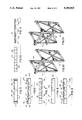
A collapsible bracing structure is shown generally at 10 as having a pair of spaced-apart side frames 12 and 14 connected by a number of elongated cross-braces 16 to define a rigid wood box 18 capable of unitizing and/or bracing a load in a manner as will be described.
Side frames 12 and 14 are identical structures and will be, therefore, described with reference to, arbitrarily, side frame 12. It should be understood that the herein described components of side frame 12 are similarly disposed on side frame 14. Referring to FIGS. 2-4, side frame 12 comprises a rectangular structure having a pair of spaced-apart, upright legs 20 and 22 connected by transverse elements 24, 26 and 28. All fixed connections herein described comprehend the use of threaded fasteners, such as screws, but are not to be understood as being so limited and envision the use of nails, glue, or any other effective securement means.
A pair of lower reinforcement blocks 30 and 32 are fixed to the lower portions of upright legs 20 and 22, respectively, and act to reinforce the junctions of the upright legs with respective end portions of transverse elements 28. A pair of upper reinforcement blocks 34 and 36 are attached to upper portions of upright legs 20 and 22, respectively, and reinforce the junctions of the upright members with respective opposite ends of transverse element 24.
In addition to lower reinforcement blocks 30, 32 and upper reinforcement blocks 34, 36, side frame 12 has additional stiffening means in the form of angled stiffeners. A pair of full length stiffeners 38 and 40 are mounted on opposing faces of side frame 12. Full length stiffener 38 is attached at one end to upper reinforcement block 34, is fastened at a central portion 42 to transverse element 26, and is attached at an opposite end to lower reinforcement block 32. Full length stiffener 40 is attached at one end to upper reinforcement block 36, attached at a central portion 44 to transverse element 26, and fixed at an opposite end to lower reinforcement block 30. A number of additional angled stiffeners are provided to enhance the rigidity of side frame 12. Angled stiffener 46 extends between transverse element 28 and lower reinforcement block 32. Angled stiffener 48 extends between transverse element 24 and upper reinforcement blocks 34. Angled stiffener 50 extends between upright leg 20 and transverse element 26. Angled stiffener 52 extends between upright leg 22 and transverse element 26. Together, the reinforcement blocks 30, 32, 34 and 36, together with stiffeners 38, 40 and 46, 48, 50 and 52 provide a rigid frame capable of withstanding excessive forces.
A pair of manually operable latches 53 and 54 are fixed to upper transverse element 24. Latch 53 comprises a spacer block 56 interconnecting a rotatable lock 58 to the side frame 12. Symmetrically spaced latch 54 includes a spacer block 60 and a rotatably mounted block 62. A pair of similar manually operable latches 64 and 66 are mounted on transverse element 26. Latch 64 has a spacer block 68 and a rotatable lock 70. Latch 66 has a spacer block 72 and a rotatable lock 74. Each of the rotatable locks 58, 62, 70 and 74 is pivotally fixed to the corresponding spacer block 56, 60, 68 and 72 by means of a threaded fastener interengaging each pair of corresponding elements. The fastener is advanced to a point at which the rotatable locks are frictionally engaged with the corresponding spacer blocks, but may be positioned easily by an individual.
As shown in FIG. 1, side frames 12 and 14 are spaced apart by elongated cross-braces 16. Upper cross-braces 76 and 78 engage the upper transverse element 24 of opposed side frames 12 and 14. Intermediate cross-braces 80 and 82 extend between the center transverse elements 26 of spaced-apart side frames 12 and 14. In manner described below, the cross-braces 76 and 78 engage manually operable latches 53 and 54, respectively, and intermediate cross- braces 80 and 82 engage manually operable latches 64 and 66, respectively.
Upper cross-braces 76 and 78 comprise similar structures and will herein be described with reference to, arbitrarily, upper cross-brace 76. Cross-brace 76 is an elongated L-shaped member having an top flange 84 and a perpendicular side flange 86 with a pair of spaced-apart notches 88. Each notch 88 is flanked by a pair of reinforcement blocks 90 on the underside of top flange 84 to reinforce the junction of the side flange 88 and top flange 84. A manually operable latch 92, comprising a spacer block 94 and rotatable lock 96, is mounted on an end 98 of the top flange 84, and a manually operable latch 100, comprising a spacer block 102 and rotatable lock 104, is mounted on an opposite end 106 of top flange 84.
Intermediate cross-braces 80 and 82 are similar structures and will be described herein with reference to, arbitrarily, cross-brace 80. Cross-brace 80 is an elongated L-shaped member having a top flange 108 and a perpendicular side flange 110 with a pair of oppositely spaced notches 112. Each of notches 112 is flanked by a pair of reinforcement blocks 114 for reinforcing the junction of top flange 108 and side flange 110.
The method of assembling the side frames 12 and 14 and cross-braces 76, 78 and 80, 82 will now be described. Referring to FIGS. 12-15, the side frames 12 and 14 are first arranged in a parallel spaced arrangement and extending longitudinally with respect to a trailer. Upper cross-brace 76 is first installed by placing the brace downward over the upper transverse elements 24 of the side frames in a direction shown by arrow 116. Notches 88 on side face 86 engage an upper end portion of upright leg 20 of side frames 12 and 14. A space 118 formed between reinforcement blocks 90 receives an end portion of upper transverse elements 24. Once the notches of cross-brace 76 are fully interlocked with each side frame, rotatable locks 58 are manually pivoted to engage a portion of top surface 84 and lock upper cross-brace 76 in place.
Intermediate cross-brace 80 is next locked into place. Cross-brace 80 is forced downwards in the direction of arrow 120 over end porticos of transverse elements 26. Notches 112 engage a portion of upright legs 20 of side frames 12 and 14, while spaces 122, formed between each pair of reinforcement blocks 114, are seated on end portions of transverse elements 26. Once the notches on intermediate cross-brace 80 are fully seated on side frames 12 and 14, rotatable locks 70 are pivoted to engage top surface 108 of cross-brace 80.
In a similar manner, upper cross-brace 78 is forced downwardly in the direction of arrow 124 to engage side frames 14 and 12. Rotatable locks 62 are then rotated to engage top surface 84. Intermediate cross-brace 82 is then forced downwardly in the direction of arrow 126 over end portions of transverse elements 26. Rotatable locks 104 are then pivoted to engage top surface 108 of the cross brace.
With this arrangement, an easily installed, rigid unitizer/brace structure may be installed within a truck trailer to separate a payload, as shown in FIGS. 18-20. In FIG. 18, the invention functions as a unitizing structure 128 positioned between end portions 130 and 132 of a truck payload. The structure 128 comprises a pair of opposed load-engaging faces 134 and 136 and a bottom surface 138 engaging the load-bearing surface 140 of a truck trailer. FIG. 19 illustrates a similar embodiment in which a second bracing structure 130 is provided at the rear of payload 132. With this arrangement, payload portions 130 and 132 are unitized, and payload 132 is prevented from shifting rearward and separating from load-bearing surface 140. A U-shaped bracket 142 is placed against the upright side frames 12 and 14 and is attached to the load-bearing surface 140 by means of nails or threaded fasteners to keep the side frames from separating from the load-bearing surface.
An alternative embodiment is shown in FIG. 20 wherein a number of structures 144 are laterally spaced in a longitudinally extending arrangement within a truck trailer to position a payload of flat materials 146, such as sheet steel.
In a preferred embodiment and as shown in FIG. 16, 17 and 22, the present invention is adapted to brace a plurality of discrete loads. A number of rigid blocks 148 are joined by means of elongated link members 150 each having a pair of oppositely spaced pairs of spacers 152 defining end notches 154 therebetween. Referring to FIG. 16, link members 150 engage adjacent upper cross-braces 156 and 158 to join rigid blocks 160 and 162 formed according to the present invention. The blocks 160 and 162 define interior cavities 164, 166 which are adapted to carry discrete loads, such as cylindrical rolls of paper. FIG. 17 shows the bracing strucure arranged seriatim for four rolls of paper each to be confined between linking members 150 so as to restrain the upper portion of the rolls against tipping and movement.
The above described invention provides a unitizing and bracing structure affording many advantages over existing devices. The apparatus is useful in equalizing the load between a pair of truck trailer axles as well as for avoiding the dangerous shifting of loads within a truck trailer. The device is versatile and can be used on each of the opposite ends of the load, intermediate the ends of the load and at the sides of the load. The device can be assembled and dismantled in a few minutes without any tools and is designed for reuse a multiplicity of times. The dismantled device can be stored in a very small space in the nose of the trailer to accommodate future loads. The device can be varied in height easily to accommodate loads of varying height. Except for the opposite side frame portions, the remaining components are interchangeable so that the cross-braces can be used with any number of side frames of varying heights. Because for a given customer the size of the trailer, the axle positions, and the type of loads to be carried are known quantities, the side frames can be appropriately sized to properly distribute the weight about the axles.

Claims (6)

I claim:
1. A collapsible bracing structure for bracing a load against shifting on a surface bearing the load, the collapsible bracing structure comprising:
a pair of laterally spaced frames extending in parallel on the load bearing surface, each frame having a pair of upright members connected by a plurality of vertically spaced transverse members;
an elongated cross brace extending between the frames and releasably connected therewith to define a rigid parallelepiped for bracing a load,
the cross brace being a generally L-shaped member having a substantially horizontal leg and a substantially vertical leg, said substantially horizontal leg contacting and resting on a transverse member on each frame when the bracing structure is assembled, said substantially vertical leg having a first notch engaged with one of the upright members of one side frame and a second notch engaged with one of the upright members of the other side frame whereby each upright member engaged with the substantially vertical leg fits within the corresponding notch to prevent lateral separation of the side frames; and
a latch on at least one of the side frames and movable into overlying engagement with the substantially horizontal leg for maintaining engagement of the cross brace with the upright members.
2. The collapsible bracing structure of claim 1 in which the latch is connected to a transverse member on one of the side frames.
3. The collapsible bracing structure of claim 2 in which the latch is pivotally connected to the transverse member.
4. The collapsible bracing structure of claim 3 in which a spacer block is interposed between the latch and the transverse member and abuts the one leg of the cross brace resting on the transverse member to maintain engagement of one of the notches on the other leg with a corresponding upright member.
5. In combination with a plurality of collapsible bracing structures according to claim 1, means for releasably connecting a pair of said structures when a pair of said structures are adjacently posed including, an elongated link extending between the structures and a manually operable latch on each structure for uniting the link therewith.
6. The combination of claim 5 in which the elongated link has a first notch engaged with the cross brace of one bracing structure and a second notch engaged with the cross brace of an adjacent bracing structure.
US07/607,819 1990-11-01 1990-11-01 Collapsible structure for unitizing and bracing a load in a trailer Expired - Fee Related US5181815A (en)

Priority Applications (1)

Application Number Priority Date Filing Date Title
US07/607,819 US5181815A (en) 1990-11-01 1990-11-01 Collapsible structure for unitizing and bracing a load in a trailer

Applications Claiming Priority (1)

Application Number Priority Date Filing Date Title
US07/607,819 US5181815A (en) 1990-11-01 1990-11-01 Collapsible structure for unitizing and bracing a load in a trailer

Publications (1)

Publication Number Publication Date
US5181815A true US5181815A (en) 1993-01-26

Family

ID=24433838

Family Applications (1)

Application Number Title Priority Date Filing Date
US07/607,819 Expired - Fee Related US5181815A (en) 1990-11-01 1990-11-01 Collapsible structure for unitizing and bracing a load in a trailer

Country Status (1)

Country Link
US (1) US5181815A (en)

Cited By (15)

* Cited by examiner, † Cited by third party
Publication number Priority date Publication date Assignee Title
US5660512A (en) * 1996-01-11 1997-08-26 Elze; Helmut Richard Apparatus to protect perishable products during transport
US6142550A (en) * 1998-04-27 2000-11-07 873968 Ontario Limited Van liner
US6260719B1 (en) * 1998-06-08 2001-07-17 Michael J. Azzopardi Method for converting pre-existing racking systems to dual pallet, vehicle loadable racking system
US6267253B1 (en) * 1999-08-19 2001-07-31 Spacehab, Inc. Logistics rack for space flight
US6360903B1 (en) * 1999-05-26 2002-03-26 Sagarte, S.A. Support for casks
US6405884B1 (en) * 1998-09-09 2002-06-18 Damotech Inc. Pallet rack reinforcement unit
US6497332B1 (en) * 2001-07-12 2002-12-24 Konstant Products, Inc. Pick deck
US20030010740A1 (en) * 2001-07-12 2003-01-16 Konstant Products, Inc. Pick deck
WO2004065169A1 (en) * 2003-01-23 2004-08-05 The Mattamy Corporation External support structure for securing a house during transport
US20080006593A1 (en) * 2006-07-05 2008-01-10 Northrop Grumman Corporation Modular rack design
US20100054906A1 (en) * 2006-07-11 2010-03-04 J&D Global, Ltd. Racking system and method of storing palletized items
US20110139733A1 (en) * 2009-06-15 2011-06-16 J&D Global., Ltd. Rack system
US20150068997A1 (en) * 2012-04-19 2015-03-12 Tokai Rubber Industries, Ltd. Automated Warehouse Rack
US20150359329A1 (en) * 2014-06-13 2015-12-17 Environmental Compliance Solutions, Llc Adjustable rack and method of making and using the same
US10752441B1 (en) * 2019-03-04 2020-08-25 Frazier Industrial Company Storage system having dual-row pallet bays

Citations (47)

* Cited by examiner, † Cited by third party
Publication number Priority date Publication date Assignee Title
US1499229A (en) * 1922-09-08 1924-06-24 William J Laffey Bulkhead for freight cars
US1969656A (en) * 1931-11-03 1934-08-07 Marlowe Devices Inc Knockdown scaffolding
US2166918A (en) * 1938-05-03 1939-07-18 Mcmullen John Portable bulkhead
US2204075A (en) * 1939-07-21 1940-06-11 William F Eisensmith Load bracing device
US2226570A (en) * 1938-04-05 1940-12-31 William W Mccaw Collapsible support for fluoroscopic units
US2279325A (en) * 1941-04-29 1942-04-14 Kaldizar Lewis Gun rack
US2514466A (en) * 1947-04-25 1950-07-11 Robert J Bildhauer Freight load brace
US2522096A (en) * 1948-11-23 1950-09-12 Ted E Cooke Supporting stand for tables, basins, and the like
US2812728A (en) * 1953-06-29 1957-11-12 Car Blocking Inc Lading blocking device
US2819688A (en) * 1954-08-24 1958-01-14 James L Hall Attachment for railroad flat cars
US2895431A (en) * 1957-04-22 1959-07-21 Ford Grain Door Company Freight car bulkhead
US2895619A (en) * 1958-06-27 1959-07-21 Midland Machine Corp Storage rack
CA580720A (en) * 1959-08-04 Evans Products Company Freight loading apparatus
GB818459A (en) * 1954-05-03 1959-08-19 Frank Richard Noakes Improvements in or relating to metal rack constructions
US2901987A (en) * 1954-04-12 1959-09-01 Chrysler Corp Car loading apparatus
US2937767A (en) * 1958-12-15 1960-05-24 Unistrut Products Company Shelving structure
US2944676A (en) * 1958-04-14 1960-07-12 Allen Iron & Steel Company Storage rack
US2978993A (en) * 1957-04-02 1961-04-11 James L Hall Attachment for railroad flat car
AT224853B (en) * 1960-03-03 1962-12-10 Fausto Nember frame
US3183855A (en) * 1962-02-26 1965-05-18 Pullman Inc Load retainer
US3235038A (en) * 1963-04-10 1966-02-15 Harsco Corp Folding scaffold
US3337061A (en) * 1965-09-27 1967-08-22 Storage Systems Inc Drive-in storage rack
US3365073A (en) * 1965-10-07 1968-01-23 Storage Systems Inc Adjustable clamp for storage racks
US3463325A (en) * 1967-06-22 1969-08-26 Interlake Steel Corp Pallet rack beam retainer
US3606842A (en) * 1969-05-05 1971-09-21 Basil George Verbick Adjustable retainer
US3625372A (en) * 1970-07-06 1971-12-07 James A Mackenzie Pallet rack
US3637094A (en) * 1970-05-19 1972-01-25 Sperry Rand Corp Bulkhead
US3647080A (en) * 1970-06-12 1972-03-07 Inca Metal Products Corp Structural element and structure
US3651950A (en) * 1970-08-11 1972-03-28 Sheller Globe Corp Support for suspended files
US3685665A (en) * 1970-10-23 1972-08-22 Triax Co Knockdown storage frame and components
NL7311859A (en) * 1973-08-29 1975-03-04 Parco Tech Handelsonderneming Collapsible transport rack has two side members - connected by hinged crosswise rods and removable ties
US3964608A (en) * 1974-07-15 1976-06-22 Ppg Industries, Inc. Adjustable back support for shipping bins
US4030612A (en) * 1976-06-03 1977-06-21 Robert Gray Pallet racks
US4074812A (en) * 1975-12-11 1978-02-21 The Paltier Corporation Pallet rack
US4079678A (en) * 1975-12-05 1978-03-21 Cogan Wire & Metal Products Limited Shelving system
US4127071A (en) * 1975-11-24 1978-11-28 Ppg Industries, Inc. Railway car shipping support structure
US4189250A (en) * 1978-12-28 1980-02-19 Jervis B. Webb Company Self-locking connector for storage racks
US4261470A (en) * 1979-05-01 1981-04-14 Dolan Donald L Collapsible rack
US4285436A (en) * 1978-12-26 1981-08-25 Speedshelf International, Inc. Integral locking tab for storage racks
US4360298A (en) * 1978-08-07 1982-11-23 Ppg Industries, Inc. Trailer transverse rack assembly for shipping sheets
GB2142701A (en) * 1983-01-29 1985-01-23 Ponable Ltd Dismountable framework
US4498824A (en) * 1981-08-13 1985-02-12 The Budd Company Extendible and contractible vehicle bulkhead
US4545710A (en) * 1982-07-29 1985-10-08 Sun Carriers, Inc. Apparatus for automated less-than-truck load shipments
US4708252A (en) * 1983-12-16 1987-11-24 The Kingston-Warren Corporation Storage rack system
US4743151A (en) * 1984-10-12 1988-05-10 Haberkorn Robert W Structure and method for unitizing and bracing a load in a trailer
US5012938A (en) * 1990-02-16 1991-05-07 S&K Enterprises, Inc. Storage rack corner post
US5037256A (en) * 1989-12-04 1991-08-06 Schroeder Robert C Dunnage bar lock

Patent Citations (47)

* Cited by examiner, † Cited by third party
Publication number Priority date Publication date Assignee Title
CA580720A (en) * 1959-08-04 Evans Products Company Freight loading apparatus
US1499229A (en) * 1922-09-08 1924-06-24 William J Laffey Bulkhead for freight cars
US1969656A (en) * 1931-11-03 1934-08-07 Marlowe Devices Inc Knockdown scaffolding
US2226570A (en) * 1938-04-05 1940-12-31 William W Mccaw Collapsible support for fluoroscopic units
US2166918A (en) * 1938-05-03 1939-07-18 Mcmullen John Portable bulkhead
US2204075A (en) * 1939-07-21 1940-06-11 William F Eisensmith Load bracing device
US2279325A (en) * 1941-04-29 1942-04-14 Kaldizar Lewis Gun rack
US2514466A (en) * 1947-04-25 1950-07-11 Robert J Bildhauer Freight load brace
US2522096A (en) * 1948-11-23 1950-09-12 Ted E Cooke Supporting stand for tables, basins, and the like
US2812728A (en) * 1953-06-29 1957-11-12 Car Blocking Inc Lading blocking device
US2901987A (en) * 1954-04-12 1959-09-01 Chrysler Corp Car loading apparatus
GB818459A (en) * 1954-05-03 1959-08-19 Frank Richard Noakes Improvements in or relating to metal rack constructions
US2819688A (en) * 1954-08-24 1958-01-14 James L Hall Attachment for railroad flat cars
US2978993A (en) * 1957-04-02 1961-04-11 James L Hall Attachment for railroad flat car
US2895431A (en) * 1957-04-22 1959-07-21 Ford Grain Door Company Freight car bulkhead
US2944676A (en) * 1958-04-14 1960-07-12 Allen Iron & Steel Company Storage rack
US2895619A (en) * 1958-06-27 1959-07-21 Midland Machine Corp Storage rack
US2937767A (en) * 1958-12-15 1960-05-24 Unistrut Products Company Shelving structure
AT224853B (en) * 1960-03-03 1962-12-10 Fausto Nember frame
US3183855A (en) * 1962-02-26 1965-05-18 Pullman Inc Load retainer
US3235038A (en) * 1963-04-10 1966-02-15 Harsco Corp Folding scaffold
US3337061A (en) * 1965-09-27 1967-08-22 Storage Systems Inc Drive-in storage rack
US3365073A (en) * 1965-10-07 1968-01-23 Storage Systems Inc Adjustable clamp for storage racks
US3463325A (en) * 1967-06-22 1969-08-26 Interlake Steel Corp Pallet rack beam retainer
US3606842A (en) * 1969-05-05 1971-09-21 Basil George Verbick Adjustable retainer
US3637094A (en) * 1970-05-19 1972-01-25 Sperry Rand Corp Bulkhead
US3647080A (en) * 1970-06-12 1972-03-07 Inca Metal Products Corp Structural element and structure
US3625372A (en) * 1970-07-06 1971-12-07 James A Mackenzie Pallet rack
US3651950A (en) * 1970-08-11 1972-03-28 Sheller Globe Corp Support for suspended files
US3685665A (en) * 1970-10-23 1972-08-22 Triax Co Knockdown storage frame and components
NL7311859A (en) * 1973-08-29 1975-03-04 Parco Tech Handelsonderneming Collapsible transport rack has two side members - connected by hinged crosswise rods and removable ties
US3964608A (en) * 1974-07-15 1976-06-22 Ppg Industries, Inc. Adjustable back support for shipping bins
US4127071A (en) * 1975-11-24 1978-11-28 Ppg Industries, Inc. Railway car shipping support structure
US4079678A (en) * 1975-12-05 1978-03-21 Cogan Wire & Metal Products Limited Shelving system
US4074812A (en) * 1975-12-11 1978-02-21 The Paltier Corporation Pallet rack
US4030612A (en) * 1976-06-03 1977-06-21 Robert Gray Pallet racks
US4360298A (en) * 1978-08-07 1982-11-23 Ppg Industries, Inc. Trailer transverse rack assembly for shipping sheets
US4285436A (en) * 1978-12-26 1981-08-25 Speedshelf International, Inc. Integral locking tab for storage racks
US4189250A (en) * 1978-12-28 1980-02-19 Jervis B. Webb Company Self-locking connector for storage racks
US4261470A (en) * 1979-05-01 1981-04-14 Dolan Donald L Collapsible rack
US4498824A (en) * 1981-08-13 1985-02-12 The Budd Company Extendible and contractible vehicle bulkhead
US4545710A (en) * 1982-07-29 1985-10-08 Sun Carriers, Inc. Apparatus for automated less-than-truck load shipments
GB2142701A (en) * 1983-01-29 1985-01-23 Ponable Ltd Dismountable framework
US4708252A (en) * 1983-12-16 1987-11-24 The Kingston-Warren Corporation Storage rack system
US4743151A (en) * 1984-10-12 1988-05-10 Haberkorn Robert W Structure and method for unitizing and bracing a load in a trailer
US5037256A (en) * 1989-12-04 1991-08-06 Schroeder Robert C Dunnage bar lock
US5012938A (en) * 1990-02-16 1991-05-07 S&K Enterprises, Inc. Storage rack corner post

Cited By (22)

* Cited by examiner, † Cited by third party
Publication number Priority date Publication date Assignee Title
US5660512A (en) * 1996-01-11 1997-08-26 Elze; Helmut Richard Apparatus to protect perishable products during transport
US6142550A (en) * 1998-04-27 2000-11-07 873968 Ontario Limited Van liner
US6260719B1 (en) * 1998-06-08 2001-07-17 Michael J. Azzopardi Method for converting pre-existing racking systems to dual pallet, vehicle loadable racking system
US6405884B1 (en) * 1998-09-09 2002-06-18 Damotech Inc. Pallet rack reinforcement unit
US6523706B2 (en) * 1999-05-26 2003-02-25 Sagarte, S.A. Support for casks
US6360903B1 (en) * 1999-05-26 2002-03-26 Sagarte, S.A. Support for casks
US6536612B2 (en) * 1999-05-26 2003-03-25 Sagarte, S.A. Support for casks
US6267253B1 (en) * 1999-08-19 2001-07-31 Spacehab, Inc. Logistics rack for space flight
US6691880B2 (en) * 2001-07-12 2004-02-17 Konstant Products, Inc. Pick deck
US20030010740A1 (en) * 2001-07-12 2003-01-16 Konstant Products, Inc. Pick deck
US6497332B1 (en) * 2001-07-12 2002-12-24 Konstant Products, Inc. Pick deck
WO2004065169A1 (en) * 2003-01-23 2004-08-05 The Mattamy Corporation External support structure for securing a house during transport
US20080006593A1 (en) * 2006-07-05 2008-01-10 Northrop Grumman Corporation Modular rack design
US20100054906A1 (en) * 2006-07-11 2010-03-04 J&D Global, Ltd. Racking system and method of storing palletized items
US20110139733A1 (en) * 2009-06-15 2011-06-16 J&D Global., Ltd. Rack system
US20150068997A1 (en) * 2012-04-19 2015-03-12 Tokai Rubber Industries, Ltd. Automated Warehouse Rack
US9296559B2 (en) * 2012-04-19 2016-03-29 Sumitomo Riko Company Limited Automated warehouse rack
US20150359329A1 (en) * 2014-06-13 2015-12-17 Environmental Compliance Solutions, Llc Adjustable rack and method of making and using the same
US9504319B2 (en) * 2014-06-13 2016-11-29 Environmental Compliance Solutions, Llc Adjustable rack and method of making and using the same
US9755201B2 (en) * 2014-06-13 2017-09-05 Environmental Compliance Solutions, Llc Adjustable rack and method of making and using the same
US10752441B1 (en) * 2019-03-04 2020-08-25 Frazier Industrial Company Storage system having dual-row pallet bays
US11370613B2 (en) 2019-03-04 2022-06-28 Frazier Industrial Company Pallet bay guide system

Similar Documents

Publication Publication Date Title
US5181815A (en) Collapsible structure for unitizing and bracing a load in a trailer
US4226465A (en) Load supporting frame assembly
AU2014203159B2 (en) Container roll out warehousing system
US5513941A (en) Rolling cargo apparatus
US3217449A (en) Scaffold rack
DE2933427C2 (en) Container for holding the modular components of a railroad car
US5494167A (en) Returnable case
GB2036659A (en) Load supporting frame
US4465413A (en) Cargo retainer
US20020139798A1 (en) Shipping pallet
US6572322B2 (en) Mounting system for truck mounted beverage handler
US4743151A (en) Structure and method for unitizing and bracing a load in a trailer
GB1602738A (en) Load-carrying vehicles
RU170394U1 (en) Frame
DE69209509T2 (en) Transportation of goods
US5269639A (en) System for shipping products and stabilizing them from shifting sidewise on vehicle
US5418038A (en) Space filling device
US3734315A (en) Means for transporting palletized loads
US5259647A (en) Low bed oversized trailer
EP0641685A1 (en) Device for securing the transport of containers
DE19815236A1 (en) Lean-to ladder with lockable links for transporting objects e.g. used in filming and photographing
DE19706493A1 (en) Goods vehicle with additional upper load platforms
US3195944A (en) Vehicle wall bracing means
US5662343A (en) Container base with three perpendicular fixing elements in the corners
JP3251779U (en) Ladder for climbing up and down the loading platform

Legal Events

Date Code Title Description
FEPP Fee payment procedure

Free format text: PAYOR NUMBER ASSIGNED (ORIGINAL EVENT CODE: ASPN); ENTITY STATUS OF PATENT OWNER: SMALL ENTITY

FEPP Fee payment procedure

Free format text: PAYER NUMBER DE-ASSIGNED (ORIGINAL EVENT CODE: RMPN); ENTITY STATUS OF PATENT OWNER: SMALL ENTITY

FPAY Fee payment

Year of fee payment: 4

FEPP Fee payment procedure

Free format text: PAYOR NUMBER ASSIGNED (ORIGINAL EVENT CODE: ASPN); ENTITY STATUS OF PATENT OWNER: SMALL ENTITY

FPAY Fee payment

Year of fee payment: 8

REMI Maintenance fee reminder mailed
LAPS Lapse for failure to pay maintenance fees
STCH Information on status: patent discontinuation

Free format text: PATENT EXPIRED DUE TO NONPAYMENT OF MAINTENANCE FEES UNDER 37 CFR 1.362

FP Lapsed due to failure to pay maintenance fee

Effective date: 20050126