US5170102A - Picture display device - Google Patents

Picture display device Download PDF

Info

Publication number
US5170102A
US5170102A US07/505,088 US50508890A US5170102A US 5170102 A US5170102 A US 5170102A US 50508890 A US50508890 A US 50508890A US 5170102 A US5170102 A US 5170102A
Authority
US
United States
Prior art keywords
display screen
deflection
display
display device
short axis
Prior art date
Legal status (The legal status is an assumption and is not a legal conclusion. Google has not performed a legal analysis and makes no representation as to the accuracy of the status listed.)
Expired - Fee Related
Application number
US07/505,088
Inventor
Albertus A. S. Sluyterman
Marinus L. A. Vrinten
Fransiscus M. P. P. Doomernik
Current Assignee (The listed assignees may be inaccurate. Google has not performed a legal analysis and makes no representation or warranty as to the accuracy of the list.)
US Philips Corp
Original Assignee
US Philips Corp
Priority date (The priority date is an assumption and is not a legal conclusion. Google has not performed a legal analysis and makes no representation as to the accuracy of the date listed.)
Filing date
Publication date
Application filed by US Philips Corp filed Critical US Philips Corp
Assigned to U.S. PHILIPS CORPORATION, A CORP. OF DE reassignment U.S. PHILIPS CORPORATION, A CORP. OF DE ASSIGNMENT OF ASSIGNORS INTEREST. Assignors: DOOMERNIK, FRANSISCUS M.P.P, SLUYTERMAN, ALBERTUS A.S., VRINTEN, MARINUS L.A.
Application granted granted Critical
Publication of US5170102A publication Critical patent/US5170102A/en
Anticipated expiration legal-status Critical
Expired - Fee Related legal-status Critical Current

Links

Images

Classifications

    • HELECTRICITY
    • H01ELECTRIC ELEMENTS
    • H01JELECTRIC DISCHARGE TUBES OR DISCHARGE LAMPS
    • H01J31/00Cathode ray tubes; Electron beam tubes
    • H01J31/08Cathode ray tubes; Electron beam tubes having a screen on or from which an image or pattern is formed, picked up, converted, or stored
    • H01J31/10Image or pattern display tubes, i.e. having electrical input and optical output; Flying-spot tubes for scanning purposes
    • H01J31/20Image or pattern display tubes, i.e. having electrical input and optical output; Flying-spot tubes for scanning purposes for displaying images or patterns in two or more colours
    • H01J31/201Image or pattern display tubes, i.e. having electrical input and optical output; Flying-spot tubes for scanning purposes for displaying images or patterns in two or more colours using a colour-selection electrode
    • H01J31/203Image or pattern display tubes, i.e. having electrical input and optical output; Flying-spot tubes for scanning purposes for displaying images or patterns in two or more colours using a colour-selection electrode with more than one electron beam
    • H01J31/206Image or pattern display tubes, i.e. having electrical input and optical output; Flying-spot tubes for scanning purposes for displaying images or patterns in two or more colours using a colour-selection electrode with more than one electron beam with three coplanar electron beams
    • HELECTRICITY
    • H01ELECTRIC ELEMENTS
    • H01JELECTRIC DISCHARGE TUBES OR DISCHARGE LAMPS
    • H01J29/00Details of cathode-ray tubes or of electron-beam tubes of the types covered by group H01J31/00
    • H01J29/46Arrangements of electrodes and associated parts for generating or controlling the ray or beam, e.g. electron-optical arrangement
    • H01J29/70Arrangements for deflecting ray or beam
    • H01J29/72Arrangements for deflecting ray or beam along one straight line or along two perpendicular straight lines
    • H01J29/76Deflecting by magnetic fields only

Definitions

  • the invention relates to a picture display device comprising a colour display tube having an elongate display screen with a short axis and a long axis, which screen is provided on an inner surface, a colour selection system arranged in front of the display screen, an electron gun system arranged opposite the display screen for producing co-planar beams, and a deflection system arranged between the electron gun system and the display screen.
  • Conventional picture display devices of the type described above often have an electron gun system with three guns which are located in one plane.
  • the plane in which the undeflected beams are located is parallel to the long axis of the display screen.
  • the orthogonal deflection fields generated by the deflection system upon energization generally have such a (pincushion and barrel) configuration, viewed in planes transverse to the axis of the display tube, that the display device is self-convergent.
  • a problem in this type of display device in its current form is the increase in the dimension of the spot in the direction of the long axis of the display screen as the deflection in that direction increases. This problem is not new, but it will become even more manifest in future HDTV systems.
  • a picture display device is characterized in that the plane in which the undeflected beams are located is parallel to the short axis of the display screen, in that the deflection system has terminals to be connected to a signal generator for scanning the display screen in a raster having a plurality of lines oriented along the short axis of the display screen and in that the deflection system comprises a first system of deflection coils for generating, upon energization, a substantially pincushion-shaped deflection field for deflecting the beams in the direction of the short axis of the display screen and a second system of deflection coils for generating, upon energization, a substantially barrel-shaped deflection field for deflecting the beams in the direction of the long axis of the display screen.
  • the above-mentioned solution involves a rotation of the plane of the gun, the deflection system as well as the scanning direction associated with the higher of the two beam deflection frequencies through an angle of 90° relative to their conventional orientation.
  • the properties of self-convergence, if any, are not changed.
  • Rotation of the gun plane and deflection system has the advantage that the unfavourable spot growth per cm is directed along the short axis of the display tube.
  • the horizontal spot growth per cm along the horizontal axis is larger than the vertical spot growth along the vertical axis. This is acceptable in conventional systems, but it is unacceptable in (future) HDTV systems.
  • This means that the use of a rotated gun plane and deflection system with respect to the spot growth will be more and more advantageous as the ratio between the short axis of the display screen and the long axis of the display screen (the "aspect ratio") is smaller and is particularly smaller than 3:4 (certain HDTV systems use, for example a 9:16 tube).
  • a colour selection system with taut wires as well as a system comprising a mask sheet having an arrangement of apertures and a display screen compatible therewith can be used.
  • High-resolution monitor tubes often have mask sheets with an arrangement of circular apertures and a corresponding arrangement of phosphor dots.
  • a preferred embodiment of the device according to the invention is characterized in that the display screen comprises elongate phosphor areas whose longitudinal axes extend transversely to the short sides of the display screen and in that the colour selection system comprises a mask sheet having an arrangement of elongate apertures whose longitudinal axes extend transversely to the short sides of the display screen.
  • FIG. 1 is a longitudinal section through a colour display tube
  • FIG. 2 is a diagrammatic front elevation of an arrangement of a conventional gun system and a deflection coil system
  • FIG. 3 shows the shape of a raster scanned by the gun-coil arrangement of FIG. 2;
  • FIG. 4 is a diagrammatic front elevation of an arrangement of a gun system and a deflection coil system according to the invention
  • FIG. 5 shows the shape of a raster scanned by the gun-coil arrangement of FIG. 4 in accordance with horizontal lines;
  • FIG. 6 is a diagrammatic front elevation of an arrangement of a gun system and a deflection coil system according to the invention.
  • FIG. 7 shows the shape of a raster scanned by the gun-coil arrangement of FIG. 6 in accordance with vertical lines;
  • FIG. 8 shows relative spot dimensions in the top right quadrant of the display screen of a conventional display tube having a 3:4 aspect ratio
  • FIG. 9 shows relative spot dimensions in the top right quadrant of the display screen of a convention display tube having a 9:16 aspect ratio
  • FIG. 10 shows relative spot dimensions in the top right quadrant of the display screen of a display tube of a display system according to the invention
  • FIG. 11 is a plan view of a shadow mask to be used in a display tube for a display device according to the invention.
  • FIG. 12 is a plan view of a display screen to be used in combination with the shadow mask of FIG. 11.
  • a colour electron beam tube 1 generally has a front portion 2, a funnel portion 3 and a neck portion 4.
  • the front portion 2 is provided with a fluorescent display screen 2a constituted by luminescent materials for the three primary colours red, green and blue, and a shadow mask 5 serving as a colour selection means.
  • the neck portion 4 comprises an electron gun 6 for emitting electron beams 7.
  • the funnel portion 3 connects the front portion 2 and the neck portion 4 in order to define a vacuum space and a deflection system 18 comprising two sets of deflection coils 19a, 19b and 20a, 20b (see FIG. 6) is externally mounted in the area of transition between the funnel and neck portions.
  • the deflection system 18 is connected to a signal generator 15 for scanning the display screen 2a in accordance with rasters having lines parallel to a display screen axis.
  • a frame comprises two or more fields, or, alternatively, a picture is formed by one field.
  • a frame is composed of 2 interlaced fields of 3121/2 lines each, the field frequency being 50 Hz and the line frequency being 15,625 Hz. Scanning at the signal source in the studio is identical to scanning upon display. This is ensured by synchronizing signals which are transmitted together with the picture information.
  • the line frequency may be higher than the frequency prescribed by a television standard.
  • So-called high-definition television (HDTV) systems are also proposed in which the line frequency in the display device is very high, for example 62.5 kHz, which is 4 times as high as the line frequency in the current television standard.
  • the electron gun 6 arranged in the neck portion 4 is of the in-line type.
  • FIG. 2 shows three co-planar electron beams R, G, B which can be generated by an electron gun system 6.
  • a pair 9a, 9b of deflection coils is used for deflecting the electron beams across a display screen in a direction parallel to the plane of the non-deflected beams, and a pair 10a, 10b of deflection coils is used for deflection in a direction transverse to said plane.
  • both coil pairs are formed as saddle coils. However, they may also be in the form of toroidal coils, particularly the coil pair 10a, 10b.
  • the electron gun system 6 and the deflection coil system in FIG. 2 are arranged in a conventional manner. In conventional display systems such an arrangement is used to scan a display screen in a raster having a plurality of lines parallel to the long axis of the display screen (FIG. 3).
  • FIG. 8 is representative of the spot growth in a conventional self-convergent tube-coil combination with a 3:4 aspect ratio at which the deflection angle is maintained constant across the direction of the diagonal. For smaller aspect ratios the detrimental effect of spot growth in the x direction will even be stronger.
  • FIG. 9 which is representative of the spot growth in a display tube having a 9:16 aspect ratio.
  • FIG. 10 is representative of the spot growth in such a display tube having a 9:16 aspect ratio.
  • the scanning section is adapted to scan the lines in the vertical direction, a plurality of vertical lines constituting a field, the vertical line frequency being many times higher than the horizontal field frequency
  • the video signal processing section comprising a scan direction transposition circuit for receiving the picture information and for sequentially assigning picture information to elements of the vertically scanned lines.
  • the scan directions are transposed, the lines being scanned vertically, preferably from top to bottom at the highest scanning frequency, namely the line frequency, and the horizontal scanning, preferably from left to right, at the lowest scanning frequency, namely the field frequency.
  • the raster distortion at the long sides of the raster can be easily corrected by means of an electronic correction circuit (which modulates the amplitude of the deflection voltages which are applied to the coil system 20a, 20b (FIG. 6) deflecting in the y direction).
  • an electronic correction circuit which modulates the amplitude of the deflection voltages which are applied to the coil system 20a, 20b (FIG. 6) deflecting in the y direction.
  • the scan at the high frequency thus takes place in the direction of the short axis of the display screen and the scan at the low frequency takes place in the direction of the long axis of the display screen.
  • the field configuration of the deflection field generated by coil system 19a, 19b for deflection in the x direction is barrel-shaped and the field configuration of the deflection field generated by coil system 20a, 20b (which has the lowest impedance and is preferably arranged closest to the electron beams) for deflection in the y direction is pincushion-shaped.
  • the shadow mask which is used may be, for example a (hexagonal) apertured mask, but as already noted hereinbefore it is advantageous from a manufacturing-technical (inter alia etching-technical) point of view to use a "slit" mask having slits extending parallel to the long axis of the shadow mask, particularly in display tubes having an aspect ratio of less than 3:4.
  • This shadow mask then co-operates in the display tube with a display screen having elongate phosphor areas which extend parallel to the longitudinal axis of the display screen.

Abstract

Picture display device comprising an in-line color display tube having an elongate display screen with a short axis and a long axis, which screen is provided on an inner surface, and a deflection system. The plane in which the undeflected electron beams are located is parallel to the short axis of the display screen. The deflection system comprises a first system of deflection coils for generating a substantially pincushion-shaped deflection field in the direction of the short axis of the display screen and a second system of deflection coils for generating a substantially barrel-shaped deflection field in the direction of the long axis of the display screen. The deflection system has terminals to be connected to a signal generator for scanning the display screen in a raster having a plurality of lines oriented along the short axis of the display screen.

Description

BACKGROUND OF THE INVENTION
The invention relates to a picture display device comprising a colour display tube having an elongate display screen with a short axis and a long axis, which screen is provided on an inner surface, a colour selection system arranged in front of the display screen, an electron gun system arranged opposite the display screen for producing co-planar beams, and a deflection system arranged between the electron gun system and the display screen.
Conventional picture display devices of the type described above often have an electron gun system with three guns which are located in one plane. The plane in which the undeflected beams are located is parallel to the long axis of the display screen. The orthogonal deflection fields generated by the deflection system upon energization generally have such a (pincushion and barrel) configuration, viewed in planes transverse to the axis of the display tube, that the display device is self-convergent.
A problem in this type of display device in its current form is the increase in the dimension of the spot in the direction of the long axis of the display screen as the deflection in that direction increases. This problem is not new, but it will become even more manifest in future HDTV systems.
SUMMARY OF THE INVENTION
It is an object of the invention to provide a solution to the problem described above (and where applicable, while maintaining properties of self-convergence).
To this end a picture display device according to the invention is characterized in that the plane in which the undeflected beams are located is parallel to the short axis of the display screen, in that the deflection system has terminals to be connected to a signal generator for scanning the display screen in a raster having a plurality of lines oriented along the short axis of the display screen and in that the deflection system comprises a first system of deflection coils for generating, upon energization, a substantially pincushion-shaped deflection field for deflecting the beams in the direction of the short axis of the display screen and a second system of deflection coils for generating, upon energization, a substantially barrel-shaped deflection field for deflecting the beams in the direction of the long axis of the display screen.
The above-mentioned solution involves a rotation of the plane of the gun, the deflection system as well as the scanning direction associated with the higher of the two beam deflection frequencies through an angle of 90° relative to their conventional orientation. The properties of self-convergence, if any, are not changed.
Rotation of the gun plane and deflection system has the advantage that the unfavourable spot growth per cm is directed along the short axis of the display tube.
In current self-convergent tube-coil systems the horizontal spot growth per cm along the horizontal axis is larger than the vertical spot growth along the vertical axis. This is acceptable in conventional systems, but it is unacceptable in (future) HDTV systems. This means that the use of a rotated gun plane and deflection system with respect to the spot growth will be more and more advantageous as the ratio between the short axis of the display screen and the long axis of the display screen (the "aspect ratio") is smaller and is particularly smaller than 3:4 (certain HDTV systems use, for example a 9:16 tube). However, such a configuration has a north-south raster distortion (the raster distortion at the long sides) which is hard to correct, both electronically and by changing the coil design, as contrasted to the east-west raster distortion (the raster distortion at the short sides) which can easily be corrected both electronically and by changing the coil design. Rotation of the scanning direction associated with the higher beam deflection frequency in the direction of the short axis of the display screen has the advantage that the east-west raster distortion correction can be easily realised from a coil-design point of view and the north-south raster distortion correction can be easily realised by means of an electronic correction circuit. This is utilized in an embodiment of the device according to the invention.
In a device according to the invention a colour selection system with taut wires as well as a system comprising a mask sheet having an arrangement of apertures and a display screen compatible therewith can be used. High-resolution monitor tubes often have mask sheets with an arrangement of circular apertures and a corresponding arrangement of phosphor dots.
A preferred embodiment of the device according to the invention is characterized in that the display screen comprises elongate phosphor areas whose longitudinal axes extend transversely to the short sides of the display screen and in that the colour selection system comprises a mask sheet having an arrangement of elongate apertures whose longitudinal axes extend transversely to the short sides of the display screen.
From a manufacturing-technical point of view it is an advantage, which is all the more important as the display screen and hence the mask is more elongate, that in the above-described preferred embodiment of the device according to the invention the elongate apertures extend in the longitudinal direction of the mask instead of transversely to the longitudinal direction as in conventional shadow mask display tubes.
BRIEF DESCRIPTION OF THE DRAWING
An embodiment of the invention will now be described in greater detail by way of example with reference to the accompanying drawing figures in which:
FIG. 1 is a longitudinal section through a colour display tube;
FIG. 2 is a diagrammatic front elevation of an arrangement of a conventional gun system and a deflection coil system;
FIG. 3 shows the shape of a raster scanned by the gun-coil arrangement of FIG. 2;
FIG. 4 is a diagrammatic front elevation of an arrangement of a gun system and a deflection coil system according to the invention;
FIG. 5 shows the shape of a raster scanned by the gun-coil arrangement of FIG. 4 in accordance with horizontal lines;
FIG. 6 is a diagrammatic front elevation of an arrangement of a gun system and a deflection coil system according to the invention;
FIG. 7 shows the shape of a raster scanned by the gun-coil arrangement of FIG. 6 in accordance with vertical lines;
FIG. 8 shows relative spot dimensions in the top right quadrant of the display screen of a conventional display tube having a 3:4 aspect ratio;
FIG. 9 shows relative spot dimensions in the top right quadrant of the display screen of a convention display tube having a 9:16 aspect ratio;
FIG. 10 shows relative spot dimensions in the top right quadrant of the display screen of a display tube of a display system according to the invention;
FIG. 11 is a plan view of a shadow mask to be used in a display tube for a display device according to the invention; and
FIG. 12 is a plan view of a display screen to be used in combination with the shadow mask of FIG. 11.
DESCRIPTION OF THE PREFERRED EMBODIMENT
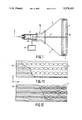
As is shown in FIG. 1, a colour electron beam tube 1 generally has a front portion 2, a funnel portion 3 and a neck portion 4.
The front portion 2 is provided with a fluorescent display screen 2a constituted by luminescent materials for the three primary colours red, green and blue, and a shadow mask 5 serving as a colour selection means.
The neck portion 4 comprises an electron gun 6 for emitting electron beams 7. The funnel portion 3 connects the front portion 2 and the neck portion 4 in order to define a vacuum space and a deflection system 18 comprising two sets of deflection coils 19a, 19b and 20a, 20b (see FIG. 6) is externally mounted in the area of transition between the funnel and neck portions. The deflection system 18 is connected to a signal generator 15 for scanning the display screen 2a in accordance with rasters having lines parallel to a display screen axis.
In conventional picture display devices the picture is formed in that lines are substantially horizontally scanned from left to right, for example on the display screen of a picture display tube, while picture information is applied to electrodes of the tube. Thus, picture information is assigned to the elements of the horizontally scanned lines. The successive lines are scanned from top to bottom so that a given number of lines forms a field. A frame comprises two or more fields, or, alternatively, a picture is formed by one field. For example, according to the European television broadcasting standard a frame is composed of 2 interlaced fields of 3121/2 lines each, the field frequency being 50 Hz and the line frequency being 15,625 Hz. Scanning at the signal source in the studio is identical to scanning upon display. This is ensured by synchronizing signals which are transmitted together with the picture information.
In picture display devices for displaying digitally generated text, so-called monitors, the line frequency may be higher than the frequency prescribed by a television standard. So-called high-definition television (HDTV) systems are also proposed in which the line frequency in the display device is very high, for example 62.5 kHz, which is 4 times as high as the line frequency in the current television standard.
The electron gun 6 arranged in the neck portion 4 is of the in-line type.
FIG. 2 shows three co-planar electron beams R, G, B which can be generated by an electron gun system 6. A pair 9a, 9b of deflection coils is used for deflecting the electron beams across a display screen in a direction parallel to the plane of the non-deflected beams, and a pair 10a, 10b of deflection coils is used for deflection in a direction transverse to said plane. In the case shown both coil pairs are formed as saddle coils. However, they may also be in the form of toroidal coils, particularly the coil pair 10a, 10b. The electron gun system 6 and the deflection coil system in FIG. 2 are arranged in a conventional manner. In conventional display systems such an arrangement is used to scan a display screen in a raster having a plurality of lines parallel to the long axis of the display screen (FIG. 3).
When using a self-convergent tube-coil combination a typical (pincushion) raster distortion is produced at the short sides of the raster. This distortion can be easily corrected (by means of an electronic correction circuit). The raster distortion occurring at the long sides of the raster can not easily be corrected by electronic means and is generally corrected by taking measures in the deflection coil system itself, said measures changing the deflection field distribution near the screen-sided end of the deflection unit. As will be explained with reference to FIG. 8, the spot growth is small in the y direction, but considerable in the x direction. FIG. 8 is representative of the spot growth in a conventional self-convergent tube-coil combination with a 3:4 aspect ratio at which the deflection angle is maintained constant across the direction of the diagonal. For smaller aspect ratios the detrimental effect of spot growth in the x direction will even be stronger. This is explained with reference to FIG. 9 which is representative of the spot growth in a display tube having a 9:16 aspect ratio.
In the case of a display tube having a (rotated) plane of the undeflected beams of the gun system 16 and a rotated deflection coil system 18 (FIG. 4) the spot growth in the x direction can be reduced considerably because in that case the unfavourable spot growth per unit of distance extends in the direction of the short axis of the display screen. This is illustrated by means of FIG. 10 which is representative of the spot growth in such a display tube having a 9:16 aspect ratio. When scanning a raster having a plurality of lines which are parallel to the long axis of the display screen a (pincushion) raster distortion is produced at the long sides of the raster (FIG. 5) when a self-convergent deflection system is used. Such a raster distortion is difficult to correct, both electronically and by changing the coil-design.
It is an object of the invention to provide a picture display device in which this problem is avoided. To this end the scanning section is adapted to scan the lines in the vertical direction, a plurality of vertical lines constituting a field, the vertical line frequency being many times higher than the horizontal field frequency, the video signal processing section comprising a scan direction transposition circuit for receiving the picture information and for sequentially assigning picture information to elements of the vertically scanned lines.
Due to this measure the scan directions are transposed, the lines being scanned vertically, preferably from top to bottom at the highest scanning frequency, namely the line frequency, and the horizontal scanning, preferably from left to right, at the lowest scanning frequency, namely the field frequency.
By scanning in accordance with a raster having a plurality of lines which are parallel to the short axis of the display screen, the raster distortion at the long sides of the raster can be easily corrected by means of an electronic correction circuit (which modulates the amplitude of the deflection voltages which are applied to the coil system 20a, 20b (FIG. 6) deflecting in the y direction). In this case the scan at the high frequency thus takes place in the direction of the short axis of the display screen and the scan at the low frequency takes place in the direction of the long axis of the display screen. In order to realise self-convergence, the field configuration of the deflection field generated by coil system 19a, 19b for deflection in the x direction is barrel-shaped and the field configuration of the deflection field generated by coil system 20a, 20b (which has the lowest impedance and is preferably arranged closest to the electron beams) for deflection in the y direction is pincushion-shaped.
The shadow mask which is used may be, for example a (hexagonal) apertured mask, but as already noted hereinbefore it is advantageous from a manufacturing-technical (inter alia etching-technical) point of view to use a "slit" mask having slits extending parallel to the long axis of the shadow mask, particularly in display tubes having an aspect ratio of less than 3:4. This shadow mask then co-operates in the display tube with a display screen having elongate phosphor areas which extend parallel to the longitudinal axis of the display screen.
It is to be noted that in cases where images are scanned in a raster with horizontal lines at the pick-up side of the transmission system, a memory is required at the receiver end so as to be able to scan in a raster with vertical lines (so-called transposed scanning). However, this does not prohibit the use of the invention. In monitor tubes for data applications the scan conversion may take place, for example in the software used.
It is to be noted that in conventional display tubes with a (line) shadow mask Moire effect problems occur which get bigger as the spot gets smaller. (This is caused by the fact that modulation of the transmission takes place in the vertical direction due to the areas which are present between the slit-shaped apertures). In the conventional display tubes the spot upon deflection in the direction of the slits becomes increasingly narrower (FIG. 9). When using a slit shadow mask rotated through 90° according to the invention, in combination with vertical scanning, the spot upon deflection in the direction of the slits will be much less narrow (FIG. 10) and the problem of the Moire effect will accordingly be smaller.

Claims (6)

We claim:
1. A picture display device comprising a colour display tube having an elongate display screen with a short axis and a long axis, which screen is provided on an inner surface, a colour selection system arranged in front of the display screen, an electron gun system arranged opposite the display screen for producing co-planar beams, and a deflection system arranged between the electron gun system and the display screen, characterized in that the plane in which the undeflected beams are located is parallel to the short axis of the display screen, in that the deflection system has terminals connected to a signal generator for scanning the display screen in a raster having a plurality of lines substantially parallel to the short axis of the display screen and in that the deflection system comprises a first system of deflection coils for generating, upon energization, a substantially pincushion-shaped deflection field for deflecting the beams in the direction of the short axis of the display screen and a second system of deflection coils for generating, upon energization, a substantially barrel-shaped deflection field for deflecting the beams in the direction of the long axis of the display screen.
2. A display device as claimed in claim 1, characterized in that the colour display tube with the deflection system is self-convergent.
3. A display device as claimed in claim 1, characterized in that the display tube has an aspect ratio of less than 3:4.
4. A display device as claimed in claim 1, characterized in that the first system of deflection coils is adapted to be connected to an energizing device comprising an electronic correction circuit for correcting geometrical raster errors at the long sides of the raster formed.
5. A display device as claimed in claim 1, characterized in that the display screen comprises elongate phosphor areas whose longitudinal axes extend transversely to the short sides of the display screen and in that the colour selection system comprises a mask sheet having an arrangement of elongate apertures whose longitudinal axes extend transversely to the short sides of the display screen.
6. A display device as claimed in claim 2, characterized in that the display tube has an aspect ratio of less than 3:4.
US07/505,088 1989-04-14 1990-04-04 Picture display device Expired - Fee Related US5170102A (en)

Applications Claiming Priority (2)

Application Number Priority Date Filing Date Title
NL8900935A NL8900935A (en) 1989-04-14 1989-04-14 IMAGE DISPLAY DEVICE.
NL8900935 1989-04-14

Publications (1)

Publication Number Publication Date
US5170102A true US5170102A (en) 1992-12-08

Family

ID=19854475

Family Applications (1)

Application Number Title Priority Date Filing Date
US07/505,088 Expired - Fee Related US5170102A (en) 1989-04-14 1990-04-04 Picture display device

Country Status (7)

Country Link
US (1) US5170102A (en)
EP (1) EP0392611B1 (en)
JP (1) JP2916478B2 (en)
CN (1) CN1024871C (en)
AT (1) ATE110188T1 (en)
DE (1) DE69011563T2 (en)
NL (1) NL8900935A (en)

Cited By (12)

* Cited by examiner, † Cited by third party
Publication number Priority date Publication date Assignee Title
US5889362A (en) * 1996-01-02 1999-03-30 U.S. Philips Corporation Color display tube having a reduced deflection defocusing
US6188449B1 (en) * 1995-11-07 2001-02-13 Samsung Electronics Co., Ltd. Semiwide-screen television receiver
US6489708B1 (en) * 1997-12-23 2002-12-03 Koninklijke Philips Electronics N.V. Laterally spaced multiple electron gun color cathode ray tube device
US20030222568A1 (en) * 2002-05-29 2003-12-04 Jae-Seung Baek Glass structure of cathode ray tube
KR100414487B1 (en) * 2002-01-28 2004-01-07 엘지.필립스디스플레이(주) CRT of Transposed scan
KR100414486B1 (en) * 2002-01-28 2004-01-07 엘지.필립스디스플레이(주) A Pannel Structure of Transposed scan CRT
KR100414485B1 (en) * 2002-01-28 2004-01-07 엘지.필립스디스플레이(주) CRT of Transposed scan
KR100414500B1 (en) * 2002-02-07 2004-01-07 엘지.필립스디스플레이(주) Transposed scan CRT
WO2004032172A1 (en) * 2002-10-07 2004-04-15 Koninklijke Philips Electronics N.V. Cathode ray tube with improved image quality
US6756725B2 (en) 2001-03-27 2004-06-29 Samsung Sdi Co., Ltd. Cathode ray tube with tension mask
WO2005069340A1 (en) * 2003-12-23 2005-07-28 Thomson Licensing Hdtv crt display having optimized tube geometry, yoke field and gun orientation
WO2006036199A1 (en) * 2004-09-24 2006-04-06 Thomson Licensing Vertical scan hdtv display

Families Citing this family (2)

* Cited by examiner, † Cited by third party
Publication number Priority date Publication date Assignee Title
JP2004515046A (en) * 2000-11-29 2004-05-20 コーニンクレッカ フィリップス エレクトロニクス エヌ ヴィ Video display device with reduced deflection power
WO2006073775A1 (en) * 2004-12-31 2006-07-13 Thomson Licensing A fast (vertical) scan apparatus for transposed scan display systems

Citations (4)

* Cited by examiner, † Cited by third party
Publication number Priority date Publication date Assignee Title
US3426239A (en) * 1965-07-01 1969-02-04 Lester L Kushner Magnetic beam switching cathode-ray tube
US4369396A (en) * 1979-06-27 1983-01-18 International Business Machines Corp. Color cathode-ray tube apparatus with shadow mask
EP0206518A2 (en) * 1985-06-20 1986-12-30 Tektronix, Inc. Vertical raster scan controller
JPH05150537A (en) * 1991-11-28 1993-06-18 Oki Electric Ind Co Ltd Magnetic recording medium

Family Cites Families (1)

* Cited by examiner, † Cited by third party
Publication number Priority date Publication date Assignee Title
US3914641A (en) * 1971-11-23 1975-10-21 Adrian W Standaart Electron gun construction for multi-beam color cathode ray tube

Patent Citations (4)

* Cited by examiner, † Cited by third party
Publication number Priority date Publication date Assignee Title
US3426239A (en) * 1965-07-01 1969-02-04 Lester L Kushner Magnetic beam switching cathode-ray tube
US4369396A (en) * 1979-06-27 1983-01-18 International Business Machines Corp. Color cathode-ray tube apparatus with shadow mask
EP0206518A2 (en) * 1985-06-20 1986-12-30 Tektronix, Inc. Vertical raster scan controller
JPH05150537A (en) * 1991-11-28 1993-06-18 Oki Electric Ind Co Ltd Magnetic recording medium

Non-Patent Citations (2)

* Cited by examiner, † Cited by third party
Title
Heijnemans et al "The deflecton coils of the 30AX colour picture system", Philips Technical Review 39, No. 6/7 (1980) pp. 154-171.
Heijnemans et al The deflecton coils of the 30AX colour picture system , Philips Technical Review 39, No. 6/7 (1980) pp. 154 171. *

Cited By (15)

* Cited by examiner, † Cited by third party
Publication number Priority date Publication date Assignee Title
US6188449B1 (en) * 1995-11-07 2001-02-13 Samsung Electronics Co., Ltd. Semiwide-screen television receiver
US5889362A (en) * 1996-01-02 1999-03-30 U.S. Philips Corporation Color display tube having a reduced deflection defocusing
US6489708B1 (en) * 1997-12-23 2002-12-03 Koninklijke Philips Electronics N.V. Laterally spaced multiple electron gun color cathode ray tube device
US6756725B2 (en) 2001-03-27 2004-06-29 Samsung Sdi Co., Ltd. Cathode ray tube with tension mask
KR100414485B1 (en) * 2002-01-28 2004-01-07 엘지.필립스디스플레이(주) CRT of Transposed scan
KR100414486B1 (en) * 2002-01-28 2004-01-07 엘지.필립스디스플레이(주) A Pannel Structure of Transposed scan CRT
KR100414487B1 (en) * 2002-01-28 2004-01-07 엘지.필립스디스플레이(주) CRT of Transposed scan
KR100414500B1 (en) * 2002-02-07 2004-01-07 엘지.필립스디스플레이(주) Transposed scan CRT
US20030222568A1 (en) * 2002-05-29 2003-12-04 Jae-Seung Baek Glass structure of cathode ray tube
US7098585B2 (en) * 2002-05-29 2006-08-29 Lg. Philips Displays Korea Co., Ltd. Cathode ray tube including a funnel with a non-circular shaped funnel yoke portion
WO2004032172A1 (en) * 2002-10-07 2004-04-15 Koninklijke Philips Electronics N.V. Cathode ray tube with improved image quality
WO2005069340A1 (en) * 2003-12-23 2005-07-28 Thomson Licensing Hdtv crt display having optimized tube geometry, yoke field and gun orientation
US20070109217A1 (en) * 2003-12-23 2007-05-17 Thomson Licensing S.A. Hdtv crt display having optimized tube geometry, yoke field and gun orientation
WO2006036199A1 (en) * 2004-09-24 2006-04-06 Thomson Licensing Vertical scan hdtv display
WO2006036200A1 (en) * 2004-09-24 2006-04-06 Thomson Licensing A crt for a vertical scan hdtv display and method of operating the same

Also Published As

Publication number Publication date
JP2916478B2 (en) 1999-07-05
EP0392611B1 (en) 1994-08-17
CN1024871C (en) 1994-06-01
CN1046813A (en) 1990-11-07
EP0392611A1 (en) 1990-10-17
DE69011563T2 (en) 1995-03-02
DE69011563D1 (en) 1994-09-22
JPH03171535A (en) 1991-07-25
ATE110188T1 (en) 1994-09-15
NL8900935A (en) 1990-11-01

Similar Documents

Publication Publication Date Title
US3731129A (en) Rectangular color tube with funnel section changing from rectangular to circular
US5170102A (en) Picture display device
US4319163A (en) Electron gun with deflection-synchronized astigmatic screen grid means
US3800176A (en) Self-converging color image display system
US4231009A (en) Deflection yoke with a magnet for reducing sensitivity of convergence to yoke position
US3363128A (en) Convergence system for a tricolor, three-gun television tube
US4864195A (en) Color display system with dynamically varied beam spacing
EP0445440B1 (en) Shadow mask colour display tube
PL79153B1 (en)
KR100351217B1 (en) Color cathode ray tube and display device
EP0286189A1 (en) Display device including a combination of a display tube and a deflection unit
EP0727093B1 (en) Colour cathode ray tube and display device
US4763040A (en) Picture display device
KR100314691B1 (en) Color cathode ray tube and display device
US3892996A (en) Self-converging color television display system
US4469987A (en) Means for enhancing brightness of a monochrome CRT without loss of resolution
KR100703506B1 (en) A color cathode ray tube having a convergence correction apparatus
Yoshida et al. 25-V inch 114-degree trinitron color picture tube and associated new developments
US2714176A (en) Beam-controlling systems for multibeam cathode ray tubes
US20020030430A1 (en) Color cathode ray tube having plural electrostatic quadrupole lenses
EP1367626A2 (en) Cathode ray tube
KR840001000B1 (en) Self conversing color image display system
USRE31552E (en) Electron beam and deflection yoke alignment for producing convergence of plural in-line beams
KR100233189B1 (en) Shadow mask type color cathode-ray tube and cathode-ray tube
US7307378B2 (en) In-line type electron gun and color cathode ray tube apparatus using the same

Legal Events

Date Code Title Description
AS Assignment

Owner name: U.S. PHILIPS CORPORATION, A CORP. OF DE, NEW YORK

Free format text: ASSIGNMENT OF ASSIGNORS INTEREST.;ASSIGNORS:SLUYTERMAN, ALBERTUS A.S.;VRINTEN, MARINUS L.A.;DOOMERNIK, FRANSISCUS M.P.P;REEL/FRAME:005326/0604

Effective date: 19900327

FEPP Fee payment procedure

Free format text: PAYOR NUMBER ASSIGNED (ORIGINAL EVENT CODE: ASPN); ENTITY STATUS OF PATENT OWNER: LARGE ENTITY

FPAY Fee payment

Year of fee payment: 4

FPAY Fee payment

Year of fee payment: 8

REMI Maintenance fee reminder mailed
LAPS Lapse for failure to pay maintenance fees
STCH Information on status: patent discontinuation

Free format text: PATENT EXPIRED DUE TO NONPAYMENT OF MAINTENANCE FEES UNDER 37 CFR 1.362

FP Lapsed due to failure to pay maintenance fee

Effective date: 20041208