US5168699A - Apparatus for ignition diagnosis in a combustion turbine - Google Patents
Apparatus for ignition diagnosis in a combustion turbine Download PDFInfo
- Publication number
- US5168699A US5168699A US07/661,744 US66174491A US5168699A US 5168699 A US5168699 A US 5168699A US 66174491 A US66174491 A US 66174491A US 5168699 A US5168699 A US 5168699A
- Authority
- US
- United States
- Prior art keywords
- signal
- indication
- fuel
- ignition
- receive
- Prior art date
- Legal status (The legal status is an assumption and is not a legal conclusion. Google has not performed a legal analysis and makes no representation as to the accuracy of the status listed.)
- Expired - Lifetime
Links
Images


Classifications
-
- F—MECHANICAL ENGINEERING; LIGHTING; HEATING; WEAPONS; BLASTING
- F02—COMBUSTION ENGINES; HOT-GAS OR COMBUSTION-PRODUCT ENGINE PLANTS
- F02C—GAS-TURBINE PLANTS; AIR INTAKES FOR JET-PROPULSION PLANTS; CONTROLLING FUEL SUPPLY IN AIR-BREATHING JET-PROPULSION PLANTS
- F02C7/00—Features, components parts, details or accessories, not provided for in, or of interest apart form groups F02C1/00 - F02C6/00; Air intakes for jet-propulsion plants
- F02C7/26—Starting; Ignition
- F02C7/264—Ignition
- F02C7/266—Electric
Definitions
- the present invention relates generally to the field of combustion turbines and more particularly to the field of ignition control and diagnosis systems for combustion turbines.
- the present invention may find particular utility in the field of gas turbine electric power plants, and will be described in relation to such equipment, the invention can also be applied to combustion turbines having other uses.
- control systems have been introduced by Westinghouse Electric Corporation of Pittsburgh, Pennsylvania under the designations POWERLOGIC and POWERLOGIC II. Similar to the Giras et al. patent these control systems are used to control gas turbine electric power plants. However, such control systems are primarily micro-processor based computer systems, i.e. the control systems are implemented in software, whereas prior control systems were implemented in electrical and electronic hardware.
- the operating philosophy behind the POWERLOGIC and POWERLOGIC II control system is that it shall be possible for the operator to bring the turbine generator from a so-called ready-start condition to full power by depressing a single button. All modes of turbine-generator operation are to be controlled.
- ignition control in prior combustion turbines such as the W501D5
- W501D5 utilize compressor discharge pressure and other factors as a measure for determining when ignition should occur.
- monitoring such factors can still result in a failure for ignition to occur.
- ambient temperature can effect air flow through a combustion turbine by as much as 6 percent.
- method and apparatus for diagnosing ignition failure conditions in a combustion turbine which are shown to generally include referencing members for generating a plurality of reference signals, wherein each of the reference signals are representative of a desired ignition operating condition, sensors for sensing actual ignition operating conditions each of which correspond to a desired ignition operating condition.
- the sensors generate a plurality of operating signals representative of actual ignition operating conditions.
- Comparators are utilized for comparing each of the operating signals to a corresponding reference signal and to indicate when the operating signal exceeds the reference signal in the presence of an ignition enabling signal.
- several ignition operating conditions are diagnosed, including, air flow, fuel flow for both gas and oil, atomizing air flow, fuel oil temperature, ignitor operation and combustor basket operation.
- FIG. 1 shows a top plan view of a gas turbine power plant arranged to operate in accordance with the principles of the present invention
- FIGS. 2 and 3 show respective electrical systems useable in the operation of the gas turbine power plant of FIG. 1;
- FIG. 4 shows a schematic view of a rotating rectifier exciter and a generator employed in the gas turbine power plant of FIG. 1;
- FIG. 5 shows a front elevational view of an industrial gas turbine employed in the power plant of FIG. 1;
- FIGS. 6-8 show a fuel nozzle and parts thereof employed in the gas turbine of FIG. 5;
- FIGS. 9 and 10 respectively show schematic diagrams of gas and liquid fuel supply systems employed with the gas turbine of FIG. 5;
- FIG. 11 shows a block diagram of a digital computer control system employed to operate the gas turbine power plant of FIG. 1;
- FIG. 12 shows a schematic diagram of a control loop which may be employed in operating the computer control system of FIG. 11;
- FIG. 13 shows a schematic diagram of an air flow diagnosis device in accordance with the present invention.
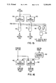
- FIG. 14 shows a schematic diagram of a fuel flow diagnosis device in accordance with the present invention.
- FIG. 15 shows a schematic diagram of a fuel pressure diagnosis device in accordance with the present invention.
- FIG. 16 shows a schematic diagram of an atomizing air flow diagnosis device in accordance with the present invention.
- FIG. 17 shows a schematic diagram of a fuel oil temperature diagnosis device in accordance with the present invention.
- FIG. 18 shows a schematic diagram of an ignitor operation diagnosis device in accordance with the present invention.
- FIG. 19 shows a schematic diagram of a combustor basket operation diagnosis device in accordance with the present invention.
- FIGS. 13 through 19 A new and novel method and apparatus for diagnosing ignition failure in a combustion turbine-generator is described in relation to FIGS. 13 through 19 herein.
- the present invention can be implemented in either software or hardware, in the preferred embodiment it is implemented in software contained in a central processing unit to be described herein.
- a central processing unit to be described herein.
- the particular program of the present invention consider first an overall description of the operating environment for the invention, namely a combustion turbine powered electric power plant.
- gas turbine electric power plant 100 which includes AC generator 102 driven by combustion or gas turbine 104.
- gas turbine 104 is preferably the W501D5 type manufactured by Westinghouse Electric Corporation.
- Community acceptance of power plant 100 is enhanced by the use of inlet and exhaust silencers 108 and 110 which are coupled respectively to inlet and exhaust ductworks 112 and 114.
- the foundation for plant 100 is approximately 106 feet long if a control station is provided for a single plant unit.
- the foundation length can be increased as indicated by the reference character 116 to provide for a master control station.
- a master control station would be warranted if additional plant units, grouped with plant 100, are to have common control.
- Micro-processor based computers and other control system circuitry in cabinet 118 provides for operation and control of power plant 100.
- cabinet 118 includes Westinghouse Distributed Processing Family (WDPF) equipment sold by Westinghouse Electric Corporation and can include two distributed processing units, an engineers console and a logger.
- An operator's cabinet 120 associated with the control cabinet 118, contains a vibration monitor, electronics for UV flame detectors, a synchroscope, and various push-button switches.
- Printer 122 and a protective relay panel 124 for sensing abnormal electric power system conditions are associated with the control cabinet 118.
- Start up or cranking power for the plant 100 is provided by a starting meter 126 which is coupled to the drive shaft of gas turbine 104 through a starting gear unit 128.
- AC motor 128 operates through a turning gear 130 and starting gear 132 to drive the gas turbine.
- turbine 104 reaches approximately 20 percent of rated speed, ignition takes place.
- a motor control center 134 is provided for operation of the various auxiliary equipment items associated with the plant 100.
- Various signals from sensor or contact elements associated with motor control center 134 and with other devices mounted on the auxiliary bed plate are transmitted for use in the control system as considered more fully in connection with FIG. 11.
- a plant battery 135 is disposed adjacent to one end of the auxiliary bed plate or skid.
- FIG. 2 One possible internal electrical power system for use with plant 100 is shown generally in FIG. 2. Once plant 100 is in operation, power generated by generator 102 is transmitted to the power system through generator breaker 136, through 13.8 KV bus 137 to a main transformer (not shown) and line breaker 138. Auxiliary power for the plant 100 is obtained from the internal power system through an auxiliary breaker 139 and an auxiliary power 480 volt bus 140.
- the generator breaker 136 serves as a synchronizing and protective disconnect device for the plant 100.
- an auxiliary power transformer 141 can be provided as shown in FIG. 3.
- a disconnect switch 142 is connected between transformer 141 and the station 13.8 KV bus 137.
- the arrangement as shown in FIG. 3 can provide for so-called black plant start up operation.
- switch gear pad 143 is included for 15 KV switch gear 144, 145 and 146, including generator breaker 136.
- the auxiliary power transformer 141 and disconnect switch 142 are also disposed on switch gear pad 143 if they are selected for use by the user.
- Excitation switch gear 150 associated with the generator excitation system is also included on the switch gear pad 143.
- the I/O circuitry of cabinet 118 accepts signals from certain sensor or contact elements associated with various switch gear pad devices.
- a pressure switch and gauge cabinet 152 is also included on the auxiliary bed plate. Cabinet 152 contains the pressure switches, gauges, regulators and other miscellaneous elements needed for gas turbine operation.
- Generator 102 including brushless exciter 154, is schematically illustrated in greater detail in FIG. 4.
- the rotating elements of generator 102 and exciter 154 are supported by a pair of bearings 158 and 160.
- Conventional generator vibration transducers 162 and 164 are coupled to bearings 158 and 160 for the purpose of generating input data for the plant control system.
- Resistance temperature detectors (RTD) 181 A-F embedded in the stator winding, are installed to measure the winding temperatures.
- Temperature detectors 159 and 161 measures bearing oil drain temperatures as indicated in FIG. 4. Signals from the temperature sensors and vibration transducers 162 and 164 are transmitted to the control system, i.e. cabinet 118.
- a permanent magnet field member 165 is rotated to induce voltage in a pilot exciter armature 166 which is coupled to a stationary AC exciter field 168 through a voltage regulator (not shown). Voltage is thereby induced in an AC exciter armature 172 formed on the exciter rotating element and it is applied across diodes mounted with fuses on a diode wheel 174 to energize a rotating field element 176 of the generator 102. Generator voltage is induced in a stationary armature winding 178 which supplies current to the power system through a generator breaker 136 when the plant 100 is synchronized and on the line.
- a transformer 180 supplies a feedback signal for the regulator 170 to control the excitation level of the exciter field 168. The signal from transformer 180 is also used as the generator megawatt signal, a control signal supplied to cabinet 118.
- gas turbine 104 in the preferred embodiment is the W 501D5, a simple cycle type having a rated speed of 3600 rpm.
- turbine 104 includes a two bearing single shaft construction, cold-end power drive and axial exhaust.
- Filtered inlet air enters multistage axial flow compressor 185 through flanged inlet manifold 183 from inlet duct work 112.
- An inlet guide vane assembly 182 includes vanes supported across the compressor inlet to provide for surge prevention particularly during start up. The angle at which all of the guide vanes are disposed in relation to the gas stream is uniform and controlled by a computer generated control signal (FIGS. 11 and 12) provided to a pneumatically operated positioning ring (not shown) coupled to the vanes in the inlet guide vane assembly 182.
- the compressor 185 is provided with a casing 184 which supports a turbine rotating element, i.e. turbine shaft, through bearings 188 and 189. Vibration transducers (FIG. 11) similar to those described in connection with FIG. 4 are provided for the gas turbine bearings 188 and 189. Compressor rotor structure 186 is secured to the turbine shaft in any known manner.
- the compressor casing 184 also supports stationary blades 190 in successive stationary blade rows along the air flow path.
- the compressor inlet air flows annularly through stages in compressor 185.
- Blades 192 mounted on the rotor 186 by means of discs 194 are appropriately designed from an aerodynamic and structural standpoint for the intended service. Both the compressor inlet and outlet air temperatures are measured by suitably supported thermocouples (FIG. 11).
- combustion system 196 comprising a total of sixteen can-annular combustors 198 conically mounted within a section 200 of the casing 184 about the longitudinal axis of the gas turbine 104.
- Combustor shell pressure is detected by a suitable sensor (FIG. 11) coupled to the compressor-combustor flow paths and provides a signal to cabinet 118 and pressure switch and gauge cabinet 152.
- Combustors 198 are shown to be cross-connected by cross-flame tubes 202 for ignition purposes in FIG. 6 (only fourteen are shown).
- a computer enabled sequenced ignition system 204 includes ignitors 206 and 208. The computer generated enabling signal will be described later.
- ignition system 204 includes a capacitance discharge ignitor and wiring to respective spark plugs which form a part of the ignitors 206 and 208.
- the spark plugs are mounted on retractable pistons within the ignitors 206 and 208 so that the plugs can be withdrawn from the combustion zone after ignition has been executed.
- the current of the signal applied to the spark plugs is measured by any suitable device and provided as feedback to the central processor (FIG. 11).
- a pair of ultraviolet (UV) flame detectors 212 and 214 are associated with each of two combustors in order to verify ignition and continued presence of combustion in the fourteen combustor baskets 198. Redundancy in flame sensing capability is especially desirable because of the hot flame detector environment.
- dual fuel nozzle 216 is mounted at the compressor end of each combustor 198.
- An oil nozzle 218 is located at the center of the dual nozzle 216 and an atomizing air nozzle 220 is located circumferentially thereabout.
- An outer gas nozzle 222 is disposed about the atomizing air nozzle 220 to complete the assembly of the fuel nozzle 216.
- fuel oil or other liquid fuel enters the oil nozzle 218 through conduit 224 while atomizing air enters manifold 226 through bore 228.
- Gaseous fuel is emitted through the nozzle 222 after flow through entry pipe 230 and manifolded/multiple nozzle arrangement 232. The regulation of fuel flow through conduits 224 and 230 will be described later.
- a portion of the compressor outlet air flow combines with the fuel in each combustor 198 to produce combustion after ignition and the balance of the compressor outlet air flow combines with the combustion products for flow through combustors 198 into a multistage reaction type turbine 234 (FIG. 5).
- the combustor casing section 200 is coupled to a turbine casing 236 through a vertical casing joint 238. No high pressure air or oil seal is required between the compressor 185 and the turbine 234.
- the turbine rotor is formed by four disc blade assemblies 240, 242, 244 and 245 mounted on a stub shaft by through bolts. Temperature sensing thermocouples (FIG. 11) are supported within the disc cavities to provide cavity temperature signals for the control system. High temperature alloy rotor blades 246 are mounted on the discs in forming the rotor assembly.
- the two support bearings 188 and 189 for turbine rotating structure are preferably so-called tilting pad bearings.
- the turbine casing 236 supports stationary blades 248 which form stationary blade rows interspersed with the rotor blade rows. Gas flow is discharged from the turbine 234 substantially at atmospheric pressure through a flanged exhaust manifold 250 attached to the outlet duct work 114.
- thermocouples are associated with the gas turbine bearing metal. Further, thermocouples for the blade flow path are supported about the inner periphery of the exhaust manifold 250 in any known manner to provide a fast response indication of blade temperature for control system usage particularly during plant start up periods. Exhaust temperature detectors are disposed in the exhaust duct work 114 primarily for the purpose of determining average exhaust temperature for system usage during load operations of the power plant 100. The significance of the above described thermocouples and other temperature detectors will be described in relation to FIG. 11.
- a fuel system 251 is provided for the delivery of gaseous fuel to the gas nozzles 222 under controlled fuel valve operation. Gas is transmitted to a diaphragm operated pressure regulating valve 254 from a gas source. It is noted at this point in the description that IEEE switch gear device numbers are generally used herein where appropriate as incorporated in American Standard C37.2-1956.
- a starting valve 256 determines gas fuel flow to the nozzles 222 at turbine speeds up to 3600 RPM.
- Valve 256 is pneumatically positioned by pneumatic actuator 261 in response to a computer generated control signal.
- valve 256 is partially open when pneumatic actuator 261 is in its fully closed position.
- Pressure regulating valve 257 provides a constant pressure and thus at ignition a constant gas flow for repeatable gas ignition in the combustion baskets.
- valve 258 opens to control gas flow to the combustion turbines maximum load output.
- a pneumatically operated trip valve 260 stops gas fuel flow under mechanical actuation if turbine overspeed reaches a predetermined level such as 110% rated speed.
- a pneumatically operated vent valve 262 allows trapped gas to be vented to the atmosphere from trip valve 260 as does on/off pneumatically operated isolation valve 264. Valves 260 and 262 are normally both open and valve 264 is normally closed. The isolation valve fuel control action is initiated by an electronic control signal applied through the pressure switch and gauge cabinet 152 (FIG. 1 and FIG. 11).
- Sensor 261 Detects gas flow and generates a signal representative of such flow for use by processor 344.
- a liquid fuel supply system 266 provides for liquid fuel flow to nozzles 218 (only eight are shown) from any suitable fuel source by means of the pumping action of motor driven main fuel pump 268.
- Pump discharge pressure is sensed for control system use by a detector 267.
- a bypass valve 271 is pneumatically operated by an electropneumatic converter 270 and a booster relay 273 to determine liquid fuel bypass flow to a return line and thereby regulate liquid fuel discharge pressure.
- a computer generated control signal provides for pump discharge pressure control, and in particular it provides for ramp pump discharge pressure control during turbine start up.
- a throttle valve 272 is held at a minimum position during the ramp pressure control action on the discharge pressure regulator valve 270.
- a pressure switch 275 indicates whether the pump 268 has pressurized intake flow.
- the pneumatically operated throttle valve 272 is positioned to control liquid fuel flow to the nozzles 218 as determined by a pneumatic actuator 274 and a booster relay 276.
- a computer generated control signal determines the converter position control action for the throttle valve 272.
- bypass valve 270 continues to operate to hold fuel discharge pressure constant.
- a mechanically actuated and pneumatically operated overspeed trip valve 278 stops liquid fuel flow in the event of turbine overspeed.
- an electrically actuated and pneumatically operated isolation valve 282 provides on/off control of liquid fuel flow to a liquid manifold 283.
- Positive displacement pumps 284 (only eight are shown) are respectively disposed in the individual liquid fuel flow paths to nozzles 218. Pumps 284 are mounted on a single shaft and they are driven by the oil flow from the manifold 283 to produce substantially equal nozzle fuel flows. Check valves 286 prevent back flow from the nozzles 218. Speed sensor 280 senses the speed of pumps 284 which is proportional to fuel flow.
- Power plant 100 is operated under the control of an integrated turbine-generator computer based control system 300 which is schematically illustrated in FIG. 11.
- the plant control system 300 embraces elements disposed in the control cabinet 118, the pressure switch and gauge cabinet 152 and other elements included in the electric power plant 100 of FIG. 1.
- control system 300 In order to start plant 100, control system 300 first requires certain status information generated by operator switches, temperature measurements, pressure switches and other sensor devices. Once it is determined that the overall plant status is satisfactory, the plant start up is initiated under programmed computer control.
- the starting sequence generally embraces starting and operating the starting motor to accelerate the gas turbine 104 from low speed, stopping the turning gear, igniting the fuel in the combustion system at about 20% rated speed, accelerating the gas turbine to about 60% rated speed and stopping the starting meter, accelerating the gas turbine 104 to synchronous speed, and loading the power after generator breaker 136 closure.
- fuel flow is stopped and the gas turbine 104 undergoes a deceleration coast down.
- the turning gear is started to drive the turbine rotating element during the cooling off period.
- a control loop arrangement 302 shown in FIG. 12 provides a representation of the preferred general control looping embodied in control system 300 (FIG. 11).
- a feed-forward characterization is preferably used to determine a representation of fuel demand needed to satisfy speed requirements. Measured process variables including turbine speed, ambient temperature and pressure, the controlled load variable or the plant megawatts, combustor shell pressure and turbine exhaust temperature are employed to limit, calibrate or control the fuel demand so that apparatus design limits are not exceeded.
- the fuel demand in the control arrangement 302 provides position control for turbine gas or liquid fuel valves, 256, 258 and 272.
- a low fuel demand selector 316 is employed to limit fuel demand by selecting from various fuel limit representations generated by each control loop. These limit representations are generated respectively by speed control 303, start ramp control 305, maximum exhaust temperature control 306, maximum megawatt control 307 and maximum instantaneous load pickup limiter 308.
- Turbine speed is controlled during normal operation by proportional, integral, differential (PID) controller 312.
- a megawatt feedback signal representative of the megawatt output of generator 102 is generated at 309 by any known technique and is provided to switch 310.
- Switch 310 provides the megawatt feedback signal to a negative input of controller 312 whenever generator breaker control 311 indicates that the generator breaker has been closed.
- a signal representative of turbine speed is generated by speed sensor 314, by any known technique, and is provided to another negative input of controller 312.
- the speed reference signal is provided to the positive input of controller 312.
- controller 312 Since controller 312 will require its inputs to sum zero and since the speed signal from sensor 314 is essentially constant after synchronization, the speed reference signal will be balanced by the megawatt signal such that the output of controller 312 will be representative of a ramping of the speed reference signal to pick up load.
- the fuel demand representation is applied to a dual fuel control 317 where the fuel demand signal is processed to produce a gas fuel demand signal for application to the gas starting and throttle valves or a liquid fuel demand signal for application to the oil throttle and pressure bypass valve or as a combination of gas and liquid fuel demand signals for application to the gas and oil valves together.
- control system 300 shown in block diagram detail in FIG. 11. It includes a general purpose computer system comprising a central processor 334 and associated input/output interfacing equipment. More specifically, the interfacing equipment for the computer 334 includes a contact closure input system 326 which scans contact or other similar signals representing the status of various plant and equipment conditions.
- Input interfacing is also provided for the computer 334 by a conventional analog input system 328 which samples analog signals from the gas turbine power plant 100 at a predetermined rate for each analog channel input and converts the signal samples to digital values for computer processing.
- a conventional printer 330 is also included and it is used for purposes including for example logging printouts as indicated by the reference character 332.
- Output interfacing generally is provided for the computer by means of a conventional contact closure output system 342 and a digital to analog system 344. Analog outputs and the contact closure output system 342 are under program control.
- the plant battery 135 considered previously in connection with FIG. 1 is also illustrated since it provides necessary supply voltages for operating the computer system, control system and other elements in the power plant 100. Battery charging is provided by a suitable charger 320.
- connections are made to the contact closure input system 326 from various turbine, protective relay, switch gear, pressure switch and gauge cabinet, and starting motor contacts.
- certain customer selected contacts 327D and miscellaneous contacts 327C such as those in the motor control center 134 are coupled to the contact closure input system 326.
- Analog/digital (A/D) input system 328 has applied to it the outputs from various plant process sensors or detectors, many of which have already been briefly considered.
- Various analog signals are generated by sensors associated with the gas turbine 104 for input to the computer system 334 where they are processed for Various purposes.
- the turbine sensors 329 A-K include multiple blade path thermocouples, disc cavity thermocouples, exhaust manifold thermocouples, bearing thermocouples, compressor inlet and discharge thermocouples, and, as designated by the block marked miscellaneous sensors 329K, oil reservoir thermocouple, bearing oil thermocouple, a main fuel inlet thermocouple, ambient air temperature sensor and an ambient air pressure sensor.
- the sensor used to measure ambient temperature can be any known device such as a thermocouple. Ambient air temperature and ambient air pressure are preferably measured at the compressor inlet.
- Combustor shell pressure sensors and turbine speed sensors also have their output signals coupled to the analog input system 328.
- a turbine support metal thermocouple is included in the miscellaneous block 329K.
- the generator temperature sensors include stator resistance temperature detectors (RTD's), inlet cooling RTD's and outlet cooling RTD's, and bearing metal thermocouples.
- Vibration sensors associated with the generator 102 and the gas turbine 104 are coupled with the analog input system 328 through the operator's console 120 where the rotating equipment vibration can be monitored.
- additional sensors which are located in the protective relay cabinet generate signals representative of various bus, line, generator and exciter electrical conditions.
- Other devices operated by contact closure outputs include the generator field breaker and the generator and line breakers 136, 138 and 139.
- the motor operated generator exciter field rheostats 171 and 177 and various devices in the motor control center 134 and the pressure switch and gauge cabinet 152 also function in response to contact closure outputs.
- the printer 330 is operated directly in a special input/output channel to central processor 334.
- FIGS. 13-19 The method and apparatus for diagnosing ignition failure conditions of the combustion turbine is more particularly shown in FIGS. 13-19. It will be recalled that several conditions are sensed in the combustion turbine and signals representative of such conditions are forwarded through A/D input system 328 and contact closure input system 326 to central processor 334. For purposes of FIG. 13, it is presumed that an airflow signal representative of the air flow through the turbine is present, such air flow having been sensed in relation to the miscellaneous sensors indicated at 329k (FIG. 11). It is further presumed that an ignition enable system has been provided by central processor 334 which invariably is presented by the contact closure system 342 to starting meter and control 204. As shown in FIG. 13, a first comparator 410 receives that air flow signal and compares that signal to a predetermined high limit. If the air flow signal exceeds the high limit an indication of such comparison is presented to AND gate 412 as a logic high signal.
- the air flow signal is also presented to comparator 414 for comparison to a low air flow limit. If the air flow signal is less than the low flow limit, an indication of such comparison is presented to AND gate 416 as a logic high signal.
- the ignition enabling signal is also shown as being presented to AND the gates 412 and 416. Consequently, if the ignition enabling signal has been received AND gate 412 will output a signal from comparator 410 if it is determined that the air flow has exceeded the high air flow limit or AND gate 416 will output the indication from comparator 414 indicating that the air flow signal is less than the low air flow limit. If ignition of the combustion turbine should fail, either one of this indication signals will readily permit a user to diagnose an air flow problem.
- AND gates 412 and 416 collectively constitute a logic member which outputs comparator indication signals when the ignition enable signal has been received.
- FIG. 14 there is shown device for diagnosing an ignition failure condition, wherein fuel flow is monitored.
- sensor 261 (FIG. 9), which is included within the group labeled miscellaneous sensors 329k (FIG. 11), generates a fuel flow signal representative of the fuel flow in the turbine.
- this fuel flow signal is presented to comparator 430 which compares the fuel flow to a high limit and generates an indication signal if the fuel flow exceeds such limit.
- the fuel flow signal is presented to comparator 432 which compares the fuel flow signal to a low limit and generates an indication signal if the fuel flow is less than such limit.
- the signals generated by comparators 430 and 432 are provided to AND gates 434 and 436, respectively.
- the ignition enable signal (block 402 in FIG. 11) and the fuel enable signal (block 305 in FIG. 12) are each provided to AND gate 438.
- the output of AND gate 438 is provided as an input to both AND gates 434 and 436.
- an output from AND gate 434 is indicative that fuel flow is too high while an output from AND gate 436 is an indication that fuel flow is too low. It will also be appreciated that the fuel flow monitoring works equally well for either the gas fuel system disclosed in FIG. 9 or for the oil fuel system disclosed in FIG. 10.
- the improper position of the fuel throttle valve can also be diagnosed.
- the outputs of AND gates 434 and 436 are each applied as inputs to OR gate 439, and as shown in FIG. 14, the output of OR gate 439 is applied to AND gates 440 and 442 as shown in FIG. 15.
- Comparator 444 is connected to the other input of AND gate 440.
- Comparator 444 is provided with the fuel pressure signal which is representative of the fuel pressure upstream from the throttle valve. Shown in FIG. 10, this signal is generated by pressure sensor 267. Comparator 444 compares the fuel pressure signal to the high limit and generates an indication or a logic high output whenever the fuel pressure signal exceeds this high limit.
- the fuel pressure signal is also provided to comparator 446
- Comparator 446 compares the fuel pressure signal to a low limit and generates an indication signal or logic high output whenever the fuel pressure signal is less than the lower limit.
- the output of comparator 446 is applied to the other input of AND gate 442.
- the output of AND gate 440 is an indication that fuel pressure is too high while an output from AND gate 442 is indicative from the fuel pressure being too low.
- the output of comparators 444 and 446 are also applied as inverted inputs to AND gate 450.
- the output from OR gate 439 in FIG. 14 is provided to the other input of AND gate 450.
- a logic high output from AND gate 450 is an indication that a fuel valve is in the wrong position. It will appreciated that AND gate 450 will generate logic high signal when it receives a logic high signal from OR gate 439 and NOT gates 448 and 449.
- FIG. 16 there is shown an apparatus for diagnosing an ignition failure condition wherein an atomizing air flow signal representative of the flow of atomizing air through the fuel nozzles is provided.
- a signal representative of the air flow through bore 228 FIG. 8
- Such an air flow sensor is included within the miscellaneous sensors noted at 329k in FIG. 11.
- the atomizing air flow signal is provided to comparators 460 and 462 in FIG. 16. These comparators are dynamic comparators in that the reference signal to which the atomizing air flow signal is compared changes with time.
- the atomizing air enable signal is provided to a reference signal generator 464.
- Signal generator 464 generates an atomizing air flow reference signal which is representative of a desired flow of atomizing air of a turbine time, i.e., at particular points in time during a turbine operating cycle.
- the output of signal generator 464 is provided as the reference input to comparators 460 and 462.
- Comparator 460 compares the actual atomization air flow signal to the reference signal and generates an output if the actual air flow signal exceeds the reference signal.
- Comparator 462 generates an output if the actual atomizing air flow signal is less than the reference signal.
- signal generator 464 includes a memory having atomizing air flow information stored therein. Upon receipt of the ignition enable signal, signal generator 464 retrieves information stored in memory and outputs such information in a time sequence flow.
- Comparator 470 compares the fuel temperature signal to a high limit and generates a logic high output if the fuel temperature is greater than the high limit.
- Comparator 472 compares the fuel temperature to a lower limit and generates a logic high output if the fuel temperature is less than this lower limit.
- the signals from comparators 470 and 472 are applied as inputs to the AND gates 474 and 476 respectively.
- the sensed speed signal i.e., generated by speed sensor 314, is provided to comparator 478. Comparator 478 determines whether turbine speed is less than a predetermined amount.
- such predetermined reference speed is approximately 3,600 rpm.
- the output of comparator 478 is provided to AND gate 480.
- the ignition enable signal is also provided to AND gate 480. It will be noted that comparator 478 is necessary so that the fuel temperature is only diagnosed during start-up operation. As will be appreciated from the above, the output of AND gate 474 is an indication that the fuel temperature is too high during the ignition process while the output of AND gate 476 is indicative of the fuel temperature being too low during the ignition process.
- each ignitor contains spark plugs which serve to ignite the fuel passing through the nozzles. See generally the discussion in relation to FIG. 6.
- a sensor in ignition system 204 senses the current provided to each spark plug and generates an ignitor signal which is representative of such current. Considering only one ignitor for the moment, the ignitor signal is passed through comparator 482 which compares the current signal to a low limit. If the current signal is less than the low limit a logic high output signal is provided to AND gate 484. The ignition enable signal is also provided to AND gate 484. An output from AND gate 484 is indicative that the current in ignitor 1 is too low. Comparator 482 and AND gate 484 are repeated for each ignitor contained in the turbine.
- the ignition on signal is provided to the hold input of sample/hold device 488.
- the failed ignition signal is provided to the hold input of sample/hold device 486. Ignition is attempted for a preset time and if no ignition has occurred, as sensed by flame detectors 212 and 214 shown in FIG. 6, a failed ignition signal is generated.
- a signal representative of the temperature in the combustion basket is provided to the sample input of each device 486 and 488.
- the output of sample hold/devices 486 and 488 are provided to difference member 490 which determines the difference between the two outputs.
- the output of difference member 490 is provided to comparator 492 which compares the difference signal to a low limit.
- the difference signal is less than the low limit comparator 492 provides a logic high output, indicative of a combustion basket flame failure.
- any difference between the signals is an indication of the ignition failure and possibly flame failure as well. Since spark plugs are only present in two of the combustion baskets out of a variable number depending on the combustion turbine model, ignition is dependent on the flame from these two baskets to propagate around to all baskets. Knowing which basket had flame and which did not is a valuable tool in determining the ignition problem. It will be noted that the device disclosed in FIG. 19 is repeated for each combustion basket contained in turbine 104.
Landscapes
- Engineering & Computer Science (AREA)
- Chemical & Material Sciences (AREA)
- Combustion & Propulsion (AREA)
- Mechanical Engineering (AREA)
- General Engineering & Computer Science (AREA)
- Control Of Turbines (AREA)
Priority Applications (5)
| Application Number | Priority Date | Filing Date | Title |
|---|---|---|---|
| US07/661,744 US5168699A (en) | 1991-02-27 | 1991-02-27 | Apparatus for ignition diagnosis in a combustion turbine |
| DE69215402T DE69215402D1 (de) | 1991-02-27 | 1992-01-28 | Einrichtung zur Zündungsdiagnose in einer Verbrennungsturbine |
| EP92101360A EP0501152B1 (en) | 1991-02-27 | 1992-01-28 | Apparatus for ignition diagnosis in a combustion turbine |
| JP07540692A JP3231826B2 (ja) | 1991-02-27 | 1992-02-26 | 燃焼タービンの点火診断装置 |
| CA002061881A CA2061881A1 (en) | 1991-02-27 | 1992-02-26 | Method and apparatus for ignition diagnosis in a combustion turbine |
Applications Claiming Priority (1)
| Application Number | Priority Date | Filing Date | Title |
|---|---|---|---|
| US07/661,744 US5168699A (en) | 1991-02-27 | 1991-02-27 | Apparatus for ignition diagnosis in a combustion turbine |
Publications (1)
| Publication Number | Publication Date |
|---|---|
| US5168699A true US5168699A (en) | 1992-12-08 |
Family
ID=24654933
Family Applications (1)
| Application Number | Title | Priority Date | Filing Date |
|---|---|---|---|
| US07/661,744 Expired - Lifetime US5168699A (en) | 1991-02-27 | 1991-02-27 | Apparatus for ignition diagnosis in a combustion turbine |
Country Status (5)
| Country | Link |
|---|---|
| US (1) | US5168699A (ja) |
| EP (1) | EP0501152B1 (ja) |
| JP (1) | JP3231826B2 (ja) |
| CA (1) | CA2061881A1 (ja) |
| DE (1) | DE69215402D1 (ja) |
Cited By (38)
| Publication number | Priority date | Publication date | Assignee | Title |
|---|---|---|---|---|
| US5551227A (en) * | 1994-12-22 | 1996-09-03 | General Electric Company | System and method of detecting partial flame out in a gas turbine engine combustor |
| US6077386A (en) * | 1998-04-23 | 2000-06-20 | Sandia Corporation | Method and apparatus for monitoring plasma processing operations |
| US6090302A (en) * | 1998-04-23 | 2000-07-18 | Sandia | Method and apparatus for monitoring plasma processing operations |
| US6123983A (en) * | 1998-04-23 | 2000-09-26 | Sandia Corporation | Method and apparatus for monitoring plasma processing operations |
| US6134005A (en) * | 1998-04-23 | 2000-10-17 | Sandia Corporation | Method and apparatus for monitoring plasma processing operations |
| US6132577A (en) * | 1998-04-23 | 2000-10-17 | Sandia Corporation | Method and apparatus for monitoring plasma processing operations |
| US6157447A (en) * | 1998-04-23 | 2000-12-05 | Sandia Corporation | Method and apparatus for monitoring plasma processing operations |
| US6165312A (en) * | 1998-04-23 | 2000-12-26 | Sandia Corporation | Method and apparatus for monitoring plasma processing operations |
| US6169933B1 (en) | 1998-04-23 | 2001-01-02 | Sandia Corporation | Method and apparatus for monitoring plasma processing operations |
| US6192826B1 (en) | 1998-04-23 | 2001-02-27 | Sandia Corporation | Method and apparatus for monitoring plasma processing operations |
| US6221679B1 (en) * | 1998-04-23 | 2001-04-24 | Sandia Corporation | Method and apparatus for monitoring plasma processing operations |
| US6223755B1 (en) | 1998-04-23 | 2001-05-01 | Sandia Corporation | Method and apparatus for monitoring plasma processing operations |
| US6246473B1 (en) | 1998-04-23 | 2001-06-12 | Sandia Corporation | Method and apparatus for monitoring plasma processing operations |
| US6247300B1 (en) * | 1999-02-26 | 2001-06-19 | Honda Giken Kogyo Kabushiki Kaisha | Gas turbine engine |
| US6254717B1 (en) | 1998-04-23 | 2001-07-03 | Sandia Corporation | Method and apparatus for monitoring plasma processing operations |
| US6261470B1 (en) | 1998-04-23 | 2001-07-17 | Sandia Corporation | Method and apparatus for monitoring plasma processing operations |
| US6269278B1 (en) | 1998-04-23 | 2001-07-31 | Sandia Corporation | Method and apparatus for monitoring plasma processing operations |
| US6275740B1 (en) | 1998-04-23 | 2001-08-14 | Sandia Corporation | Method and apparatus for monitoring plasma processing operations |
| US6419801B1 (en) | 1998-04-23 | 2002-07-16 | Sandia Corporation | Method and apparatus for monitoring plasma processing operations |
| US6537490B2 (en) * | 2001-05-30 | 2003-03-25 | M & I Heat Transfer Products Ltd. | Air inlet and outlet silencer structures for turbine |
| US6775988B2 (en) | 2002-09-13 | 2004-08-17 | Siemens Westinghouse Power Corproation | Combustion turbine having inlet air flow temperature sensor and related methods |
| US6802690B2 (en) | 2001-05-30 | 2004-10-12 | M & I Heat Transfer Products, Ltd. | Outlet silencer structures for turbine |
| US20080275620A1 (en) * | 2004-09-15 | 2008-11-06 | Hitachi, Ltd. | Ignition detecting method for gas turbine |
| US20110239914A1 (en) * | 2010-03-30 | 2011-10-06 | Yamatake Corporation | Combustion controlling device |
| US8601861B1 (en) | 2012-08-10 | 2013-12-10 | General Electric Company | Systems and methods for detecting the flame state of a combustor of a turbine engine |
| US20140260260A1 (en) * | 2013-03-12 | 2014-09-18 | Pratt & Whitney Canada Corp. | Combustor for gas turbine engine |
| US8964337B2 (en) | 2012-12-28 | 2015-02-24 | General Electric Company | Methods and systems for monitoring excitation of a generator based on a faulty status of a generator breaker |
| US9228747B2 (en) | 2013-03-12 | 2016-01-05 | Pratt & Whitney Canada Corp. | Combustor for gas turbine engine |
| US20160123593A1 (en) * | 2014-11-03 | 2016-05-05 | Alstom Technology Ltd | Can combustion chamber |
| US9366187B2 (en) | 2013-03-12 | 2016-06-14 | Pratt & Whitney Canada Corp. | Slinger combustor |
| US9746360B2 (en) | 2014-03-13 | 2017-08-29 | Siemens Energy, Inc. | Nonintrusive performance measurement of a gas turbine engine in real time |
| US9752959B2 (en) | 2014-03-13 | 2017-09-05 | Siemens Energy, Inc. | Nonintrusive transceiver and method for characterizing temperature and velocity fields in a gas turbine combustor |
| US9958161B2 (en) | 2013-03-12 | 2018-05-01 | Pratt & Whitney Canada Corp. | Combustor for gas turbine engine |
| US9976915B2 (en) | 2013-03-14 | 2018-05-22 | Siemens Energy, Inc. | Temperature measurement in a gas turbine engine combustor |
| US20200040823A1 (en) * | 2018-08-02 | 2020-02-06 | Mitsubishi Hitachi Power Systems Americas, Inc. | Active inlet turbine control |
| US10697420B2 (en) | 2017-10-23 | 2020-06-30 | Airbus Operations Sas | Ignition system of an aircraft turbine engine |
| US10788209B2 (en) | 2013-03-12 | 2020-09-29 | Pratt & Whitney Canada Corp. | Combustor for gas turbine engine |
| US20220235715A1 (en) * | 2021-01-27 | 2022-07-28 | General Electric Company | System and method for fault sensing flow components |
Families Citing this family (3)
| Publication number | Priority date | Publication date | Assignee | Title |
|---|---|---|---|---|
| ITMI20042487A1 (it) * | 2004-12-23 | 2005-03-23 | Nuovo Pignone Spa | Turbogeneratore |
| JP4745767B2 (ja) * | 2005-09-08 | 2011-08-10 | 三菱重工業株式会社 | 燃料流量制御装置及び発電システム並びに燃料流量制御方法 |
| FR2980236B1 (fr) * | 2011-09-20 | 2017-02-03 | Ge Energy Products France Snc | Procede et systeme de commande d'arret d'une turbine a gaz. |
Citations (4)
| Publication number | Priority date | Publication date | Assignee | Title |
|---|---|---|---|---|
| US2866385A (en) * | 1956-01-10 | 1958-12-30 | Northrop Aircraft Inc | Automatic jet engine starting device |
| US4308463A (en) * | 1970-10-20 | 1981-12-29 | Westinghouse Electric Corp. | System and method for operating industrial gas turbine apparatus and gas turbine electric power plants preferably with a digital computer control system |
| US4368617A (en) * | 1980-12-24 | 1983-01-18 | Toyota Jidosha Kogyo Kabushiki Kaisha | Device for controlling timing of fuel supply for starting a gas turbine engine |
| US5103629A (en) * | 1989-11-20 | 1992-04-14 | Westinghouse Electric Corp. | Gas turbine control system having optimized ignition air flow control |
Family Cites Families (8)
| Publication number | Priority date | Publication date | Assignee | Title |
|---|---|---|---|---|
| CA973722A (en) * | 1972-01-06 | 1975-09-02 | Frank L. Hubbard | Atomizing fluid control system for a gas turbine |
| US3793826A (en) * | 1972-12-08 | 1974-02-26 | Gen Motors Corp | Electronic start control circuit for gas turbine engine |
| GB2126382B (en) * | 1982-08-10 | 1986-01-08 | Nissan Motor | Gas turbine engine control system |
| US4506504A (en) * | 1983-03-31 | 1985-03-26 | Dresser Industries, Inc | Electronic fuel control system for gas turbine |
| GB8312965D0 (en) * | 1983-05-11 | 1983-06-15 | Lucas Ind Plc | Monitoring arrangement |
| GB8529223D0 (en) * | 1985-11-27 | 1986-01-02 | Lucas Ind Plc | Monitoring gas turbine engine |
| US4794755A (en) * | 1987-05-14 | 1989-01-03 | The United States Of America As Represented By The Secretary Of The Air Force | Back-up control system for F101 engine and its derivatives |
| US4872828A (en) * | 1987-09-10 | 1989-10-10 | Hamilton Standard Controls, Inc. | Integrated furnace control and control self test |
-
1991
- 1991-02-27 US US07/661,744 patent/US5168699A/en not_active Expired - Lifetime
-
1992
- 1992-01-28 EP EP92101360A patent/EP0501152B1/en not_active Expired - Lifetime
- 1992-01-28 DE DE69215402T patent/DE69215402D1/de not_active Expired - Lifetime
- 1992-02-26 CA CA002061881A patent/CA2061881A1/en not_active Abandoned
- 1992-02-26 JP JP07540692A patent/JP3231826B2/ja not_active Expired - Lifetime
Patent Citations (4)
| Publication number | Priority date | Publication date | Assignee | Title |
|---|---|---|---|---|
| US2866385A (en) * | 1956-01-10 | 1958-12-30 | Northrop Aircraft Inc | Automatic jet engine starting device |
| US4308463A (en) * | 1970-10-20 | 1981-12-29 | Westinghouse Electric Corp. | System and method for operating industrial gas turbine apparatus and gas turbine electric power plants preferably with a digital computer control system |
| US4368617A (en) * | 1980-12-24 | 1983-01-18 | Toyota Jidosha Kogyo Kabushiki Kaisha | Device for controlling timing of fuel supply for starting a gas turbine engine |
| US5103629A (en) * | 1989-11-20 | 1992-04-14 | Westinghouse Electric Corp. | Gas turbine control system having optimized ignition air flow control |
Cited By (47)
| Publication number | Priority date | Publication date | Assignee | Title |
|---|---|---|---|---|
| US5551227A (en) * | 1994-12-22 | 1996-09-03 | General Electric Company | System and method of detecting partial flame out in a gas turbine engine combustor |
| US6221679B1 (en) * | 1998-04-23 | 2001-04-24 | Sandia Corporation | Method and apparatus for monitoring plasma processing operations |
| US6077386A (en) * | 1998-04-23 | 2000-06-20 | Sandia Corporation | Method and apparatus for monitoring plasma processing operations |
| US6192826B1 (en) | 1998-04-23 | 2001-02-27 | Sandia Corporation | Method and apparatus for monitoring plasma processing operations |
| US6134005A (en) * | 1998-04-23 | 2000-10-17 | Sandia Corporation | Method and apparatus for monitoring plasma processing operations |
| US6132577A (en) * | 1998-04-23 | 2000-10-17 | Sandia Corporation | Method and apparatus for monitoring plasma processing operations |
| US6157447A (en) * | 1998-04-23 | 2000-12-05 | Sandia Corporation | Method and apparatus for monitoring plasma processing operations |
| US6165312A (en) * | 1998-04-23 | 2000-12-26 | Sandia Corporation | Method and apparatus for monitoring plasma processing operations |
| US6169933B1 (en) | 1998-04-23 | 2001-01-02 | Sandia Corporation | Method and apparatus for monitoring plasma processing operations |
| US6123983A (en) * | 1998-04-23 | 2000-09-26 | Sandia Corporation | Method and apparatus for monitoring plasma processing operations |
| US6090302A (en) * | 1998-04-23 | 2000-07-18 | Sandia | Method and apparatus for monitoring plasma processing operations |
| US6246473B1 (en) | 1998-04-23 | 2001-06-12 | Sandia Corporation | Method and apparatus for monitoring plasma processing operations |
| US6223755B1 (en) | 1998-04-23 | 2001-05-01 | Sandia Corporation | Method and apparatus for monitoring plasma processing operations |
| US20030136663A1 (en) * | 1998-04-23 | 2003-07-24 | Smith Michael Lane | Method and apparatus for monitoring plasma processing operations |
| US6254717B1 (en) | 1998-04-23 | 2001-07-03 | Sandia Corporation | Method and apparatus for monitoring plasma processing operations |
| US6261470B1 (en) | 1998-04-23 | 2001-07-17 | Sandia Corporation | Method and apparatus for monitoring plasma processing operations |
| US6269278B1 (en) | 1998-04-23 | 2001-07-31 | Sandia Corporation | Method and apparatus for monitoring plasma processing operations |
| US6275740B1 (en) | 1998-04-23 | 2001-08-14 | Sandia Corporation | Method and apparatus for monitoring plasma processing operations |
| US6419801B1 (en) | 1998-04-23 | 2002-07-16 | Sandia Corporation | Method and apparatus for monitoring plasma processing operations |
| US6247300B1 (en) * | 1999-02-26 | 2001-06-19 | Honda Giken Kogyo Kabushiki Kaisha | Gas turbine engine |
| US6802690B2 (en) | 2001-05-30 | 2004-10-12 | M & I Heat Transfer Products, Ltd. | Outlet silencer structures for turbine |
| US6537490B2 (en) * | 2001-05-30 | 2003-03-25 | M & I Heat Transfer Products Ltd. | Air inlet and outlet silencer structures for turbine |
| US6775988B2 (en) | 2002-09-13 | 2004-08-17 | Siemens Westinghouse Power Corproation | Combustion turbine having inlet air flow temperature sensor and related methods |
| US20080275620A1 (en) * | 2004-09-15 | 2008-11-06 | Hitachi, Ltd. | Ignition detecting method for gas turbine |
| US20110239914A1 (en) * | 2010-03-30 | 2011-10-06 | Yamatake Corporation | Combustion controlling device |
| US8601861B1 (en) | 2012-08-10 | 2013-12-10 | General Electric Company | Systems and methods for detecting the flame state of a combustor of a turbine engine |
| US8964337B2 (en) | 2012-12-28 | 2015-02-24 | General Electric Company | Methods and systems for monitoring excitation of a generator based on a faulty status of a generator breaker |
| US9228747B2 (en) | 2013-03-12 | 2016-01-05 | Pratt & Whitney Canada Corp. | Combustor for gas turbine engine |
| US10955140B2 (en) | 2013-03-12 | 2021-03-23 | Pratt & Whitney Canada Corp. | Combustor for gas turbine engine |
| US10788209B2 (en) | 2013-03-12 | 2020-09-29 | Pratt & Whitney Canada Corp. | Combustor for gas turbine engine |
| US9366187B2 (en) | 2013-03-12 | 2016-06-14 | Pratt & Whitney Canada Corp. | Slinger combustor |
| US9541292B2 (en) * | 2013-03-12 | 2017-01-10 | Pratt & Whitney Canada Corp. | Combustor for gas turbine engine |
| US20140260260A1 (en) * | 2013-03-12 | 2014-09-18 | Pratt & Whitney Canada Corp. | Combustor for gas turbine engine |
| US10378774B2 (en) | 2013-03-12 | 2019-08-13 | Pratt & Whitney Canada Corp. | Annular combustor with scoop ring for gas turbine engine |
| US9958161B2 (en) | 2013-03-12 | 2018-05-01 | Pratt & Whitney Canada Corp. | Combustor for gas turbine engine |
| US9976915B2 (en) | 2013-03-14 | 2018-05-22 | Siemens Energy, Inc. | Temperature measurement in a gas turbine engine combustor |
| US9746360B2 (en) | 2014-03-13 | 2017-08-29 | Siemens Energy, Inc. | Nonintrusive performance measurement of a gas turbine engine in real time |
| US9752959B2 (en) | 2014-03-13 | 2017-09-05 | Siemens Energy, Inc. | Nonintrusive transceiver and method for characterizing temperature and velocity fields in a gas turbine combustor |
| CN105570928A (zh) * | 2014-11-03 | 2016-05-11 | 阿尔斯通技术有限公司 | 筒式燃烧室 |
| US20160123593A1 (en) * | 2014-11-03 | 2016-05-05 | Alstom Technology Ltd | Can combustion chamber |
| US11149947B2 (en) * | 2014-11-03 | 2021-10-19 | Ansaldo Energia Switzerland AG | Can combustion chamber |
| US10697420B2 (en) | 2017-10-23 | 2020-06-30 | Airbus Operations Sas | Ignition system of an aircraft turbine engine |
| US20200040823A1 (en) * | 2018-08-02 | 2020-02-06 | Mitsubishi Hitachi Power Systems Americas, Inc. | Active inlet turbine control |
| US10753287B2 (en) * | 2018-08-02 | 2020-08-25 | Mitsubishi Hitachi Power Systems Americas, Inc. | Active inlet turbine control |
| US11286864B2 (en) * | 2018-08-02 | 2022-03-29 | Mitsubishi Power Americas, Inc. | Active inlet turbine control |
| US20220235715A1 (en) * | 2021-01-27 | 2022-07-28 | General Electric Company | System and method for fault sensing flow components |
| CN114810232A (zh) * | 2021-01-27 | 2022-07-29 | 通用电气公司 | 用于故障感测流动部件的系统和方法 |
Also Published As
| Publication number | Publication date |
|---|---|
| EP0501152A2 (en) | 1992-09-02 |
| EP0501152B1 (en) | 1996-11-27 |
| EP0501152A3 (en) | 1994-07-06 |
| CA2061881A1 (en) | 1992-08-28 |
| JPH0579351A (ja) | 1993-03-30 |
| DE69215402D1 (de) | 1997-01-09 |
| JP3231826B2 (ja) | 2001-11-26 |
Similar Documents
| Publication | Publication Date | Title |
|---|---|---|
| US5168699A (en) | Apparatus for ignition diagnosis in a combustion turbine | |
| KR0159930B1 (ko) | 연소 터어빈용 점화 인에이블 신호 발생 장치 및 방법 | |
| KR0159931B1 (ko) | 연소 터어빈내의 연료 흐름 제어 장치 | |
| US4283634A (en) | System and method for monitoring and controlling operation of industrial gas turbine apparatus and gas turbine electric power plants preferably with a digital computer control system | |
| US5252860A (en) | Gas turbine control system having maximum instantaneous load-pickup limiter | |
| US4039804A (en) | System and method for monitoring industrial gas turbine operating parameters and for providing gas turbine power plant control system inputs representative thereof | |
| US3978659A (en) | Bumpless transfer in shifting control command between the primary and backup control systems of a gas turbine power plant | |
| US4259835A (en) | System and method for monitoring industrial gas turbine operating parameters and for providing gas turbine power plant control system inputs representative thereof | |
| US4314441A (en) | Gas turbine power plant control apparatus including an ambient temperature responsive control system | |
| US3955359A (en) | Bearing temperature system failure detection apparatus suitable for use in power plants and like apparatus | |
| CA1072364A (en) | Stall detector for gas turbine engine | |
| US4208591A (en) | Gas turbine power plant control apparatus including a turbine load control system | |
| US4051669A (en) | Gas turbine power plant control apparatus having a multiple backup control system | |
| US4019315A (en) | Gas turbine power plant control apparatus including a temperature reset starting control system and an ignition pressure control system | |
| US4242592A (en) | Gas turbine power plant control apparatus including an ambient temperature responsive control system | |
| US5180923A (en) | Method and apparatus for downline load rejection sensing in a gas turbine control system | |
| US3943373A (en) | Gas turbine power plant control apparatus including a speed/load hold and lock system | |
| US3943371A (en) | Gas turbine power plant control apparatus including automatic load pickup | |
| US3975902A (en) | Local maintenance controller for gas turbine power plants having a primary control system | |
| EP0432570B1 (en) | Gas turbine control system having maximum instantaneous load pickup limiter | |
| US4016717A (en) | Matching response of a blade path temperature limit signal to characteristics of a gas turbine | |
| US4107542A (en) | Time delayed relay sequencer and alarm reset for a gas turbine local maintenance controller | |
| US4009567A (en) | Delayed ramping in the primary control system or local maintenance controller of a gas turbine implemented electrical power plant | |
| RU2316665C1 (ru) | Способ защиты газотурбинной установки от раскрутки силовой турбины | |
| JPH06101501A (ja) | ガスタービンの燃料制御装置およびその燃料制御方法 |
Legal Events
| Date | Code | Title | Description |
|---|---|---|---|
| AS | Assignment |
Owner name: WESTINGHOUSE ELECTRIC CORPORATION, WESTINGHOUSE BU Free format text: ASSIGNMENT OF ASSIGNORS INTEREST.;ASSIGNORS:MC CARTY, WILLIAM L.;WESCOTT, KERMIT R.;TYLER, PAUL J.;AND OTHERS;REEL/FRAME:005632/0799;SIGNING DATES FROM 19910123 TO 19910218 |
|
| STCF | Information on status: patent grant |
Free format text: PATENTED CASE |
|
| FEPP | Fee payment procedure |
Free format text: PAYOR NUMBER ASSIGNED (ORIGINAL EVENT CODE: ASPN); ENTITY STATUS OF PATENT OWNER: LARGE ENTITY |
|
| FPAY | Fee payment |
Year of fee payment: 4 |
|
| AS | Assignment |
Owner name: SIEMENS WESTINGHOUSE POWER CORPORATION, FLORIDA Free format text: ASSIGNMENT NUNC PRO TUNC EFFECTIVE AUGUST 19, 1998;ASSIGNOR:CBS CORPORATION, FORMERLY KNOWN AS WESTINGHOUSE ELECTRIC CORPORATION;REEL/FRAME:009605/0650 Effective date: 19980929 |
|
| FEPP | Fee payment procedure |
Free format text: PAYER NUMBER DE-ASSIGNED (ORIGINAL EVENT CODE: RMPN); ENTITY STATUS OF PATENT OWNER: LARGE ENTITY Free format text: PAYOR NUMBER ASSIGNED (ORIGINAL EVENT CODE: ASPN); ENTITY STATUS OF PATENT OWNER: LARGE ENTITY |
|
| FPAY | Fee payment |
Year of fee payment: 8 |
|
| FPAY | Fee payment |
Year of fee payment: 12 |
|
| AS | Assignment |
Owner name: SIEMENS POWER GENERATION, INC., FLORIDA Free format text: CHANGE OF NAME;ASSIGNOR:SIEMENS WESTINGHOUSE POWER CORPORATION;REEL/FRAME:016996/0491 Effective date: 20050801 |
|
| AS | Assignment |
Owner name: SIEMENS ENERGY, INC., FLORIDA Free format text: CHANGE OF NAME;ASSIGNOR:SIEMENS POWER GENERATION, INC.;REEL/FRAME:022482/0740 Effective date: 20081001 Owner name: SIEMENS ENERGY, INC.,FLORIDA Free format text: CHANGE OF NAME;ASSIGNOR:SIEMENS POWER GENERATION, INC.;REEL/FRAME:022482/0740 Effective date: 20081001 |