US5160132A - Sheet conveying/sorting system - Google Patents
Sheet conveying/sorting system Download PDFInfo
- Publication number
- US5160132A US5160132A US07/774,867 US77486791A US5160132A US 5160132 A US5160132 A US 5160132A US 77486791 A US77486791 A US 77486791A US 5160132 A US5160132 A US 5160132A
- Authority
- US
- United States
- Prior art keywords
- conveying
- conveying means
- sheets
- upstream
- downstream
- Prior art date
- Legal status (The legal status is an assumption and is not a legal conclusion. Google has not performed a legal analysis and makes no representation as to the accuracy of the status listed.)
- Expired - Lifetime
Links
- 238000011144 upstream manufacturing Methods 0.000 claims abstract description 81
- 238000000926 separation method Methods 0.000 claims abstract description 30
- 230000002093 peripheral effect Effects 0.000 claims description 2
- 238000004519 manufacturing process Methods 0.000 description 6
- 238000009434 installation Methods 0.000 description 3
- 238000005299 abrasion Methods 0.000 description 2
- 230000000694 effects Effects 0.000 description 2
- 239000011888 foil Substances 0.000 description 2
- 239000002184 metal Substances 0.000 description 2
- 238000004891 communication Methods 0.000 description 1
- 238000010276 construction Methods 0.000 description 1
- 230000003111 delayed effect Effects 0.000 description 1
- 238000012986 modification Methods 0.000 description 1
- 230000004048 modification Effects 0.000 description 1
Images


Classifications
-
- B—PERFORMING OPERATIONS; TRANSPORTING
- B65—CONVEYING; PACKING; STORING; HANDLING THIN OR FILAMENTARY MATERIAL
- B65H—HANDLING THIN OR FILAMENTARY MATERIAL, e.g. SHEETS, WEBS, CABLES
- B65H29/00—Delivering or advancing articles from machines; Advancing articles to or into piles
- B65H29/58—Article switches or diverters
- B65H29/60—Article switches or diverters diverting the stream into alternative paths
-
- B—PERFORMING OPERATIONS; TRANSPORTING
- B65—CONVEYING; PACKING; STORING; HANDLING THIN OR FILAMENTARY MATERIAL
- B65H—HANDLING THIN OR FILAMENTARY MATERIAL, e.g. SHEETS, WEBS, CABLES
- B65H29/00—Delivering or advancing articles from machines; Advancing articles to or into piles
- B65H29/16—Delivering or advancing articles from machines; Advancing articles to or into piles by contact of one face only with moving tapes, bands, or chains
-
- B—PERFORMING OPERATIONS; TRANSPORTING
- B65—CONVEYING; PACKING; STORING; HANDLING THIN OR FILAMENTARY MATERIAL
- B65H—HANDLING THIN OR FILAMENTARY MATERIAL, e.g. SHEETS, WEBS, CABLES
- B65H29/00—Delivering or advancing articles from machines; Advancing articles to or into piles
- B65H29/24—Delivering or advancing articles from machines; Advancing articles to or into piles by air blast or suction apparatus
- B65H29/241—Suction devices
- B65H29/242—Suction bands or belts
-
- B—PERFORMING OPERATIONS; TRANSPORTING
- B65—CONVEYING; PACKING; STORING; HANDLING THIN OR FILAMENTARY MATERIAL
- B65H—HANDLING THIN OR FILAMENTARY MATERIAL, e.g. SHEETS, WEBS, CABLES
- B65H29/00—Delivering or advancing articles from machines; Advancing articles to or into piles
- B65H29/26—Delivering or advancing articles from machines; Advancing articles to or into piles by dropping the articles
- B65H29/32—Delivering or advancing articles from machines; Advancing articles to or into piles by dropping the articles from pneumatic, e.g. suction, carriers
-
- B—PERFORMING OPERATIONS; TRANSPORTING
- B65—CONVEYING; PACKING; STORING; HANDLING THIN OR FILAMENTARY MATERIAL
- B65H—HANDLING THIN OR FILAMENTARY MATERIAL, e.g. SHEETS, WEBS, CABLES
- B65H29/00—Delivering or advancing articles from machines; Advancing articles to or into piles
- B65H29/66—Advancing articles in overlapping streams
-
- B—PERFORMING OPERATIONS; TRANSPORTING
- B65—CONVEYING; PACKING; STORING; HANDLING THIN OR FILAMENTARY MATERIAL
- B65H—HANDLING THIN OR FILAMENTARY MATERIAL, e.g. SHEETS, WEBS, CABLES
- B65H33/00—Forming counted batches in delivery pile or stream of articles
- B65H33/12—Forming counted batches in delivery pile or stream of articles by creating gaps in the stream
-
- B—PERFORMING OPERATIONS; TRANSPORTING
- B65—CONVEYING; PACKING; STORING; HANDLING THIN OR FILAMENTARY MATERIAL
- B65H—HANDLING THIN OR FILAMENTARY MATERIAL, e.g. SHEETS, WEBS, CABLES
- B65H2404/00—Parts for transporting or guiding the handled material
- B65H2404/20—Belts
- B65H2404/25—Driving or guiding arrangements
- B65H2404/254—Arrangement for varying the guiding or transport length
-
- B—PERFORMING OPERATIONS; TRANSPORTING
- B65—CONVEYING; PACKING; STORING; HANDLING THIN OR FILAMENTARY MATERIAL
- B65H—HANDLING THIN OR FILAMENTARY MATERIAL, e.g. SHEETS, WEBS, CABLES
- B65H2406/00—Means using fluid
- B65H2406/30—Suction means
- B65H2406/32—Suction belts
- B65H2406/323—Overhead suction belt, i.e. holding material against gravity
Definitions
- the present invention relates to a sheet conveying and sorting system and, in particular, to such sheet conveying and sorting system which sorts sheets such as paper, film, metal foil or the like and collects the sheets by a given number of sheets (which can also be referred to as a package unit of sheets).
- a sheet conveying/sorting system which sorts the sheets by the package unit includes mainly the following types:
- a first type is a sheet conveying/sorting system which is shown in FIG. 12.
- a long web 12 sent out from a roll 10 is cut by a cutter 14 into predetermined length of sheets 16.
- the thus cut sheets 16 are then sorted by a sheet sorting gate 18 of the sheet included in the sheet conveying/sorting system into two passages, that is, an upper conveying passage 20 and a lower conveying passage 22.
- the sheets 16 can be collected by the package units into an upper collecting part 24 and a lower collecting part 26 alternately.
- the sheets are gated out at the reduced sheet cutting speed to a reject gate provided downstream of a cutting part to thereby obtain a switch time for sorting the sheets, and the sorted sheets are then collected by the package units.
- a third type of sheet conveying/sorting system includes in the collecting part thereof a fork for sorting the sheets and the third type system is able to sort the sheets by the package units by advancing and retreating the fork.
- a stopper in the middle of a conveying passage, the sheets are held by and between the stopper and the conveying passage, the sheets are stopped so the distance between the sheets being conveyed on and the sheets being stopped is increased, and then the sheets are sorted by the package units (see Japanese Patent Application Laid-Open (Tokkai) No. 1-294164).
- a fifth type of sheet conveying/sorting system includes an inside conveyor and an outside conveyor which is disposed along the outer periphery of the inside conveyor. And, a holding conveyor is disposed above the outside conveyor. While sheets being moved are being held by and between the outside and holding conveyors, the speed of the inside conveyor is increased to widen the distance between the sheets being held and the sheets being carried on the inside conveyor, so that the sheets can be sorted by the package units (see Japanese Patent Application Laid-Open (Tokkai) No. 2-127355).
- the gating-out of the sheets leads to the lowered rate of the quantity of sheets that is theoretically expected in a production process and at the same time, because the sheets are sorted by reducing the sheet cutting speed, a production efficiency is lowered as well.
- the third and fourth types of sheet conveying/sorting systems because the third type sorts the sheets by use of the fork, and because the fourth type sorts the sheets while the sheets are being held by and between the stopper and conveying passage, there is a possibility that the sheet conveying attitude or the positional relationship between the sheets can be disturbed or that, when the sheet has a soft surface, the sheet surface can be abraded.
- these types of systems are disadvantageous in that the sheets conveying operation thereof is not stable.
- the fifth type of sheet conveying/sorting system since the leading end of the sheet held by and between the inside and holding conveyors may be rubbed against the inside conveyor, the soft sheet surface can be abraded. Also, the fifth type system finds it hard to adapt itself to a small package.
- the present invention aims at eliminating the drawbacks found in the above-mentioned conventional sheet conveying/sorting systems.
- a sheet conveying/sorting system which sorts a plurality of sheets being successively conveyed into a plurality of groups or package units each consisting of a given number of sheets
- the sheet conveying/sorting system comprising: downstream conveying means capable of changing the conveying speed of the sheets; upstream conveying means disposed upstream of the downstream conveying means and including a conveying passage, the conveying passage of the upstream conveying means being expandable and contractible along the conveying passage of the downstream conveying means; sucking/conveying means disposed above the conveying passages of the upstream and downstream conveying means for attracting the sheets and conveying the sheets along the conveying passages; and control means for counting the number of the sheets being conveyed and outputting a separation signal when the number of the sheets being conveyed reaches a given number to thereby allow the sucking/conveying means to execute its attracting operation and to increase the conveying speed of the downstream conveying means over the conveying speed of the up
- a separation signal is output from the control means.
- the separation signal expands the conveying passage of the upstream conveying means as well as allows the sucking/conveying means to perform its attracting operation to thereby attract the sheets in the conveying passage of the upstream conveying means.
- the separation signal allows the sucking/conveying means to move following the expansion of the upstream conveying means.
- the separation signal makes the conveying speed of the downstream conveying means faster than the conveying speed of the upstream conveying means. The difference between the conveying speeds of the downstream and upstream conveying means causes the sheets in the conveying passage of the downstream conveying means to be separated from the sheets attracted by the sucking/conveying means.
- a return signal is output from the control means.
- the return signal contracts the expanded conveying passage of the upstream conveying means to return its original length before it is expanded as well as stops the attracting operation of the sucking/conveying means.
- the return signal returns the conveying speed of the downstream conveying means to the speed equal to the conveying speed of the upstream conveying means. In this manner, the present sheet conveying/sorting system is returned to its original state and the sheets are conveyed successively from the upstream conveying means to the downstream conveying means.
- the above-mentioned steps are sequentially repeated so that the sheets can be sorted by the target number of sheets, that is, by the package units of sheets.
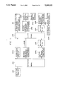
- FIG. 1 is a perspective view of a sheet conveying/sorting system according to the invention
- FIG. 2 is an enlarged view of the main portions of attracting/conveying means used in the present sheet conveying/sorting system
- FIG. 3(A) is an enlarged view of the main portions of the present sheet conveying/sorting system, illustrating a state in which the present system is not performing an operation of separating the sheets;
- FIG. 3(B) is a front view of the main portions of the present sheet conveying/sorting system in the state shown in FIG. 3(A);
- FIG. 4(A) is an enlarged view of the main portions of the present sheet conveying/sorting system, illustrating a state in which the present system starts the operation of separating the sheets;
- FIG. 4(B) is a front view of the main portions of the present sheet conveying/sorting system in the state shown in FIG. 4(A);
- FIG. 5 is a front view of the present sheet conveying/sorting system, illustrating a state in which the present system has separated the sheets;
- FIG. 6 is a flow chart to show the operation states of a sheet conveying/sorting system according to the invention.
- FIG. 7 is a perspective view of another embodiment of a sheet conveying/sorting system according to the invention.
- FIG. 8 (A) is an enlarged view of the main portions of a second embodiment of a sheet conveying/sorting system according to the invention, illustrating a state in which the embodiment is not performing its sheet separation operation;
- FIG. 8 (B) is a front view of FIG. 8 (A);
- FIG. 9 (A) is an enlarged view of the main portions of the second embodiment according to the invention, illustrating a state in which the second embodiment starts its sheet separation operation;
- FIG. 9 (B) is a front view of FIG. 9 (A);
- FIG. 10 is a front view of the second embodiment of a sheet conveying/sorting system according to the invention, illustrating a state in which the second embodiment has separated the sheets from each other;
- FIG. 11 is a flow chart of the operating states of the second embodiment according to the invention.
- FIG. 12 is a front view of a sheet conveying/sorting system according to the prior art.
- FIG. 1 there is shown a perspective view of a sheet conveying/sorting system 50 constructed in accordance with the present invention.
- the sheet conveying/sorting system 50 comprises downstream conveying means (separating conveyor means) 52, upstream conveying means (movable conveyor means) 54, sucking/conveying means (suction conveyor means) 56, control means 58 (shown in FIGS. 2, 3 and 5) and the like.
- the downstream conveying means 52 includes fixed pulleys 60A, 60B, 60C and 60D around which a plurality of endless belts 62 are stretched at regular intervals and according to the width of the sheet conveying/sorting system 50. These belts 62 can be moved clockwise in FIG. 1 by first drive means (not shown) through the pulleys and are connected so that the moving speeds of the belts 62 can be changed. And, the portion of the belt 62 that is stretched horizontally by the fixed pulleys 60A, 60B forms a conveying passage 62A.
- the upstream conveying means 54 includes a movable pulleys 64A, 64B and fixed pulleys 66A, 66B, 66C and 66D, around which pulleys a plurality of belts 68 are stretched. These belts 68 are respectively arranged at the same intervals as in the respective belts 62 of the downstream conveying means 52.
- the belts 68 are connected through the belts to second drive means (not shown) in such a manner that they can be rotated clockwise in FIG. 1.
- the movable pulleys 64A, 64B are constructed in such a manner that they can be moved along the conveying passage 62A of the downstream conveying means 52. And, the portions of the belts 68 that are stretched horizontally around by the movable pulley 64A and fixed pulley 66B form the conveying passage 68A of the upstream conveying means 54.
- the conveying passage 68A is disposed in parallel to the conveying passage 62A of the downstream conveying means 52.
- the sucking/conveying means 56 includes fixed pulleys 72A, 72B and 72C which are disposed above the downstream conveying means 52 and upstream conveying means 54.
- a plurality of endless belts 74 are stretched substantially in a triangle around the fixed pulleys 72A, 72B and 72C.
- the belts 74 are respectively connected to third drive means (not shown) in such a manner that they can be moved counter-clockwise in FIG. 1.
- third drive means not shown
- a suction box 76 in contact with the upper surfaces of the respective belts 74.
- the suction box 76 is constructed in such a manner that it is in communication with a suction pump (not shown). Also, the suction box 76 has a suction port (not shown) the surface thereof which is in contact with the belts 74. For this reason, when the belts 74 are put into operation and the holes 74A, 74A, are brought into contact with the suction box 76, then the holes 74A, 74A, . . . of the belts 74 provide suction ports, respectively.
- the control means 58 includes a detector 58A which, as shown in FIG. 3(A), is disposed above the upstream conveying means 54 and on the upstream side of the fixed pulley 72B of the sucking/conveying means 56.
- the detector 58A counts the number of sheets 80, 80, . . . conveyed and, when the number of sheets 80 conveyed reaches a target number, that is, a package unit number, outputs a separation signal.
- the separation signal output from the detector 58A is input through the control means 58 into the downstream conveying means 52, upstream conveying means 54 and sucking/conveying means 56.
- the separation signal controls the second drive means of the upstream conveying means 54 to move the movable pulleys 64A, 64B in a conveying direction at the same speed as the speed of the subject conveying means.
- the separation signal controls the third drive means of the sucking/conveying means 56 to suck in air through the holes 74A, 74A, . . . of the belts 74 in contact with the suction box 76 and also controls the first conveying means of the downstream conveying means 52 to make the conveying speed thereof faster than the conveying speed of the upstream conveying means 54.
- control means 58 outputs a return signal after a return detector 58B (see FIG. 5) disposed downstream detects the pulleys 64A, 64B.
- the return signal causes the movable pulleys 64A, 64B of the upstream conveying means 54 to move upstream and, after the movable pulleys 64A, 64B are detected by the given position detector 58D (see FIG. 5), the return signal causes the pulleys 64A, 64B to stop their movements, so that the movable pulleys 64A, 64B can be returned to their respective original positions.
- the returns signal returns the increased conveying speed of the downstream conveying means 52 to the conveying speed of the upstream conveying means 54.
- the holes 74A, 74A, . . . of the belts 74 of the sucking/conveying means 56 are moved from the lower portion of the suction box 76 to the upper portion thereof, which causes the sucking/conveying means 56 to stop its sucking operation.
- a given position stop detector 58C included in the control means 58 detects position determining holes 75 formed in the belts 74 of the sucking/conveying means 56 and outputs a stop signal.
- the third drive means is caused to stop in accordance with the stop signal. For this reason, the belts 74 of the sucking/conveying means 56 locate the holes 74A, 74A, . . . at the wait positions of the next step before they are stopped.
- the sheets 80, 80, cut in the previous step are respectively overlapped on their adjoining sheets 80 and are then guided to the conveying passage 68A of the upstream conveying means 54.
- These sheets 80, 80 are then guided from the conveying passage 68A to the conveying passage 62A of the downstream conveying means 52, and are conveyed by the conveying passage 62A to a sheet collecting part (not shown) sequentially, so that the sheets 80, 80, . . . are collected in the sheet collecting part (Step 100).
- the detector 58A of the control means 58 counts the number of sheets 80, 80, . . . conveyed and, when the number of sheets conveyed reaches a target number, the detector 58A outputs signal to the effect to the control means 58.
- the control means 58 On receiving the signal from the detector 58A, the control means 58 outputs a separation signal (Step 102).
- the separation signal moves the movable pulleys 64A, 64B of the upstream conveying means 54 in a right direction along the conveying passage 62A of the downstream conveying means 52 at the same speed as the conveying speed of the upstream conveying means 54. For this reason, the conveying passage 68A of the upstream conveying means 54 is expanded in the right direction (Step 104B).
- the belt 74 of the sucking/conveying means 56 is started to rotate counter clockwise at the same speed as the speed of the upstream conveying means (Step 104C) and the holes 74A, 74A, . . . of the belt 74 are moved to the lower portion of the suction box 76, so that the leading end portions of the sheets 80, 80, . . . being conveyed in the conveying passage 68A of the upstream conveying means 54 are sucked to the belt 74.
- the sheet 80A in the conveying passage 6BA and the sheet 80B in the conveying passage 62A of the downstream conveying means 52 are separated from each other (Step 106).
- the separation signal makes the conveying speed of the downstream conveying means 52 faster than the conveying speed of the upstream conveying means 54, so that the separated sheet 80A and sheet 80B are moved apart from each other, as shown in FIG. 4, (Step 104A).
- the return detector 58B of the control means 58 outputs a return signal (Step 108).
- the return signal causes the movable pulleys 64A, 64B of the upstream conveying means 54 to move upstream and, after the movable pulleys 64A, 64B are detected by the given position detector 58D, the return signal causes the movable pulleys 64A, 64B to stop its movements, so that the movable pulleys 64A, 64B can be returned to their respective original positions.
- the length of the conveying passage 68A of the upstream conveying means 54 is contracted to its original length (Step 110A, 110B, 110C).
- the holes 74A, 74A, . . . of the belt 74 of the sucking/conveying means 56 are moved from the lower portion of the suction box 76 up to the upper portion thereof and are stopped at their given positions in accordance with a signal from the given position detector 58C, so that the suction of the sheets 80, 80, . . . to the belt 74 is removed (Steps 112A, 112B, 112C).
- the return signal returns the conveying speed of the downstream conveying means 52 to the speed equal to the conveying speed of the upstream conveying means 54 (Step 114). For this reason, the sheets 80, 80, . . . are successively conveyed from the upstream conveying means 54 to the downstream conveying means 52.
- the sheets are sorted by the target numbers and thus the sheets can be stably sorted by the package units in a sheet collecting part in the following step.
- the suction box may be moved to thereby separate the sheets 80, 80, . . . from each other.
- a sheet conveying/sorting system 150 comprises downstream conveying means (separating conveyor means) 52, upstream conveying means (movable conveyor means) 54, sucking/conveying means (movable suction box means) 156, control means 58 (shown in FIG. 8, FIG. 10) and the like.
- a suction box 171 of the sucking/conveying means 156 is disposed above the downstream conveying means 52 and upstream conveying means 54 and liner bearings 172, 172 are mounted to and supported by the two ends of the suction box 171.
- the suction box 171 is structured such that is can be moved along a conveying passage 62A of the downstream conveying means 52 similarly to the upstream conveying means 54.
- the suction box 171 there are formed a large number of holes (not shown) on the lower surface of the suction box 171, and the holes are adapted to communicate with a pump (not shown) so as to provide a suction port.
- the control means 58 includes a detector 58A which, as shown in FIG. 8(A), is disposed above the upstream conveying means 54 and on the upstream side of the sucking/conveying means 156.
- the detector 58A counts the number of sheets 80, 80, . . . conveyed and, when the number of sheets 80 conveyed reaches a target number, that is, a package unit number, outputs a separation signal.
- the separation signal output from the detector 58A is input through the control means 58 into the downstream conveying means 52, upstream conveying means 54 and sucking/conveying means 156.
- the separation signal controls the second drive means of the upstream conveying means 54 to move the movable pulleys 64A, 64B in a conveying direction at the same speed as the speed of the subject conveying means.
- the separation signal controls the third drive means of the sucking/conveying means 156 to suck in air through the numerous holes formed on the suction box 171 and also to move the suction box 171 in the conveying direction at the same speed as that of the upstream conveying means 54.
- the separation signal controls the first conveying means of the downstream conveying means 52 to the make the conveying speed thereof faster than the conveying speed of the upstream conveying means 54.
- control means 58 outputs a return signal after a return detector 58B (see FIG. 10) disposed downstream detects the movable pulleys 64A, 64B.
- the return signal returns the movable pulleys 64A, 64B of the upstream conveying means 54 and at the same time returns the increased conveying speed of the downstream conveying means 52 to the conveying speed of the upstream conveying means 54.
- the return signal causes the suction box 171 of the sucking/conveying means 156 to stop its sucking operation and to return to its original position.
- a given position stop detector 58C, 58D see FIG.
- control means 58 included in the control means 58 detects the movable pulleys 64A, 64B of the upstream conveying means 54 and the suction box 171 of the sucking/conveying means 156 and outputs a stop signal.
- the second and third drive means moving in the conveying direction are caused to stop in accordance with the stop signal.
- the sheets 80, 80, . . . cut in the previous step are respectively overlapped on their adjoining sheets 80 and are then guided to the conveying passage 68A of the upstream conveying means 54.
- These sheets 80, 80, . . . are then guided from the conveying passage 68A to the conveying passage 62A of the downstream conveying means 52, and are conveyed by the conveying passage 62A to a sheet collecting part (not shown) sequentially, so that the sheets 80, 80, . . . are collected in the sheet collecting part (Step 200).
- the detector 58A of the control means 58 counts the number of sheets 80, 80, . . . conveyed and, when the number of sheets conveyed reaches a target number, the detector 58A outputs a signal to the effect to the control means 58.
- the control means 58 On receiving the signal from the detector 58A, the control means 58 outputs a separation signal (Step 202).
- the separation signal moves the movable pulleys 64A, 64B of the upstream conveying means 54 in a right direction along the conveying passage 62A of the downstream conveying means 52 at the same speed as the conveying speed of the upstream conveying means 54. For this reason, the conveying passage 68A of the upstream conveying means 54 is expanded in the right direction (Step 204B).
- the suction box 171 of the sucking/conveying means 156 is started to move in a right direction along the conveying Passage 62A of the downstream conveying means 52 at the same speed as that of the upstream conveyor (Step 204C), and at the same time the front end portions of the sheets 80, 80, being conveyed in the conveying passage 68A of the upstream conveying means 54 are sucked by the suction port in the lower surface of the suction box 171.
- the sheet 80A in the conveying passage 68A can be separated from the sheet 80B in the conveying passage 62A of the downstream conveying means 52 (Step 206).
- the separation signal makes the conveying speed of the downstream conveying means 52 faster than the conveying speed of the upstream conveying means 54, so that the separated sheet 80A and 80B are moved apart from each other, as shown in FIG. 9, (Step 204A).
- the return detector 58B of the control means 58 outputs a return signal (Step 208).
- This return signal return the movable pulleys 64A, 64B of the upstream conveying means 54 to their respective original positions, so that the length of the conveying passage 68A of the upstream conveying means 54 is contracted and returned to its original length in accordance with a signal from the given position detector 58C (Steps 210A, 210B, 210C).
- the suction of the suction box 171 of the sucking/conveying means 156 is removed, so that the suction box 171 is moved upwardly from the sucking position thereof and is stopped at its original position in accordance with a signal from the given position detector 58D (Step 212A, 212B, 212C, 212D).
- the return signal causes the conveying speed of the downstream conveying means 52 to return to the same speed as the conveying speed of the upstream conveying means 54 (Step 214).
- the sheets 80, 80, . . . are conveyed successively from the upstream conveying means 54 to the downstream conveying means 52.
- the sheets can be sorted by a target number of sheets and thus the sheets can be sorted by a package unit in a sheet collecting part in a following step.
- the invention is not limited to the above, but other structures may be employed.
- air may be blown separated the portion from the downstream side, or the downstream conveying means 52 may be constructed in the form of a suction conveyor in order to improve the separation between the sheets.
- the detector 58B may be moved to the upstream side so that the speeds of the upstream conveying means 54 and sucking/conveying means 56, 156 can be increased after they return to their respective original positions. This structure is able to cope with a small package unit.
- the manufacturing costs can be reduced and the installation space of the whole system can also be minimized. Also, due to the fact that the sheet gating-out and cutting speeds need not be delayed, the theoretically expected rate of the sheets and a production efficiency are not be lowered. Further, because the sheets can be sorted without using any fork or stopper, it is possible to prevent the sheets from being disturbed in conveying as well as to prevent the sheets against abrasions.
Landscapes
- Engineering & Computer Science (AREA)
- Mechanical Engineering (AREA)
- Separation, Sorting, Adjustment, Or Bending Of Sheets To Be Conveyed (AREA)
- Forming Counted Batches (AREA)
- Sorting Of Articles (AREA)
- Specific Conveyance Elements (AREA)
- Attitude Control For Articles On Conveyors (AREA)
- Belt Conveyors (AREA)
- Intermediate Stations On Conveyors (AREA)
- Delivering By Means Of Belts And Rollers (AREA)
Abstract
Description
Claims (5)
Applications Claiming Priority (4)
| Application Number | Priority Date | Filing Date | Title |
|---|---|---|---|
| JP2-275717 | 1990-10-15 | ||
| JP27571790 | 1990-10-15 | ||
| JP3-254949 | 1991-10-02 | ||
| JP3254949A JP2601959B2 (en) | 1990-10-15 | 1991-10-02 | Sheet transport sorting device |
Publications (1)
| Publication Number | Publication Date |
|---|---|
| US5160132A true US5160132A (en) | 1992-11-03 |
Family
ID=26541932
Family Applications (1)
| Application Number | Title | Priority Date | Filing Date |
|---|---|---|---|
| US07/774,867 Expired - Lifetime US5160132A (en) | 1990-10-15 | 1991-10-11 | Sheet conveying/sorting system |
Country Status (4)
| Country | Link |
|---|---|
| US (1) | US5160132A (en) |
| EP (1) | EP0481386B1 (en) |
| JP (1) | JP2601959B2 (en) |
| DE (1) | DE69116074T2 (en) |
Cited By (9)
| Publication number | Priority date | Publication date | Assignee | Title |
|---|---|---|---|---|
| US5288067A (en) * | 1992-02-07 | 1994-02-22 | Man Roland Druckmaschinen Ag | Method and apparatus for conveying an imbricated stream of sheets to a sheet processing machine |
| US5626336A (en) * | 1992-02-20 | 1997-05-06 | Fosber S.P.A. | Storage and stacking device for sheets of laminar material |
| US20030116476A1 (en) * | 2000-05-16 | 2003-06-26 | Aldo Perobelli | Device for the separation of a series of products that are superposed in a scale-like fashion |
| US20050012261A1 (en) * | 2003-07-16 | 2005-01-20 | Gafner Jeffrey U. | Dual modulated vacuum shingler |
| US6883409B1 (en) * | 1999-09-21 | 2005-04-26 | Jagenberg Querschneider Gmbh | Device for cross/cutting material strips, in particular cardboard strips |
| US20090212497A1 (en) * | 2008-02-26 | 2009-08-27 | Duplo Seiko Corporation | Paper ejecting device |
| WO2012055761A1 (en) * | 2010-10-28 | 2012-05-03 | Böwe Systec Gmbh | Apparatus and method for buffer-storing a plurality of goods or goods groups, and paper handling system having said apparatus |
| US20150210500A1 (en) * | 2011-09-09 | 2015-07-30 | Vits International, Inc. | Stacker |
| US11352232B2 (en) * | 2017-06-14 | 2022-06-07 | Bw Papersystems Stuttgart Gmbh | Apparatus and method for positionally defined transport of sheets |
Families Citing this family (11)
| Publication number | Priority date | Publication date | Assignee | Title |
|---|---|---|---|---|
| JP2886061B2 (en) * | 1993-10-29 | 1999-04-26 | 財団法人化学及血清療法研究所 | Method and composition for stabilizing protein C or activated protein C |
| BE1012090A3 (en) * | 1998-07-27 | 2000-04-04 | Europ Patentverwertung | Device and method for creating a space in a conveyance series of overlapping products |
| DE19851371A1 (en) * | 1998-11-07 | 2000-05-11 | Bielomatik Leuze & Co | Device for creating a gap in a shingled arc stream |
| JP2001315933A (en) * | 2000-05-12 | 2001-11-13 | Ishida Co Ltd | Conveyor device |
| JP4829427B2 (en) * | 2001-06-11 | 2011-12-07 | 学校法人立命館 | Paper sheet conveying apparatus and paper sheet conveying system |
| DE102008025667A1 (en) * | 2008-05-28 | 2009-12-10 | E.C.H. Will Gmbh | Conveyor for sheet layers and method for forming and conveying a scale flow from sheet layers |
| US7588139B1 (en) * | 2008-08-12 | 2009-09-15 | Campbell Iii William Arthur | Conveyor assembly |
| CN106494848B (en) * | 2016-11-17 | 2018-11-20 | 中天建扬物流技术成都有限公司 | Cigarette Sorting System order board automatic recycling device |
| EP3941733B1 (en) * | 2019-03-18 | 2024-01-24 | W.H. Leary Co | System and method for zero defect carton rejection |
| DE102020120344B4 (en) * | 2020-07-31 | 2024-01-18 | Werner Bachmann | SEPARATOR FOR SHADE STREAMS |
| DE102020121243A1 (en) * | 2020-08-12 | 2022-02-17 | MM Engineering GmbH | Device and method for carrying out a packaging step when packaging flat cardboard goods which are designed as folding boxes |
Citations (9)
| Publication number | Priority date | Publication date | Assignee | Title |
|---|---|---|---|---|
| DE649326C (en) * | 1936-06-20 | 1937-08-20 | Julius Fischer Fa | Sheet depositing device |
| US3477711A (en) * | 1967-04-25 | 1969-11-11 | Cameron Machine Co | Apparatus and method for handling long sheets |
| GB1516303A (en) * | 1974-07-19 | 1978-07-05 | Metal Box Co Ltd | Conveyor apparatus |
| GB2074990A (en) * | 1980-04-09 | 1981-11-11 | Drg Uk Ltd | Sheet delivery and stacking method and apparatus |
| US4313600A (en) * | 1978-12-05 | 1982-02-02 | Bhs-Bayerische Berg- Hutten- Und Salzwerke Aktiengesellschaft | Sheet stacking method and apparatus |
| DE3040021A1 (en) * | 1980-10-23 | 1982-05-13 | Windmöller & Hölscher, 4540 Lengerich | DEVICE FOR FORMING AND STACKING SECTIONS SEPARATED FROM A FILM TUBE |
| DE3138481A1 (en) * | 1981-09-28 | 1983-06-01 | M.A.N.- Roland Druckmaschinen AG, 6050 Offenbach | DEVICE FOR CONVEYING A SCALED FLOW OF PAPER SHEET |
| DE3831742A1 (en) * | 1987-12-11 | 1989-06-22 | Polygraph Leipzig | Device for separating products transported in an imbricated formation into groups |
| US5054763A (en) * | 1989-12-13 | 1991-10-08 | Windmoller & Holscher | Apparatus for dividing a continuously conveyed stream of shingled workpieces |
-
1991
- 1991-10-02 JP JP3254949A patent/JP2601959B2/en not_active Expired - Fee Related
- 1991-10-11 US US07/774,867 patent/US5160132A/en not_active Expired - Lifetime
- 1991-10-14 DE DE69116074T patent/DE69116074T2/en not_active Expired - Fee Related
- 1991-10-14 EP EP91117452A patent/EP0481386B1/en not_active Expired - Lifetime
Patent Citations (9)
| Publication number | Priority date | Publication date | Assignee | Title |
|---|---|---|---|---|
| DE649326C (en) * | 1936-06-20 | 1937-08-20 | Julius Fischer Fa | Sheet depositing device |
| US3477711A (en) * | 1967-04-25 | 1969-11-11 | Cameron Machine Co | Apparatus and method for handling long sheets |
| GB1516303A (en) * | 1974-07-19 | 1978-07-05 | Metal Box Co Ltd | Conveyor apparatus |
| US4313600A (en) * | 1978-12-05 | 1982-02-02 | Bhs-Bayerische Berg- Hutten- Und Salzwerke Aktiengesellschaft | Sheet stacking method and apparatus |
| GB2074990A (en) * | 1980-04-09 | 1981-11-11 | Drg Uk Ltd | Sheet delivery and stacking method and apparatus |
| DE3040021A1 (en) * | 1980-10-23 | 1982-05-13 | Windmöller & Hölscher, 4540 Lengerich | DEVICE FOR FORMING AND STACKING SECTIONS SEPARATED FROM A FILM TUBE |
| DE3138481A1 (en) * | 1981-09-28 | 1983-06-01 | M.A.N.- Roland Druckmaschinen AG, 6050 Offenbach | DEVICE FOR CONVEYING A SCALED FLOW OF PAPER SHEET |
| DE3831742A1 (en) * | 1987-12-11 | 1989-06-22 | Polygraph Leipzig | Device for separating products transported in an imbricated formation into groups |
| US5054763A (en) * | 1989-12-13 | 1991-10-08 | Windmoller & Holscher | Apparatus for dividing a continuously conveyed stream of shingled workpieces |
Cited By (13)
| Publication number | Priority date | Publication date | Assignee | Title |
|---|---|---|---|---|
| US5288067A (en) * | 1992-02-07 | 1994-02-22 | Man Roland Druckmaschinen Ag | Method and apparatus for conveying an imbricated stream of sheets to a sheet processing machine |
| US5626336A (en) * | 1992-02-20 | 1997-05-06 | Fosber S.P.A. | Storage and stacking device for sheets of laminar material |
| US6883409B1 (en) * | 1999-09-21 | 2005-04-26 | Jagenberg Querschneider Gmbh | Device for cross/cutting material strips, in particular cardboard strips |
| US6945531B2 (en) * | 2000-05-16 | 2005-09-20 | Erca Di Erminio Maria Traversi & C. S.A.S. | Device for the separation of a series of products that are superposed in a scale-like fashion |
| US20030116476A1 (en) * | 2000-05-16 | 2003-06-26 | Aldo Perobelli | Device for the separation of a series of products that are superposed in a scale-like fashion |
| US6969059B2 (en) * | 2003-07-16 | 2005-11-29 | Marquip, Llc | Dual modulated vacuum shingler |
| US20050012261A1 (en) * | 2003-07-16 | 2005-01-20 | Gafner Jeffrey U. | Dual modulated vacuum shingler |
| US20090212497A1 (en) * | 2008-02-26 | 2009-08-27 | Duplo Seiko Corporation | Paper ejecting device |
| US8210527B2 (en) * | 2008-02-26 | 2012-07-03 | Duplo Seiko Corporation | Paper ejecting device with swinging protruding members |
| WO2012055761A1 (en) * | 2010-10-28 | 2012-05-03 | Böwe Systec Gmbh | Apparatus and method for buffer-storing a plurality of goods or goods groups, and paper handling system having said apparatus |
| US20150210500A1 (en) * | 2011-09-09 | 2015-07-30 | Vits International, Inc. | Stacker |
| US9352927B2 (en) * | 2011-09-09 | 2016-05-31 | Vits International, Inc. | Stacker |
| US11352232B2 (en) * | 2017-06-14 | 2022-06-07 | Bw Papersystems Stuttgart Gmbh | Apparatus and method for positionally defined transport of sheets |
Also Published As
| Publication number | Publication date |
|---|---|
| EP0481386B1 (en) | 1996-01-03 |
| DE69116074T2 (en) | 1996-05-15 |
| EP0481386A1 (en) | 1992-04-22 |
| JP2601959B2 (en) | 1997-04-23 |
| JPH0517066A (en) | 1993-01-26 |
| DE69116074D1 (en) | 1996-02-15 |
Similar Documents
| Publication | Publication Date | Title |
|---|---|---|
| US5160132A (en) | Sheet conveying/sorting system | |
| AU665603B2 (en) | Apparatus and method for separating a sheet from an array of sheets | |
| US4200276A (en) | Shingling and stacking of conveyed sheet material | |
| EP0894750B1 (en) | Method and unit for combined transfer-turnover of packets of cigarettes | |
| CA1252127A (en) | Shingling and stacking of conveyed sheet material with pre-shingling control of sheet feed | |
| US3131929A (en) | Conveyor | |
| JPH10508568A (en) | Device and method for turning, chain formation, and placement | |
| US10029877B2 (en) | Conveyor section having a fan for dust removal | |
| US5035164A (en) | Device for cutting and stacking strips of wood | |
| EP0132150B1 (en) | Vacuum transfer conveyor | |
| EP0173959A1 (en) | Sheet stacker | |
| US4669602A (en) | Product turning device for conveyor | |
| JP3792403B2 (en) | Article direction change device | |
| JPH02233465A (en) | Stacker of golded book | |
| FI87758C (en) | Apparatus for separating a disc-shaped material | |
| JP4247522B2 (en) | Assortment equipment | |
| JPH07196221A (en) | Singling control method for corrugated board sheet | |
| JPH0640171Y2 (en) | Goods sorting device | |
| JP2001233443A (en) | Case stacking device, case palletizer and stacking method of case | |
| CN120228429B (en) | Double-platform online laser plate-dividing and disc-arranging integrated machine | |
| JPH0250007B2 (en) | ||
| JP2565106Y2 (en) | Veneer sorting equipment | |
| JPH05116741A (en) | Automatic selecting device | |
| JPS60258055A (en) | Classifying method of plate sheets and device thereof | |
| JPH11222315A (en) | Secondary sorting device for flat article |
Legal Events
| Date | Code | Title | Description |
|---|---|---|---|
| AS | Assignment |
Owner name: FUJI PHOTO FILM CO., LTD. Free format text: ASSIGNMENT OF ASSIGNORS INTEREST.;ASSIGNOR:HANADA, YOSHIKAZU;REEL/FRAME:005878/0553 Effective date: 19910925 |
|
| STCF | Information on status: patent grant |
Free format text: PATENTED CASE |
|
| FEPP | Fee payment procedure |
Free format text: PAYOR NUMBER ASSIGNED (ORIGINAL EVENT CODE: ASPN); ENTITY STATUS OF PATENT OWNER: LARGE ENTITY |
|
| FPAY | Fee payment |
Year of fee payment: 4 |
|
| FPAY | Fee payment |
Year of fee payment: 8 |
|
| FEPP | Fee payment procedure |
Free format text: PAYOR NUMBER ASSIGNED (ORIGINAL EVENT CODE: ASPN); ENTITY STATUS OF PATENT OWNER: LARGE ENTITY Free format text: PAYER NUMBER DE-ASSIGNED (ORIGINAL EVENT CODE: RMPN); ENTITY STATUS OF PATENT OWNER: LARGE ENTITY |
|
| FPAY | Fee payment |
Year of fee payment: 12 |
|
| AS | Assignment |
Owner name: FUJIFILM CORPORATION, JAPAN Free format text: ASSIGNMENT OF ASSIGNORS INTEREST;ASSIGNOR:FUJIFILM HOLDINGS CORPORATION (FORMERLY FUJI PHOTO FILM CO., LTD.);REEL/FRAME:018904/0001 Effective date: 20070130 Owner name: FUJIFILM CORPORATION,JAPAN Free format text: ASSIGNMENT OF ASSIGNORS INTEREST;ASSIGNOR:FUJIFILM HOLDINGS CORPORATION (FORMERLY FUJI PHOTO FILM CO., LTD.);REEL/FRAME:018904/0001 Effective date: 20070130 |