US5159649A - Optical switching connector - Google Patents

Optical switching connector Download PDF

Info

Publication number
US5159649A
US5159649A US07/706,694 US70669491A US5159649A US 5159649 A US5159649 A US 5159649A US 70669491 A US70669491 A US 70669491A US 5159649 A US5159649 A US 5159649A
Authority
US
United States
Prior art keywords
pin
optical switching
ferrule
switching connector
holding members
Prior art date
Legal status (The legal status is an assumption and is not a legal conclusion. Google has not performed a legal analysis and makes no representation as to the accuracy of the status listed.)
Expired - Fee Related
Application number
US07/706,694
Inventor
Yasuo Uemura
Toshihiko Oota
Takashi Shigematsu
Masao Ishikawa
Current Assignee (The listed assignees may be inaccurate. Google has not performed a legal analysis and makes no representation or warranty as to the accuracy of the list.)
Furukawa Electric Co Ltd
Original Assignee
Furukawa Electric Co Ltd
Priority date (The priority date is an assumption and is not a legal conclusion. Google has not performed a legal analysis and makes no representation as to the accuracy of the date listed.)
Filing date
Publication date
Application filed by Furukawa Electric Co Ltd filed Critical Furukawa Electric Co Ltd
Assigned to FURUKAWA ELECTRIC CO., LTD., THE reassignment FURUKAWA ELECTRIC CO., LTD., THE ASSIGNMENT OF ASSIGNORS INTEREST. Assignors: ISHIKAWA, MASAO, OOTA, TOSHIHIKO, SHIGEMATSU, TAKASHI, UEMURA, YASUO
Application granted granted Critical
Publication of US5159649A publication Critical patent/US5159649A/en
Anticipated expiration legal-status Critical
Expired - Fee Related legal-status Critical Current

Links

Images

Classifications

    • GPHYSICS
    • G02OPTICS
    • G02FOPTICAL DEVICES OR ARRANGEMENTS FOR THE CONTROL OF LIGHT BY MODIFICATION OF THE OPTICAL PROPERTIES OF THE MEDIA OF THE ELEMENTS INVOLVED THEREIN; NON-LINEAR OPTICS; FREQUENCY-CHANGING OF LIGHT; OPTICAL LOGIC ELEMENTS; OPTICAL ANALOGUE/DIGITAL CONVERTERS
    • G02F1/00Devices or arrangements for the control of the intensity, colour, phase, polarisation or direction of light arriving from an independent light source, e.g. switching, gating or modulating; Non-linear optics
    • GPHYSICS
    • G02OPTICS
    • G02BOPTICAL ELEMENTS, SYSTEMS OR APPARATUS
    • G02B6/00Light guides; Structural details of arrangements comprising light guides and other optical elements, e.g. couplings
    • G02B6/24Coupling light guides
    • G02B6/26Optical coupling means
    • G02B6/35Optical coupling means having switching means
    • G02B6/3502Optical coupling means having switching means involving direct waveguide displacement, e.g. cantilever type waveguide displacement involving waveguide bending, or displacing an interposed waveguide between stationary waveguides
    • G02B6/3508Lateral or transverse displacement of the whole waveguides, e.g. by varying the distance between opposed waveguide ends, or by mutual lateral displacement of opposed waveguide ends
    • GPHYSICS
    • G02OPTICS
    • G02BOPTICAL ELEMENTS, SYSTEMS OR APPARATUS
    • G02B6/00Light guides; Structural details of arrangements comprising light guides and other optical elements, e.g. couplings
    • G02B6/24Coupling light guides
    • G02B6/36Mechanical coupling means
    • G02B6/38Mechanical coupling means having fibre to fibre mating means
    • G02B6/3807Dismountable connectors, i.e. comprising plugs
    • G02B6/381Dismountable connectors, i.e. comprising plugs of the ferrule type, e.g. fibre ends embedded in ferrules, connecting a pair of fibres
    • GPHYSICS
    • G02OPTICS
    • G02BOPTICAL ELEMENTS, SYSTEMS OR APPARATUS
    • G02B6/00Light guides; Structural details of arrangements comprising light guides and other optical elements, e.g. couplings
    • G02B6/24Coupling light guides
    • G02B6/36Mechanical coupling means
    • G02B6/38Mechanical coupling means having fibre to fibre mating means
    • G02B6/3807Dismountable connectors, i.e. comprising plugs
    • G02B6/3873Connectors using guide surfaces for aligning ferrule ends, e.g. tubes, sleeves, V-grooves, rods, pins, balls
    • G02B6/3885Multicore or multichannel optical connectors, i.e. one single ferrule containing more than one fibre, e.g. ribbon type
    • GPHYSICS
    • G02OPTICS
    • G02BOPTICAL ELEMENTS, SYSTEMS OR APPARATUS
    • G02B6/00Light guides; Structural details of arrangements comprising light guides and other optical elements, e.g. couplings
    • G02B6/24Coupling light guides
    • G02B6/26Optical coupling means
    • G02B6/35Optical coupling means having switching means
    • G02B6/354Switching arrangements, i.e. number of input/output ports and interconnection types
    • G02B6/3562Switch of the bypass type, i.e. enabling a change of path in a network, e.g. to bypass a failed element in the network
    • GPHYSICS
    • G02OPTICS
    • G02BOPTICAL ELEMENTS, SYSTEMS OR APPARATUS
    • G02B6/00Light guides; Structural details of arrangements comprising light guides and other optical elements, e.g. couplings
    • G02B6/24Coupling light guides
    • G02B6/26Optical coupling means
    • G02B6/35Optical coupling means having switching means
    • G02B6/3564Mechanical details of the actuation mechanism associated with the moving element or mounting mechanism details
    • G02B6/3568Mechanical details of the actuation mechanism associated with the moving element or mounting mechanism details characterised by the actuating force
    • G02B6/3574Mechanical force, e.g. pressure variations

Definitions

  • the present invention relates to an optical switching connector used for switching optical paths in an optical fiber line.
  • This optical switching connector has a first ferrule 11 and a second ferrule 12 arranged with end faces abutting each other.
  • the first ferrule 11 has two parallel pin holes 13a and 13b
  • the second ferrule 12 has two parallel pin holes 14a and 14b.
  • reference pins 15 In the corresponding pin holes 13a and 14b and 13b and 14a are inserted reference pins 15 for positioning purposes in a manner so as to span the two ferrules 11 and 12.
  • the respective ones of the pin holes of each of the first and second ferrules 11 and 12, that is, 13a and 14a, are formed to a size which will prevent horizontal movement of the reference pins 15, while the other pin holes 13b and 14b are formed with horizontally longer sectional shapes so as to allow the reference pins 15 to move horizontally by a predetermined pitch P.
  • the first ferrule 11 is fixed and the second ferrule 12 is made to be movable horizontally (the reverse is also possible), then in the condition with a force in the direction of the arrow A applied to the second ferrule 12 as shown in FIG. 1a, the two optical fibers 19a and 19b of the second ferrule 12 are connected with the two optical fibers 17a and 17b on one side of the first ferrule 12 to form optical paths. Thereafter, if force in the direction of the arrow B is applied to the second ferrule 12 as shown in FIG. 1b, this moves horizontally and the optical fibers 17c and 17d on the other side of the first ferrule 11 to form optical paths.
  • the optical switching connector performs switching of optical paths in the above manner.
  • the above-mentioned first and second ferrules are required to have high dimensional precision, and thus are comprised as the optical switching connector shown in FIG. 2. That is, the optical switching connector 21 is comprised of a ferrule plate 22, a pin holding member 23, a frame body 24, and screws 25a and 25b.
  • the ferrule plate 22 fixes the end portion of the optical fiber 17 to predetermined position, has pin grooves 26a and 26b formed in parallel at its both sides, has one of the pin grooves 26a formed to a width preventing horizontal movement of the reference pin 15, and has the other pin grooves 26b formed to a width enabling horizontal movement of the reference pin 15.
  • the pin holding member 23 serves as a cover for positioning the reference pins 15 in the pin grooves 26a and 26b, so the pin holes are formed by the pin holding member 23 and the pin grooves 26a and 26b.
  • the ferrule plate 22 and the pin holding member 23 are housed in the frame body 24 and screws 25a and 25b are used to fasten them to form a single body.
  • pin grooves 26a and 26b sometimes are both formed to widths enabling the reference pins 15 to move horizontally by a predetermined pitch.
  • the pin grooves of the opposing optical switching connector are both formed to widths preventing horizontal movement.
  • This type of conventional optical switching connector has the pin holding member 23 formed of a single plate which is fastened by screws 25a and 25b from directly above the pin grooves 26a and 26b. As a result, bending of the pin holding member 23 occurs at the wide width pin groove 26b as shown by the dotted line A and there are cases where the reference pin 15 cannot be inserted and cases where even when insertable, the resistance to horizontal movement is great and the switching operation cannot be performed smoothly.
  • the pin holding member 23 is a single plate, in the case where the diameter of the reference pin 15 is larger than the design value or the case where the width of the pin groove 26a is smaller than the design value, as shown in FIG. 3, the pin holding member 23 becomes slanted, the switching direction and the direction of arrangement of the optical fibers deviate from each other, and the connection loss increases.
  • the present invention provides an optical switching connector which resolves the problems in the prior art mentioned above.
  • An object of the present invention is to provide an optical switching connector enabling a smooth switching operation.
  • Another object of the present invention is to provide an optical switching connector wherein a connection loss is reduced.
  • an optical switching connector including a ferrule plate, which fixes an end of an optical fiber to a predetermined position, has pin grooves formed in parallel at its two ends, and has at least one of its pin grooves formed to a width enabling horizontal movement of a reference pin, pin holding members which position the reference pins in said pin grooves, and a frame body which houses the ferrule plate and pin holding members, characterized in that the pin holding members are provided individually for each pin groove and provision is made at the two sides of the pin grooves of a means for pressing the pin holding members corresponding to the pin grooves where said reference pins can move horizontally to the ferrule plate.
  • the thickness of the bottom portion of the frame body is at least the thickness of the ferrule plate.
  • a pin holding member is provided separately for each pin groove so as to reduce the connection loss caused by dimension error of the reference pins and pin grooves. Further, the pin holding member corresponding to the pin groove where the reference pin can move horizontally is pressed to the ferrule plate at the two sides of the pin groove so as to eliminate the bending caused by the fastening of the pin holding member and enable a smooth switching operation.
  • the thickness of the bottom portion of the frame body is made not less than the thickness of the ferrule plate so as to eliminate the bending of the frame body caused by the fastening and to reduce the increase of connection loss.
  • FIGS. 1a and 1b are explanatory views showing the switching operation of an optical switching connector
  • FIG. 2 is a front view showing a conventional optical switching connector
  • FIG. 3 and FIG. 4 are front views showing the problem of a conventional optical switching connector.
  • FIG. 5 to FIG. 7 are front views showing embodiments of optical switching connectors according to the present invention:
  • FIG. 5 to FIG. 7 show embodiments of optical switching connectors according to the present invention, wherein portions the same as the previously explained FIG. 2 are given the same reference numerals.
  • the optical switching connector 21 of FIG. 5 has the pin holding member divided into a pin holding member 23a which holds down the reference pin 15 in the narrow width pin groove 26a and the pin holding member 23b which holds down the reference pin 15 in the wide width pin groove 26b, has the pin holding member 23a on the narrow width pin groove 26a pressed to the reference pin 15 by the screw 25a and has the pin holding member 23b of the wide width pin groove 26b side is eliminated and the switching operation can be performed smoothly.
  • the amount of change of the transmission loss was no more than 0.2 dB.
  • the optical switching connector 21 of FIG. 6 has the reference pin 15 in the narrow width pin groove 26a pressed by the screw 25a. That is, in this embodiment, the screw 25a serves also as a pin holding member. The rest of the construction is the same as in FIG. 5.
  • the optical switching connector 21 of FIG. 7 has the thickness T of the bottom portion of the frame body 24 made the same as the thickness U of the ferrule plate 22 to prevent the ferrule plate 22 from bending as shown by the dotted line B.
  • the thickness U of the ferrule plate 22 must be 4 mm.
  • the thickness T of the bottom portion of the frame body 24 was changed to investigate the increase of the loss L (dB) of the optical switching connector. The results are shown in Table 1.
  • the thickness T of the bottom portion of the frame body is made the same or greater than the thickness U of the ferrule plate, it is understood that the increase of loss L caused by the bending of the ferrule plate can be eliminated.
  • the thickness T of the bottom portion of the frame body is 4.0 mm, if the screws 25a, 25b1, and 25b2 are used to fix the ferrule plate 22 by an axial force of up to 1.5 kg, the amount of bending of the bottom portion of the frame body 24 caused by the axial force becomes no more than 1 ⁇ m and therefore the bending of the ferrule plate 22 can be almost completely eliminated and the increase in the transmission loss caused by the bending can also be almost completely eliminated.
  • the bending of the pin holding member corresponding to the pin groove where the reference pin can move horizontally is eliminated, and thus the switching can be performed smoothly.
  • the reference pins can be fixed securely without regard to dimensional error, and therefore the positioning by the reference pins becomes more accurate and it is possible to form an optical switching connector with very little connection loss.
  • the thickness of the bottom portion of the frame body is made at least the thickness of the ferrule plate, the bending of the ferrule plate almost completely disappears and in this regard too it is possible to reduce the connection loss.

Abstract

Disclosed is an optical switching connector including a ferrule plate, which fixes an end of an optical fiber to a predetermined position, has pin grooves formed in parallel at its both ends, and has at least one of its pin grooves formed to a width enabling horizontal movement of a reference pin, pin holding members which position the reference pin in said pin grooves, and a frame body which houses said ferrule plate and pin holding members. The optical switching connector is characterized in that the pin holding members are provided individually for each pin groove and provision is made at the both sides of the pin grooves of members for pressing the pin holding members corresponding to the pin grooves where the reference pins can move horizontally to the ferrule plate.

Description

BACKGROUND OF THE INVENTION
1. Field of the Invention
The present invention relates to an optical switching connector used for switching optical paths in an optical fiber line.
2. Description of the Related Art
As one of prior art optical switching connectors used for switching optical paths of optical fiber lines, there has been known the one as shown in FIG. 1a and 1b, disclosed in Japanese Unexamined (Kokai) Patent Application Publication No. 63-85522.
This optical switching connector has a first ferrule 11 and a second ferrule 12 arranged with end faces abutting each other. The first ferrule 11 has two parallel pin holes 13a and 13b, while the second ferrule 12 has two parallel pin holes 14a and 14b. In the corresponding pin holes 13a and 14b and 13b and 14a are inserted reference pins 15 for positioning purposes in a manner so as to span the two ferrules 11 and 12. The respective ones of the pin holes of each of the first and second ferrules 11 and 12, that is, 13a and 14a, are formed to a size which will prevent horizontal movement of the reference pins 15, while the other pin holes 13b and 14b are formed with horizontally longer sectional shapes so as to allow the reference pins 15 to move horizontally by a predetermined pitch P.
Between the two pin holes 13a and 13b of the first ferrule 11n are fixed four optical fibers 17a to 17d of a four-core tape-core line 16 with their end faces exposed, while between the two pin holes of the second ferrule 12 are fixed the two optical fibers 19a and 19b of a two-core line, for example.
If the first ferrule 11 is fixed and the second ferrule 12 is made to be movable horizontally (the reverse is also possible), then in the condition with a force in the direction of the arrow A applied to the second ferrule 12 as shown in FIG. 1a, the two optical fibers 19a and 19b of the second ferrule 12 are connected with the two optical fibers 17a and 17b on one side of the first ferrule 12 to form optical paths. Thereafter, if force in the direction of the arrow B is applied to the second ferrule 12 as shown in FIG. 1b, this moves horizontally and the optical fibers 17c and 17d on the other side of the first ferrule 11 to form optical paths.
The optical switching connector performs switching of optical paths in the above manner.
The above-mentioned first and second ferrules are required to have high dimensional precision, and thus are comprised as the optical switching connector shown in FIG. 2. That is, the optical switching connector 21 is comprised of a ferrule plate 22, a pin holding member 23, a frame body 24, and screws 25a and 25b.
The ferrule plate 22 fixes the end portion of the optical fiber 17 to predetermined position, has pin grooves 26a and 26b formed in parallel at its both sides, has one of the pin grooves 26a formed to a width preventing horizontal movement of the reference pin 15, and has the other pin grooves 26b formed to a width enabling horizontal movement of the reference pin 15. The pin holding member 23 serves as a cover for positioning the reference pins 15 in the pin grooves 26a and 26b, so the pin holes are formed by the pin holding member 23 and the pin grooves 26a and 26b. The ferrule plate 22 and the pin holding member 23 are housed in the frame body 24 and screws 25a and 25b are used to fasten them to form a single body.
Note that the pin grooves 26a and 26b sometimes are both formed to widths enabling the reference pins 15 to move horizontally by a predetermined pitch. In this case, the pin grooves of the opposing optical switching connector are both formed to widths preventing horizontal movement.
This type of conventional optical switching connector has the pin holding member 23 formed of a single plate which is fastened by screws 25a and 25b from directly above the pin grooves 26a and 26b. As a result, bending of the pin holding member 23 occurs at the wide width pin groove 26b as shown by the dotted line A and there are cases where the reference pin 15 cannot be inserted and cases where even when insertable, the resistance to horizontal movement is great and the switching operation cannot be performed smoothly.
Since the pin holding member 23 is a single plate, in the case where the diameter of the reference pin 15 is larger than the design value or the case where the width of the pin groove 26a is smaller than the design value, as shown in FIG. 3, the pin holding member 23 becomes slanted, the switching direction and the direction of arrangement of the optical fibers deviate from each other, and the connection loss increases.
Further, as shown in FIG. 4, in the case where the diameter of the reference pin 15 is smaller than the design value or the case where the width of the pin groove 26a is larger than the design value, the position of the reference pin 15 is uncertain, as a result, the connection loss also increases.
SUMMARY OF THE INVENTION
The present invention provides an optical switching connector which resolves the problems in the prior art mentioned above.
An object of the present invention is to provide an optical switching connector enabling a smooth switching operation.
Another object of the present invention is to provide an optical switching connector wherein a connection loss is reduced.
According to the present invention, it is constituted as an optical switching connector including a ferrule plate, which fixes an end of an optical fiber to a predetermined position, has pin grooves formed in parallel at its two ends, and has at least one of its pin grooves formed to a width enabling horizontal movement of a reference pin, pin holding members which position the reference pins in said pin grooves, and a frame body which houses the ferrule plate and pin holding members, characterized in that the pin holding members are provided individually for each pin groove and provision is made at the two sides of the pin grooves of a means for pressing the pin holding members corresponding to the pin grooves where said reference pins can move horizontally to the ferrule plate.
Another feature of the present invention is that in such an optical switching connector, the thickness of the bottom portion of the frame body is at least the thickness of the ferrule plate.
In the present invention, a pin holding member is provided separately for each pin groove so as to reduce the connection loss caused by dimension error of the reference pins and pin grooves. Further, the pin holding member corresponding to the pin groove where the reference pin can move horizontally is pressed to the ferrule plate at the two sides of the pin groove so as to eliminate the bending caused by the fastening of the pin holding member and enable a smooth switching operation.
Further, the thickness of the bottom portion of the frame body is made not less than the thickness of the ferrule plate so as to eliminate the bending of the frame body caused by the fastening and to reduce the increase of connection loss.
BRIEF DESCRIPTION OF THE DRAWINGS
Other objects and features of the present invention will be described in detail with reference to the accompanying drawings, in that;
FIGS. 1a and 1b are explanatory views showing the switching operation of an optical switching connector;
FIG. 2 is a front view showing a conventional optical switching connector;
FIG. 3 and FIG. 4 are front views showing the problem of a conventional optical switching connector; and
FIG. 5 to FIG. 7 are front views showing embodiments of optical switching connectors according to the present invention:
DESCRIPTION OF THE PREFERRED EMBODIMENTS
Preferred embodiments of the present invention will be explained in detail with reference to the drawings.
FIG. 5 to FIG. 7 show embodiments of optical switching connectors according to the present invention, wherein portions the same as the previously explained FIG. 2 are given the same reference numerals.
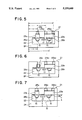
The optical switching connector 21 of FIG. 5 has the pin holding member divided into a pin holding member 23a which holds down the reference pin 15 in the narrow width pin groove 26a and the pin holding member 23b which holds down the reference pin 15 in the wide width pin groove 26b, has the pin holding member 23a on the narrow width pin groove 26a pressed to the reference pin 15 by the screw 25a and has the pin holding member 23b of the wide width pin groove 26b side is eliminated and the switching operation can be performed smoothly.
When 500 switching operations were performed using the optical switching connector of the above construction, the amount of change of the transmission loss was no more than 0.2 dB.
The optical switching connector 21 of FIG. 6 has the reference pin 15 in the narrow width pin groove 26a pressed by the screw 25a. That is, in this embodiment, the screw 25a serves also as a pin holding member. The rest of the construction is the same as in FIG. 5.
The optical switching connector 21 of FIG. 7 has the thickness T of the bottom portion of the frame body 24 made the same as the thickness U of the ferrule plate 22 to prevent the ferrule plate 22 from bending as shown by the dotted line B.
In this type of optical switching connector, the thickness U of the ferrule plate 22 must be 4 mm. As opposed to this, the thickness T of the bottom portion of the frame body 24 was changed to investigate the increase of the loss L (dB) of the optical switching connector. The results are shown in Table 1.
              TABLE 1                                                     
______________________________________                                    
Thickness T of bottom                                                     
of frame body    Increment of loss L                                      
(mm)             (dB)                                                     
______________________________________                                    
1.5              5.10                                                     
2.0              2.87                                                     
3.0              0.72                                                     
4.0              0                                                        
______________________________________                                    
If by this the thickness T of the bottom portion of the frame body is made the same or greater than the thickness U of the ferrule plate, it is understood that the increase of loss L caused by the bending of the ferrule plate can be eliminated. When the thickness T of the bottom portion of the frame body is 4.0 mm, if the screws 25a, 25b1, and 25b2 are used to fix the ferrule plate 22 by an axial force of up to 1.5 kg, the amount of bending of the bottom portion of the frame body 24 caused by the axial force becomes no more than 1 μm and therefore the bending of the ferrule plate 22 can be almost completely eliminated and the increase in the transmission loss caused by the bending can also be almost completely eliminated.
Note that in the embodiment, use is made of stainless steel for the frame body, but if use is made of a superhard alloy or ceramic for the frame body, the thickness of the bottom portion of the frame body may be made thinner than in the above case.
As explained above, according to the present invention, the bending of the pin holding member corresponding to the pin groove where the reference pin can move horizontally is eliminated, and thus the switching can be performed smoothly. Further, the reference pins can be fixed securely without regard to dimensional error, and therefore the positioning by the reference pins becomes more accurate and it is possible to form an optical switching connector with very little connection loss. Further, if the thickness of the bottom portion of the frame body is made at least the thickness of the ferrule plate, the bending of the ferrule plate almost completely disappears and in this regard too it is possible to reduce the connection loss.

Claims (2)

We claim:
1. An optical switching connector comprising:
a ferrule plate fixing an end of an optical fiber to a predetermined position, having pin grooves formed in parallel at its both ends, and having at least one of its pin grooves formed to a width enabling horizontal movement of a reference pin;
pin holding members positioning the reference pin in said pin grooves; and
a frame body housing said ferrule plate and pin holding members.
wherein said pin holding members are provided individually for each pin groove, and
wherein provision is made at the both sides of the pin grooves of a means for pressing the pin holding members corresponding to the pin grooves where said reference pins can move horizontally to the ferrule plate.
2. An optical switching connector as set forth in claim 1, wherein the thickness of the bottom portion of the frame body is at least the thickness of the ferrule plate.
US07/706,694 1990-05-30 1991-05-29 Optical switching connector Expired - Fee Related US5159649A (en)

Applications Claiming Priority (2)

Application Number Priority Date Filing Date Title
JP2138346A JP2967833B2 (en) 1990-05-30 1990-05-30 Optical switching connector
JP2-138346 1990-05-30

Publications (1)

Publication Number Publication Date
US5159649A true US5159649A (en) 1992-10-27

Family

ID=15219777

Family Applications (1)

Application Number Title Priority Date Filing Date
US07/706,694 Expired - Fee Related US5159649A (en) 1990-05-30 1991-05-29 Optical switching connector

Country Status (7)

Country Link
US (1) US5159649A (en)
EP (1) EP0459776A3 (en)
JP (1) JP2967833B2 (en)
KR (1) KR910020466A (en)
AU (1) AU641017B2 (en)
CA (1) CA2043446A1 (en)
SG (1) SG52162A1 (en)

Cited By (4)

* Cited by examiner, † Cited by third party
Publication number Priority date Publication date Assignee Title
US5623564A (en) * 1995-06-07 1997-04-22 Lucent Technologies Inc. Self-aligned mechanical optical switch
US5828800A (en) * 1997-06-23 1998-10-27 Lucent Technologies Inc. Self-aligned mechanical M×N optical switch
US5920665A (en) * 1997-06-06 1999-07-06 Lucent Technologies Inc. Mechanical optical fiber switch having enhanced alignment
CN100359351C (en) * 2005-10-28 2008-01-02 张政雄 Communication switching device

Families Citing this family (7)

* Cited by examiner, † Cited by third party
Publication number Priority date Publication date Assignee Title
DE4109195A1 (en) * 1991-03-18 1992-09-24 Siemens Ag OPTICAL SWITCH
US5185825A (en) * 1991-10-03 1993-02-09 The Furukawa Electric Co., Ltd. Optical switching connector
DE4204567C2 (en) * 1992-02-13 1999-10-07 Siemens Ag Optical switch
DE19635023A1 (en) * 1995-08-30 1997-03-06 Spinner Gmbh Elektrotech Optical waveguide switch
US6305850B1 (en) * 1998-12-31 2001-10-23 Corning Cable Systems Llc Multifiber alignment adapter and associated fiber optic connector subassembly
US6736546B2 (en) * 2001-08-31 2004-05-18 Teradyne, Inc. Optical connector ferrule designed to minimize manufacturing imperfections and mating misalignments by incorporating exact constraint principles
US7240425B2 (en) 2003-04-24 2007-07-10 Amphenol Corporation Method of making an electrical connection to a conductor on an inner layer of a multi-layer printed circuit board

Citations (2)

* Cited by examiner, † Cited by third party
Publication number Priority date Publication date Assignee Title
US4607910A (en) * 1983-10-14 1986-08-26 Telefonaktiebolaget Lm Ericsson Optical fiber switch having a movable fiber secured to a slide which is indirectly moved by a magnetic armature
US4778243A (en) * 1986-12-08 1988-10-18 Siemens Aktiengesellschaft Connector element for a light waveguide

Family Cites Families (2)

* Cited by examiner, † Cited by third party
Publication number Priority date Publication date Assignee Title
JPH0740094B2 (en) * 1986-09-29 1995-05-01 日本電信電話株式会社 Optical fiber switch
DE3633340A1 (en) * 1986-10-01 1988-04-07 Standard Elektrik Lorenz Ag COUPLING DEVICE FOR LIGHTWAVE GUIDE

Patent Citations (2)

* Cited by examiner, † Cited by third party
Publication number Priority date Publication date Assignee Title
US4607910A (en) * 1983-10-14 1986-08-26 Telefonaktiebolaget Lm Ericsson Optical fiber switch having a movable fiber secured to a slide which is indirectly moved by a magnetic armature
US4778243A (en) * 1986-12-08 1988-10-18 Siemens Aktiengesellschaft Connector element for a light waveguide

Cited By (4)

* Cited by examiner, † Cited by third party
Publication number Priority date Publication date Assignee Title
US5623564A (en) * 1995-06-07 1997-04-22 Lucent Technologies Inc. Self-aligned mechanical optical switch
US5920665A (en) * 1997-06-06 1999-07-06 Lucent Technologies Inc. Mechanical optical fiber switch having enhanced alignment
US5828800A (en) * 1997-06-23 1998-10-27 Lucent Technologies Inc. Self-aligned mechanical M×N optical switch
CN100359351C (en) * 2005-10-28 2008-01-02 张政雄 Communication switching device

Also Published As

Publication number Publication date
KR910020466A (en) 1991-12-20
AU641017B2 (en) 1993-09-09
CA2043446A1 (en) 1991-12-01
JPH0432810A (en) 1992-02-04
EP0459776A3 (en) 1992-05-20
JP2967833B2 (en) 1999-10-25
EP0459776A2 (en) 1991-12-04
SG52162A1 (en) 1998-09-28
AU7802991A (en) 1991-12-05

Similar Documents

Publication Publication Date Title
EP0482673B1 (en) Optical connector
US5159649A (en) Optical switching connector
US6062740A (en) Optical connector and method of making the same
CA1311381C (en) Connector employing mode field modification
JP5117640B2 (en) Optical module
US5727102A (en) Multifiber optical connector for optical ribbon cable
US5971624A (en) Multi-fiber splice mechanism and associated splicing connector
JPH1172659A (en) Optical multiple connector
JP2007065490A (en) Connection terminal of optical fiber and its connection method
US5000530A (en) Optical multiplexing/demultiplexing device with multiple ports
JPH11133269A (en) Optical connector and its production
JP3256925B2 (en) Optical waveguide device
US20230016658A1 (en) Optical Connector Assembly
US20040101230A1 (en) Optical arrangement with a low-radius fiber bend
JP3205833B2 (en) Optical connector plug
US6328481B1 (en) Arrayed optical fiber connector
JP3088829B2 (en) Connector connection structure for waveguide device
JP2752773B2 (en) Light switch
JP2801369B2 (en) Board type optical connector
JP2843338B2 (en) Optical waveguide / optical fiber connector
JP2519233B2 (en) Multi-fiber batch switch for optical fiber
JPH03196004A (en) Waveguide type optical device
JP2002156560A (en) Optical connector and fitting pin
JPH0763952A (en) Optical connector ferrule
Alamed et al. The Performance Of The AT&T Single-Mode ST® Connector And Its Latest Enhanced Features

Legal Events

Date Code Title Description
AS Assignment

Owner name: FURUKAWA ELECTRIC CO., LTD., THE, JAPAN

Free format text: ASSIGNMENT OF ASSIGNORS INTEREST.;ASSIGNORS:UEMURA, YASUO;OOTA, TOSHIHIKO;SHIGEMATSU, TAKASHI;AND OTHERS;REEL/FRAME:005798/0817

Effective date: 19910723

FEPP Fee payment procedure

Free format text: PAYOR NUMBER ASSIGNED (ORIGINAL EVENT CODE: ASPN); ENTITY STATUS OF PATENT OWNER: LARGE ENTITY

FEPP Fee payment procedure

Free format text: PAYOR NUMBER ASSIGNED (ORIGINAL EVENT CODE: ASPN); ENTITY STATUS OF PATENT OWNER: LARGE ENTITY

Free format text: PAYER NUMBER DE-ASSIGNED (ORIGINAL EVENT CODE: RMPN); ENTITY STATUS OF PATENT OWNER: LARGE ENTITY

FPAY Fee payment

Year of fee payment: 4

FPAY Fee payment

Year of fee payment: 8

REMI Maintenance fee reminder mailed
LAPS Lapse for failure to pay maintenance fees
STCH Information on status: patent discontinuation

Free format text: PATENT EXPIRED DUE TO NONPAYMENT OF MAINTENANCE FEES UNDER 37 CFR 1.362

FP Lapsed due to failure to pay maintenance fee

Effective date: 20041027