US5145292A - Air conveying system - Google Patents
Air conveying system Download PDFInfo
- Publication number
- US5145292A US5145292A US07/663,558 US66355891A US5145292A US 5145292 A US5145292 A US 5145292A US 66355891 A US66355891 A US 66355891A US 5145292 A US5145292 A US 5145292A
- Authority
- US
- United States
- Prior art keywords
- air
- conveyor assembly
- support plate
- point
- object discharge
- Prior art date
- Legal status (The legal status is an assumption and is not a legal conclusion. Google has not performed a legal analysis and makes no representation as to the accuracy of the status listed.)
- Expired - Lifetime
Links
Images
Classifications
-
- B—PERFORMING OPERATIONS; TRANSPORTING
- B30—PRESSES
- B30B—PRESSES IN GENERAL
- B30B15/00—Details of, or accessories for, presses; Auxiliary measures in connection with pressing
- B30B15/32—Discharging presses
Definitions
- This invention relates in general to means for conveying objects from an object discharge point to a transfer point and relates in particular to a system for conveying small objects by directing a flow of air against the side of the object and moving it along a conveying surface.
- Another method of transfer in a through the die operation is to deposit the cups onto a moving, endless belt-type conveyor or into pockets in such a conveyor which then moves them away from their point of deposit.
- belt-type conveyors of this general type may be seen in Kaminski et al. U.S. Pat. No. 3,231,065; Maschke U.S. Pat. No. 3,812,953; Kaminski U.S. Pat. No. 4,289,231; and Kaminski U.S. Pat. No. 4,588,066.
- the difficulty again is, however, that, along with the constant down-gauging of the material, increase in speed also becomes more and more desirable.
- Lindstrom et al. U.S. Pat. No. 4,710,068 provides such a means whereby a conveying surface is provided with a plurality of air jets in fluid flow relation with a plenum and an air accelerator hood is provided adjacent the discharge point of the articles onto the conveying surface.
- a plenum is provided adjacent the transfer point, and the air is forced into the plenum, which is disposed beneath the conveying surface and at the conveyor discharge end, and then through the air acceleration hood and against the article which is then pushed along toward the conveyor discharge end or transfer point.
- the air jets in the base of the conveyor are utilized to reduce friction and assist in moving the objects along the conveyor surface.
- such a conveying system can be produced without the previously known plenum and comprising a support plate disposed beneath the object discharge point for receipt of the objects to be conveyed and one or more air-directing nozzles adjacent the point of discharge of the object onto the conveying system, thereby achieving improved conveying properties.
- sensing means can be adjustably mounted on the conveyor system adjacent the point on which the objects are deposited on the conveying surface so that the presence of jams can be readily detected.
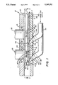
- FIG. 1 is an elevational view of the improved conveying system taken along the line 1--1 of FIG. 2.
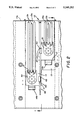
- FIG. 2 is a plan view taken along the line 2--2 of FIG. 1, partially in section and with the cups not shown for clarity of illustration of other elements of the system.
- the conveyor assembly is generally indicated by the numeral 10 and the lower die member is generally indicated by the numeral 20.
- the invention is illustrated and will be described in connection with a forming press which carries upper and lower die members with the upper die member being reciprocal with respect to the lower. In that way, one or more articles, such as cups, can be formed during each press cycle. Further, the arrangement illustrated is a "through the die arrangement" wherein the material is inserted into the press between the upper and lower die members and the formed article is ejected through the lower die member.
- the lower die member 20 has one or more die openings 21 through which the cups C are deposited on the conveyor following forming. Two such openings 21 are illustrated, but it will be readily understood that more or less may be utilized.
- Forming tools 22,22 carried by the upper press ram, reciprocate with respect to the lower die member 20 to form the cups C, passing them through the die openings 21,21 on the conveying surface at what will be referred to herein as the object discharge point.
- the conveyor assembly 10 includes a main body 11 which is intended to be secured to the lower die member 20 in suitable fashion so that it underlies the lower surface of the lower die member and forms an assembly therewith.
- Main body 11 of conveyor assembly 10 has one or more elongate openings 12,12 opening from end 11a and extending inwardly therefrom to terminate at a point generally beneath openings 21,21 in the lower die member 20.
- the number of such openings 12 will correspond to the number of the openings 21 in lower die member 20.
- a substantially imperforate elongate conveyor support member 13 Positioned in each of the elongate openings 12,12 is a substantially imperforate elongate conveyor support member 13. These support members 13,13 extend beneath their respective openings 21 and their top surfaces 13a provide the main conveying surface for the cups C. To that end, a support pad 50 is affixed to each top surface 13a beneath each opening 21 to cushion the fall of cup C and facilitate initial internal movement thereof. Pads 50,50 are preferably fabricated of nylon or a similar material having a low coefficient of friction for this purpose.
- each support member 13 includes one or more elongate, longitudinally extending, raised ribs 13b which, as shown in FIG. 2 of the drawings, extend from a point adjacent the arcuate notches 51 in each pad 50 adjacent the object discharge openings 21 to the end 11a of the body 11.
- a sensor 40 is mounted adjacent each object discharge point and, by virtue of the slot 41 in the sensor mounting plate 42 and screws 43, 43, these sensors are adjustable so as to accommodate different sized objects.
- the purpose of the sensors is to sense whether an object has jammed at the object discharge point.
- the conveyor assembly 10 includes support members 13,13 and the ribs 13b,13b and sensors 40,40. It also includes what may be called air manifolds 14,14. These manifolds each have an elongate body 14a terminating at one end in a curved discharge nozzle 14b and at the other end in a reduced diameter area 14c. This reduced diameter portion receives the hose 30 which leads to the air supply source (not shown).
- the main body 11 has appropriate angularly directed bores 11b,11b which are located so that the discharge nozzles 14b,14b are positioned just to the left of discharge points 21 and just past the inboard ends of conveyor support members 13,13, as can be seen in FIG. 2 of the drawings.
- operation of the device includes operation of the press itself and the tooling which will form the cups C and pass them through the apertures 21,21 of the lower die member 20. They will then be received on pads 50,50 of the conveyor support plate 13, and air will be directed against the walls of the objects through air manifolds 14,14, forcing the objects along the support pads 50,50 and then along the ribs 13b,13b toward the transfer point at end 11a.
- the invention has essentially been described in connection with the forming of cups as part of the overall process of forming two-piece cans. However, it will be readily apparent that in utilization it need not be limited to that particular field.
- the invention has been illustrated in a "two out" situation in which the lower die member 20 contains two forming apertures so that, upon each press cycle, two cups will be formed.
- the nozzles and ribs, etc. are, of course, two in number also.
- the invention need not be so limited.
Landscapes
- Engineering & Computer Science (AREA)
- Mechanical Engineering (AREA)
- Press Drives And Press Lines (AREA)
Abstract
Description
Claims (5)
Priority Applications (1)
| Application Number | Priority Date | Filing Date | Title |
|---|---|---|---|
| US07/663,558 US5145292A (en) | 1991-03-04 | 1991-03-04 | Air conveying system |
Applications Claiming Priority (1)
| Application Number | Priority Date | Filing Date | Title |
|---|---|---|---|
| US07/663,558 US5145292A (en) | 1991-03-04 | 1991-03-04 | Air conveying system |
Publications (1)
| Publication Number | Publication Date |
|---|---|
| US5145292A true US5145292A (en) | 1992-09-08 |
Family
ID=24662347
Family Applications (1)
| Application Number | Title | Priority Date | Filing Date |
|---|---|---|---|
| US07/663,558 Expired - Lifetime US5145292A (en) | 1991-03-04 | 1991-03-04 | Air conveying system |
Country Status (1)
| Country | Link |
|---|---|
| US (1) | US5145292A (en) |
Cited By (4)
| Publication number | Priority date | Publication date | Assignee | Title |
|---|---|---|---|---|
| US5668307A (en) * | 1996-05-07 | 1997-09-16 | Wade; James H. | Apparatus for testing can ends for leaks |
| US20060239808A1 (en) * | 2003-04-03 | 2006-10-26 | Ralph Ludwig | Device for producing a predertermined orientation |
| US20100115889A1 (en) * | 2008-11-11 | 2010-05-13 | Profold, Inc. | Air conveyor and apparatus for applying tab using the air conveyor |
| US20250171252A1 (en) * | 2023-11-28 | 2025-05-29 | Air Con Tech Systems, Inc. | Can blank conveyor assembly and method of use |
Citations (13)
| Publication number | Priority date | Publication date | Assignee | Title |
|---|---|---|---|---|
| US3231065A (en) * | 1963-01-14 | 1966-01-25 | Stolle Corp | Article feeding apparatus |
| GB1277194A (en) * | 1968-05-21 | 1972-06-07 | Peter Lazenby | Improvements relating to the conveying of articles or other loads on carriers |
| US3812953A (en) * | 1970-10-29 | 1974-05-28 | Stolle Corp | Driving or idler drum for article feeding belt |
| SU575298A1 (en) * | 1975-12-02 | 1977-10-05 | Kornienko Valerij | Device for introducing materials in bulk into horizontal pipeline of positive-pressure pneumatic transport plant |
| US4185783A (en) * | 1977-06-14 | 1980-01-29 | Air Industrie | Powder feed device for powder dispensing apparatus |
| US4289231A (en) * | 1979-07-12 | 1981-09-15 | The Stolle Corporation | Article feeding apparatus |
| US4483172A (en) * | 1982-11-26 | 1984-11-20 | Redicon Corporation | System and apparatus for forming containers |
| US4588066A (en) * | 1984-07-26 | 1986-05-13 | The Stolle Corporation | Article feeding apparatus with non-flexing belt |
| US4710068A (en) * | 1986-09-15 | 1987-12-01 | Reynolds Metals Company | Air conveyor |
| US4741196A (en) * | 1987-02-09 | 1988-05-03 | Formatec Tooling Systems, Inc. | Air conveyor and method for removing parts from a high speed forming press |
| US4881397A (en) * | 1987-02-09 | 1989-11-21 | Formatec Tooling Systems, Inc. | Air conveyor for removing parts from a high speed forming press |
| US4903521A (en) * | 1988-09-02 | 1990-02-27 | Redicon Corporation | Method and apparatus for forming, reforming and curling shells in a single press |
| US5017052A (en) * | 1988-08-15 | 1991-05-21 | Bartylla James G | Cup conveyor |
-
1991
- 1991-03-04 US US07/663,558 patent/US5145292A/en not_active Expired - Lifetime
Patent Citations (13)
| Publication number | Priority date | Publication date | Assignee | Title |
|---|---|---|---|---|
| US3231065A (en) * | 1963-01-14 | 1966-01-25 | Stolle Corp | Article feeding apparatus |
| GB1277194A (en) * | 1968-05-21 | 1972-06-07 | Peter Lazenby | Improvements relating to the conveying of articles or other loads on carriers |
| US3812953A (en) * | 1970-10-29 | 1974-05-28 | Stolle Corp | Driving or idler drum for article feeding belt |
| SU575298A1 (en) * | 1975-12-02 | 1977-10-05 | Kornienko Valerij | Device for introducing materials in bulk into horizontal pipeline of positive-pressure pneumatic transport plant |
| US4185783A (en) * | 1977-06-14 | 1980-01-29 | Air Industrie | Powder feed device for powder dispensing apparatus |
| US4289231A (en) * | 1979-07-12 | 1981-09-15 | The Stolle Corporation | Article feeding apparatus |
| US4483172A (en) * | 1982-11-26 | 1984-11-20 | Redicon Corporation | System and apparatus for forming containers |
| US4588066A (en) * | 1984-07-26 | 1986-05-13 | The Stolle Corporation | Article feeding apparatus with non-flexing belt |
| US4710068A (en) * | 1986-09-15 | 1987-12-01 | Reynolds Metals Company | Air conveyor |
| US4741196A (en) * | 1987-02-09 | 1988-05-03 | Formatec Tooling Systems, Inc. | Air conveyor and method for removing parts from a high speed forming press |
| US4881397A (en) * | 1987-02-09 | 1989-11-21 | Formatec Tooling Systems, Inc. | Air conveyor for removing parts from a high speed forming press |
| US5017052A (en) * | 1988-08-15 | 1991-05-21 | Bartylla James G | Cup conveyor |
| US4903521A (en) * | 1988-09-02 | 1990-02-27 | Redicon Corporation | Method and apparatus for forming, reforming and curling shells in a single press |
Cited By (7)
| Publication number | Priority date | Publication date | Assignee | Title |
|---|---|---|---|---|
| US5668307A (en) * | 1996-05-07 | 1997-09-16 | Wade; James H. | Apparatus for testing can ends for leaks |
| US20060239808A1 (en) * | 2003-04-03 | 2006-10-26 | Ralph Ludwig | Device for producing a predertermined orientation |
| US7435039B2 (en) * | 2003-04-03 | 2008-10-14 | Braun Gmbh | Device for producing a predetermined orientation |
| US20100115889A1 (en) * | 2008-11-11 | 2010-05-13 | Profold, Inc. | Air conveyor and apparatus for applying tab using the air conveyor |
| US8424581B2 (en) * | 2008-11-11 | 2013-04-23 | Profold, Inc. | Air conveyor and apparatus for applying tab using the air conveyor |
| US20250171252A1 (en) * | 2023-11-28 | 2025-05-29 | Air Con Tech Systems, Inc. | Can blank conveyor assembly and method of use |
| US12545531B2 (en) * | 2023-11-28 | 2026-02-10 | Air Con Tech Systems, Inc. | Can blank conveyor assembly and method of use |
Similar Documents
| Publication | Publication Date | Title |
|---|---|---|
| US5161919A (en) | Bottle air conveyor | |
| EP0776311B1 (en) | Diverter for bottle air conveyor | |
| US5605217A (en) | Vacuum combiner and vacuum conveyor | |
| US20080251574A1 (en) | Pressware Die Set With Pneumatic Blank Feed | |
| US20050199470A1 (en) | Transport of bulk material items | |
| EP2931634B1 (en) | Can body take-away mechanism for vertical bodymaker | |
| US5775067A (en) | Article selector wedge | |
| US4454743A (en) | Integrated container manufacturing system and method | |
| KR900004418A (en) | Method and apparatus for shaping and reshaping the shell in a single press | |
| US5145292A (en) | Air conveying system | |
| US6510938B1 (en) | Soft touch infeed | |
| US6918588B2 (en) | Device for separating printing products transported in an imbricated formation into a succession of spaced printing products | |
| JP2018075509A (en) | Fruit vegetable sorting apparatus and fruit vegetable sorting method | |
| US6640953B2 (en) | Controlled gravity accumulation conveyor | |
| US4204672A (en) | Device for conveying sheets within a sheet processing machine | |
| US5017052A (en) | Cup conveyor | |
| US5171007A (en) | Sheet feeding device having an adjustable sheet restrainer | |
| US20080267736A1 (en) | System for forming and securing lift-tabs to can ends having an elongated crank shaft | |
| US3618550A (en) | Method and apparatus for controlling the supply in a can end processing system | |
| US4741196A (en) | Air conveyor and method for removing parts from a high speed forming press | |
| US4554814A (en) | Air transfer system and method for a shell press | |
| EP0106435B1 (en) | Air transfer system for a shell press | |
| EP0863100B1 (en) | Apparatus for the manufacture and stacking of layered cellulose products | |
| US3368666A (en) | Conveyor guide rail | |
| CA2259816A1 (en) | Low pressure dynamic accumulation table |
Legal Events
| Date | Code | Title | Description |
|---|---|---|---|
| AS | Assignment |
Owner name: REDICON CORPORATION, 2824 WOODLAWN AVENUE, N.W., C Free format text: ASSIGNMENT OF ASSIGNORS INTEREST.;ASSIGNORS:BULSO, JOSEPH D. JR.;MCCLUNG, JAMES A.;DOTTAVIO, ALEXANDER P.;REEL/FRAME:005640/0333 Effective date: 19910301 |
|
| STCF | Information on status: patent grant |
Free format text: PATENTED CASE |
|
| FEPP | Fee payment procedure |
Free format text: PAYOR NUMBER ASSIGNED (ORIGINAL EVENT CODE: ASPN); ENTITY STATUS OF PATENT OWNER: LARGE ENTITY |
|
| FPAY | Fee payment |
Year of fee payment: 4 |
|
| AS | Assignment |
Owner name: NATIONAL CITY BANK, OHIO Free format text: ASSIGNMENT OF ASSIGNORS INTEREST;ASSIGNOR:REDICON CORPORATION;REEL/FRAME:010164/0829 Effective date: 19990804 |
|
| FPAY | Fee payment |
Year of fee payment: 8 |
|
| FEPP | Fee payment procedure |
Free format text: PAT HOLDER NO LONGER CLAIMS SMALL ENTITY STATUS, ENTITY STATUS SET TO UNDISCOUNTED (ORIGINAL EVENT CODE: STOL); ENTITY STATUS OF PATENT OWNER: LARGE ENTITY |
|
| REFU | Refund |
Free format text: REFUND - PAYMENT OF MAINTENANCE FEE, 12TH YR, SMALL ENTITY (ORIGINAL EVENT CODE: R2553); ENTITY STATUS OF PATENT OWNER: LARGE ENTITY |
|
| AS | Assignment |
Owner name: STOLLE MACHINERY, INC., OHIO Free format text: ASSIGNMENT OF ASSIGNORS INTEREST;ASSIGNOR:NATIONAL CITY BANK;REEL/FRAME:014261/0758 Effective date: 20000208 |
|
| AS | Assignment |
Owner name: STOLLE MACHINERY COMPANY, LLC, COLORADO Free format text: MERGER AND CHANGE OF NAMES;ASSIGNORS:STOLLE MACHINERY, INC.;APE ACQUISITION, LLC;REEL/FRAME:014321/0208 Effective date: 20040109 |
|
| AS | Assignment |
Owner name: GMAC COMMERICAL FINANCE, LLC, NEW YORK Free format text: SECURITY INTEREST;ASSIGNOR:STOLLE MACHINERY COMPANY, LLC;REEL/FRAME:014357/0546 Effective date: 20040109 |
|
| FPAY | Fee payment |
Year of fee payment: 12 |
|
| FEPP | Fee payment procedure |
Free format text: ENTITY STATUS SET TO UNDISCOUNTED (ORIGINAL EVENT CODE: BIG.); ENTITY STATUS OF PATENT OWNER: LARGE ENTITY |
|
| AS | Assignment |
Owner name: GOLDMAN SACHS CREDIT PARTNERS L.P.,NEW YORK Free format text: FIRST LIEN PATENT SECURITY AGREEMENT;ASSIGNOR:STOLLE MACHINERY COMPANY, LLC;REEL/FRAME:018454/0672 Effective date: 20060929 Owner name: GOLDMAN SACHS CREDIT PARTNERS L.P.,NEW YORK Free format text: SECOND LIEN PATENT SECURITY AGREEMENT;ASSIGNOR:STOLLE MACHINERY COMPANY, LLC;REEL/FRAME:018454/0760 Effective date: 20060929 Owner name: STOLLE MACHINERY COMPANY, LLC, COLORADO Free format text: RELEASE BY SECURED PARTY;ASSIGNOR:GMAC COMMERCIAL FINANCE LLC;REEL/FRAME:018454/0709 Effective date: 20060928 Owner name: GOLDMAN SACHS CREDIT PARTNERS L.P., NEW YORK Free format text: SECOND LIEN PATENT SECURITY AGREEMENT;ASSIGNOR:STOLLE MACHINERY COMPANY, LLC;REEL/FRAME:018454/0760 Effective date: 20060929 Owner name: GOLDMAN SACHS CREDIT PARTNERS L.P., NEW YORK Free format text: FIRST LIEN PATENT SECURITY AGREEMENT;ASSIGNOR:STOLLE MACHINERY COMPANY, LLC;REEL/FRAME:018454/0672 Effective date: 20060929 |
|
| AS | Assignment |
Owner name: STOLLE MACHINERY COMPANY, LLC, COLORADO Free format text: RELEASE OF SECURITY INTEREST IN PATENT COLLATERAL - SECOND LIEN RECORDED AT REEL/FRAME 018454/0760;ASSIGNOR:GOLDMAN SACHS CREDIT PARTNERS L.P.;REEL/FRAME:021291/0584 Effective date: 20080725 Owner name: STOLLE MACHINERY COMPANY, LLC, COLORADO Free format text: RELEASE OF SECURITY INTEREST IN PATENT COLLATERAL - FIRST LIEN RECORDED AT REEL/FRAME 018454/0672;ASSIGNOR:GOLDMAN SACHS CREDIT PARTNERS L.P.;REEL/FRAME:021291/0623 Effective date: 20080725 Owner name: GOLDMAN SACHS CREDIT PARTNERS L.P., NEW YORK Free format text: PATENT SECURITY AGREEMENT;ASSIGNOR:STOLLE MACHINERY COMPANY, LLC;REEL/FRAME:021291/0651 Effective date: 20080725 Owner name: GOLDMAN SACHS CREDIT PARTNERS L.P.,NEW YORK Free format text: PATENT SECURITY AGREEMENT;ASSIGNOR:STOLLE MACHINERY COMPANY, LLC;REEL/FRAME:021291/0651 Effective date: 20080725 Owner name: STOLLE MACHINERY COMPANY, LLC,COLORADO Free format text: RELEASE OF SECURITY INTEREST IN PATENT COLLATERAL - SECOND LIEN RECORDED AT REEL/FRAME 018454/0760;ASSIGNOR:GOLDMAN SACHS CREDIT PARTNERS L.P.;REEL/FRAME:021291/0584 Effective date: 20080725 Owner name: STOLLE MACHINERY COMPANY, LLC,COLORADO Free format text: RELEASE OF SECURITY INTEREST IN PATENT COLLATERAL - FIRST LIEN RECORDED AT REEL/FRAME 018454/0672;ASSIGNOR:GOLDMAN SACHS CREDIT PARTNERS L.P.;REEL/FRAME:021291/0623 Effective date: 20080725 |
|
| AS | Assignment |
Owner name: STOLLE MACHINERY COMPANY, LLC, COLORADO Free format text: TERMINATON AND RELEASE OF SECURITY INTEREST IN PATENT COLLATERAL RECORDED AT REEL/FRAME 021291/0651;ASSIGNOR:GOLDMAN SACHS CREDIT PARTNERS L.P.;REEL/FRAME:027172/0522 Effective date: 20111103 |