EP0106435B1 - Air transfer system for a shell press - Google Patents
Air transfer system for a shell press Download PDFInfo
- Publication number
- EP0106435B1 EP0106435B1 EP19830303967 EP83303967A EP0106435B1 EP 0106435 B1 EP0106435 B1 EP 0106435B1 EP 19830303967 EP19830303967 EP 19830303967 EP 83303967 A EP83303967 A EP 83303967A EP 0106435 B1 EP0106435 B1 EP 0106435B1
- Authority
- EP
- European Patent Office
- Prior art keywords
- shell
- station
- blanking
- slide
- die station
- Prior art date
- Legal status (The legal status is an assumption and is not a legal conclusion. Google has not performed a legal analysis and makes no representation as to the accuracy of the status listed.)
- Expired
Links
- 239000012530 fluid Substances 0.000 claims description 14
- 235000013361 beverage Nutrition 0.000 claims description 6
- 238000007493 shaping process Methods 0.000 claims description 4
- 230000001360 synchronised effect Effects 0.000 claims 1
- 239000011324 bead Substances 0.000 description 11
- 238000009434 installation Methods 0.000 description 3
- 239000000463 material Substances 0.000 description 2
- 230000002093 peripheral effect Effects 0.000 description 2
- XUIMIQQOPSSXEZ-UHFFFAOYSA-N Silicon Chemical compound [Si] XUIMIQQOPSSXEZ-UHFFFAOYSA-N 0.000 description 1
- 229910000831 Steel Inorganic materials 0.000 description 1
- ATJFFYVFTNAWJD-UHFFFAOYSA-N Tin Chemical compound [Sn] ATJFFYVFTNAWJD-UHFFFAOYSA-N 0.000 description 1
- XAGFODPZIPBFFR-UHFFFAOYSA-N aluminium Chemical compound [Al] XAGFODPZIPBFFR-UHFFFAOYSA-N 0.000 description 1
- 229910052782 aluminium Inorganic materials 0.000 description 1
- 239000004411 aluminium Substances 0.000 description 1
- 238000013459 approach Methods 0.000 description 1
- 230000000712 assembly Effects 0.000 description 1
- 238000000429 assembly Methods 0.000 description 1
- 235000013305 food Nutrition 0.000 description 1
- 238000004519 manufacturing process Methods 0.000 description 1
- 230000004048 modification Effects 0.000 description 1
- 238000012986 modification Methods 0.000 description 1
- 239000000565 sealant Substances 0.000 description 1
- 229910052710 silicon Inorganic materials 0.000 description 1
- 239000010703 silicon Substances 0.000 description 1
- 239000010959 steel Substances 0.000 description 1
- 235000012431 wafers Nutrition 0.000 description 1
Images


Classifications
-
- B—PERFORMING OPERATIONS; TRANSPORTING
- B21—MECHANICAL METAL-WORKING WITHOUT ESSENTIALLY REMOVING MATERIAL; PUNCHING METAL
- B21D—WORKING OR PROCESSING OF SHEET METAL OR METAL TUBES, RODS OR PROFILES WITHOUT ESSENTIALLY REMOVING MATERIAL; PUNCHING METAL
- B21D51/00—Making hollow objects
- B21D51/16—Making hollow objects characterised by the use of the objects
- B21D51/38—Making inlet or outlet arrangements of cans, tins, baths, bottles, or other vessels; Making can ends; Making closures
- B21D51/44—Making closures, e.g. caps
-
- B—PERFORMING OPERATIONS; TRANSPORTING
- B21—MECHANICAL METAL-WORKING WITHOUT ESSENTIALLY REMOVING MATERIAL; PUNCHING METAL
- B21D—WORKING OR PROCESSING OF SHEET METAL OR METAL TUBES, RODS OR PROFILES WITHOUT ESSENTIALLY REMOVING MATERIAL; PUNCHING METAL
- B21D43/00—Feeding, positioning or storing devices combined with, or arranged in, or specially adapted for use in connection with, apparatus for working or processing sheet metal, metal tubes or metal profiles; Associations therewith of cutting devices
- B21D43/02—Advancing work in relation to the stroke of the die or tool
- B21D43/18—Advancing work in relation to the stroke of the die or tool by means in pneumatic or magnetic engagement with the work
Definitions
- the invention relates to an air transfer system, and more particularly to an air transfer system for a shell press having a blanking and forming die station and a curling die station commonly operated therein.
- Beverage cans, food cans and the like have a can body and separately manufactured ends, which are called shells that are sealed to the can body.
- the shells are manufactured from sheet steel, aluminium, or other acceptable material in a series of pressures, wherein the shell is blanked and formed in one press and then transported to a second press which curls the edges of the blanked and formed shell.
- the uncurled shell has a peripheral edge that is generally perpendicularly disposed to the main body of the shell, and, before the shell is stacked and then sealed to the beverage can it must first be curled at its peripheral edge and then coated with a sealant which forms a resilient gasket against the can body.
- US-A-3537291 describes apparatus for forming such end closures for cans.
- a major problem currently existing in the industry is directly related to the use of separate presses to blank and form the shell and to curl the shell.
- the blanked and formed shells may first have to be stacked one upon the other and then transported to the curling die station to be curled, or the situation may arise wherein it is necessary to store stacked blanked and formed shells due to unforeseen circumstances, for example, an inoperable curler.
- the shapes of the blanked and formed shells permit them to be conveniently stacked since one shell tightly nests within another.
- the blanked and formed shells tightly nest one upon the other, it is virtually impossible to mechanically cut an individual shell from a tightly nested stack of shells. This requires the shells to be stored in an unstacked state, which requires considerable space and is time consuming, costly and inefficient.
- the blanking and forming die station and curling die station are in close proximity with one another so that the blanked and formed shells may be transported to the curling die station, for example, by use of a conveyor assembly.
- the shells are generally blanked and formed from the strip stock in groups of twelve, fourteen, or sixteen.
- a group of sixteen may be blanked and formed from the strip stock in two rows of eight, which rows are staggered relative to each other to minimize the strip stock skeleton remaining after the blanking and forming operation. Since it is not practical to stack the blanked and formed shells, it is necessary to keep them separated from each other between the blanking and forming die station and curling die station.
- a typical prior art embodiment of the above shell press installation comprises a double acting press than blanks and forms the shells, a ring curler fur curling the blanked and formed shells, and a conveyor assembly extending therebetween.
- the blanked and formed shells may be delivered to the conveyor assembly in one of two common ways.
- the blanking and forming shell press may be designed to tilt towards the conveyor assembly so that the blanked and formed shells slide from the press onto the conveyor for conveyance to the ring curler, or a mechanical kicker-type device may be used with a stationary blanking and forming shell press to eject the blanked and formed shells onto the conveyor.
- the ring curler generally comprises two rotating rollers between which the shells pass to be curled.
- Another typical prior art embodiment which may be a modification of the above described embodiment, uses a die curler in place of the ring curler.
- the blanked and formed shell is curled at a die station, which is commonly housed in a press separate from the blanking and forming shell press and operated independently thereof.
- the distance between the blanking and forming shell press and the die curler may be such that a conveyor assembly may be used to transport blanked and formed shells to the die curler.
- Stacking for transporting to the die curler is not practical due to the tight nesting of a stack of blanked and formed shells.
- pneumatic systems which generally comprise a large plenum and duct assembly.
- parts such as bottles, cans, records, silicon wafers and the like are transported along a guide track overlying the ducts.
- the ducts have a plurality of openings disposed therein and the plenum provides a source of low pressure air which flows through the ducts and out the openings to convey the part from one area to another.
- This type of system poses numerous disadvantages when adapted to a shell press wherein a plurality of shells are formed simultaneously.
- shells are blanked and formed in groups of twelve, fourteen, or sixteen and in rows which are staggered relative to each other such that shells formed in one row overlap shells of adjacent rows. Therefore, it is desirable to transport alternate rows along different paths or tracks, which may be disposed relative to each other in a vertically adjacent manner. In such an arrangement, it is not practical or efficient to utilize the pneumatic systems of the prior art because of the large size of the ducts that provide air flow to the tracks. Such prior art systems would be difficult to adapt to a blanking and forming die station and a curling die station operated in the same shell press, and would also require an undue amount of material and space.
- the present invention provides a shell press for making shells for beverage cans and the like, comprising:
- the curled shells may be easily stacked and, more importantly, easily cut mechanically from a stack.
- a further advantage of utilizing a die curler in the same shell press with a blanking and forming die station is the uniform shape of curled edges produced by the die in contrast to the curled edges produced by a ring curler.
- the pneumatic transfer system provided is compact and easily interfaced between the blanking and forming die station and curling die station in the same shell press.
- the pneumatic transfer system may comprise two guide tracks extending between the die stations in a double-deck arrangement. Disposed in the upwardly facing. surface of each of the guide tracks is a hollow tube having a diameter much smaller than the width of the guide track or the diameter of the shell being conveyed.
- Each hollow tube has a plurality of uniquely shaped openings which provide air flow velocity components in the direction of the curling station, and each is connected to an air source which provides a flow of high pressure air. Because the pneumatic system of the present invention utilizes a very small diameter hollow tube in place of the large plenum and duct assembly of the prior art pneumatic systems, the pneumatic system of the present invention is easily installed between a doubledeck guide track arrangement, thereby reducing space requirements and costs.
- the present invention minimizes the number of dented shells caused by mechanical kicker-type devices in ejecting the shells from a particular die station.
- an ejecting or escapement mechanism which directs a pulse of air against a curled shell to eject the shell from the curling die station onto a guide track leading therefrom.
- the invention also provides a shell press for making shells for beverage cans and the like, comprising:
- shell press 12 comprising blanking and forming die station 14, air conveyor assembly 16, and curling die station 18. Not shown is a strip stock feeder which feeds strip stock 20 to shell press 12 and a scrap cutter for collecting the skeleton of strip stock 20.
- blanking and forming die station 14 comprises stationary bolster 22 secured to a press bed (not shown) and cutting die retainer assembly 24 secured on the upper surface thereof.
- Lower forming die 26 the cross section of which is circular in a plain parallel to tin line 28, is securely mounted within cutting die retainer assembly 24.
- Bolster 22 and cutting die retainer assembly 24 are rigidly connected to the shell press frame (not shown).
- Lower forming die 26 also includes an annular bead portion 30, which forms a correspondingly shaped bead portion 32 in shell 66.
- Double action slide assembly 35 comprises blanking slide 36 slidably received on shell press posts (not shown) and forming slide 38 slidably guided by blanking slide 36.
- Slides 36, 38 are driven by connecting rods and a crankshaft operated by an electric motor (not shown) similar to that shown in US patent 3,902,347.
- Housing assembly 40 Securely mounted to blanking slide 36 is housing assembly 40, which is slidably disposed with respect to spindle 42 and which retains punch 44 for slidable movement relative thereto.
- Air pressure from air passage 46 yieldably and continuously urges punch 44 downwardly towards annular cutting die 48 in cutting die retainer assembly 24.
- Upper forming die 50 is rigidly connected to spindle 42 by retaining rod 52, which is threadedly secured at its lower end to forming die 50 and held against spindle 42 at its upper end by nut 54.
- Spindle 42 is secured to top plate 56, which is connected to forming slide 38.
- a dowel 58 prevents rotation between forming die 38 and spindle 42, and forming die 50 has an annular bead portion 60 about its periphery.
- ejector mechanism 62 has ejector bar 64 in a ready position to eject blanked and formed shell 66 from blanking and forming die station 14.
- ejector bar 64 is positively moved by ejector mechanism 62 to a position therein it contacts shell 66 and thereafter is positively, rapidly accelerated to eject shell 66 from die station 14 upwardly along incline 68 to air conveyor assembly 16.
- air conveyor assembly 16 comprises elongated guide track 70, hollowtube 72 extending the length of guide track 70, shaped openings 74 disposed in hollow tube 72, and a source of high pressure air flow (not shown) connected to hollow tube 72 by a suitable connector 76.
- a suitable connector 76 a source of high pressure air flow (not shown) connected to hollow tube 72 by a suitable connector 76.
- a support plate 78 extends between blanking and forming die station 14 and curling die station 18 and has incline 68 secured to its left hand end portion by screws 80 received through incline holes 82 and threaded hole 84 in support plate 78.
- Incline 68 has a narrow neck portion 86 (Fig. 3) for ease of installation only, and upwardly facing surface 88 (Fig. 4) of incline 68 is formed by a tapering end section of guide track 70, which is secured to support plate 78 by screws 90 received through guide track holes 92 and threaded holes (not shown) in support plate 78.
- guide track 70 has a lower surface 94 with a groove 96 centrally disposed longitudinally therein. Secured within the length of groove 96 is hollow tube 72 having one end 100 closed and the other end 102 (Fig. 1 B) connected to connector 76 to supply high pressure air flow through the length of hollow tube 72.
- the very small diameter of hollow tube 72 in relation to the width of lower surface 94 and the diameter of a shell 66 is important. This allows hollow tube 72 to be easily installed in narrow spaces, for example, between guide tracks positioned one upon the other to provide fluid conveyance of shells from one area to a second area within shell press 12.
- Hollow tube 72 has a plurality of shaped openings 74 uniquely stamped therein. Each stamped portion 104 (Figs.
- hollow tube 72 has a concave surface 106 and a convex surface 108, which faces generally inwardly of hollow tube 72. Consequently, when a supply of high pressure air is provided in hollow tube 72, a flow of high pressure air is discharged through each of the shaped openings 74 providing generally perpendicular and generally parallel velocity components relative to lower surface 94, whereby a shell 66 may be lifted upwardly and moved along lower surface 94 in the direction of the parallel velocity components.
- opposite side walls 110 (Fig. 5) upstand from lower surface 94 and each side wall 110 has an overhanging extension 112 inwardly disposed over lower surface 94.
- Side walls 110 are spaced apart a distance slightly greater than the diameter of a shell 66, and remote ends 114 of overhanging extensions 112 are spaced apart a distance slightly less than the diameter of shell 66.
- Side walls 110 and overhanging extensions 112 permit a shell 66 to be fluid conveyed over lower surface 94 in a manner depicted in Fig. 5. Note that shell 66 is lifted above lower surface 94 by the perpendicular velocity components exiting shaped openings 74 and moved along lower surface 94 by the parallel velocity components exiting shaped openings 74.
- curling die station 18 comprises curling die retainer assembly 116, lower curling die 118, liftout device 120, upper curling die 122, and sleeve 124.
- Curling die retainer assembly 116 is securely mounted to stationary bolster 22 and has lower curling die 118 and liftout device 120 included therein.
- Lift out device 120 comprises annular lift out element 126 slidably received within curling die retainer assembly 116 and about lower curling die 118. Lift out element 126 is also receivable within circular groove 130 in bolster 22, however, lift out element 126 is biased upwardly by annular spring 128 disposed within groove 130.
- Lift out arm 132 is slidably received within opening 136, which has a narrow upper portion 138 and a wider lower portion 140.
- Lift out arm 132 has cylindrical seat 134 secured to its upper end, and a small piston 142 secured to its lower end in lower portion 140 of opening 136. Lift out arm 132 is biased upwardly by spring 144, which is disposed below piston 142 and in opening lower portion 140 and cylindrical bore 146 in bolster 22.
- piston' 148 Slidably disposed in upper curling die 122 is piston' 148 which has a narrow midportion 150 slidably received within opening 152, upper portion 154 slidably received within opening 156, and lower portion 158 slidably received within opening 160.
- Two 0-ring seals 162,164 are disposed in respective grooves 166, 168 in upper curling die 122 and piston upper portion 154, respectively.
- a source (not shown) of air provides air under pressure to space 170 defined by opening 156 in upper curling die 122 and slide opening 172 in which upper curling die 122 is slidably received.
- Sleeve 124 has opening 174 disposed in its side and vertically aligned with guide track lower surface 94, and an angled opening 176 disposed in its side just slightly below opening 174. Opening 174 has vertical and lateral dimensions sufficient to allow a blanked and formed shell 66 to pass therethrough into curling die station 18.
- Conduit 178 is disposed in support 180 of curling die retainer assembly 116 and has a source (not shown) of air flow connected to it opposite end.
- a limit switch (not shown) in curling die station 18 causes the source of air connected to the opposite end of conduit 178 to emit a pulse of air flow through conduit 178 when angled opening 176 becomes aligned therewith (Fig. 8).
- opening 182 Disposed in sleeve 124 on its side opposite opening 174 and just slightly below opening 174 is opening 182 which has vertical and lateral dimensions sufficient for the ejection of a curled shell 188 therethrough.
- Guide track 70 is connected to support 180, which has a hole 184 disposed therein to allow a conveyed blanked and formed shell 66 to pass therethrough into curling die station 18.
- Support 180 has a second hole 186 disposed therein to allow an ejected curled shell 188 to pass therethrough for further conveyance by air conveyor assembly 16.
- Fig. 9 illustrates a blanked and formed shell 66 being received within curling die station 18 and it should be noted that the upper surface 190 of seat 134 is substantially coplanar with guide track lower surface 94 and support hole 184 so that shell 66 may be smoothly conveyed within curling die station 18.
- Fig. 8 illustrates a curled shell 188 being ejected from curling die station 18, and it should be noted that upper surface 190 is substantially co-planar with support hole 186 and lower surface 94 of air conveyor assembly 16.
- blanking and forming die station 14 Upon receiving a portion of strip stock 20, blanking and forming die station 14 blanks and formed a shell 66 and ejector mechanism 62 ejects shell 66 onto guide track lower surface 94 of air conveyor assembly 16. Blanked and formed shell 66 is then conveyed from blanking and forming die station 14 to curling die station 18 by the air jets having perpendicular and parallel velocity components directed through shaped openings 74 of hollow tube 72. Fig.
- FIG. 5 illustrates the position of shell 66 in air conveyor assembly 16 during transport and it may be seen that shell 66 has been lifted by the perpendicular velocity components so that shell bead portion 32 is in contact with overhanging extension 112 to prevent shell 66 from being thrown from lower surface 94, and the parallel velocity components convey shell 66 over lower surface 94 to curling die station 18.
- Fig. 8 illustrates curling die station 18 when the crankshaft (not shown) of shell press 12 at at about 0) of crankshaft rotation. Consequently, blanked and formed shell 66 is shown in its position relative to curling die station 18 at about 01 ⁇ 4 crankshaft rotation, and the previous shell is shown as curled shell 188.
- crankshaft rotation Beginning at approximately 01 ⁇ 4 crankshaft rotation, blanked and formed shell 66 is positioned as illustrated in Fig. 8 in abutment with sleeve 124.
- crankshaft rotation As the crankshaft,continues to rotate, blanking slide 36 is moved downwardly and at approximately 67) crankshaft rotation (Fig. 9) sleeve 124 has moved downwardly to align sleeve opening 174 with support hole 184 to permit shell 66 to be fluidly conveyed through hole 184, opening 174, and into curling die station 18 so that shell 66 is centrally positioned on upper surface 190 of seat 134.
- space 170 has a supply of air therein at a predetermined pressure to bias piston 148 downwardly as depicted in Fig. 8.
- Fig. 10 illustrates curling die station 18 at approximately 1804 crankshaft rotation.
- piston lower portion 158 contacts the upper surface of shell 66 to firmly hold it in place during the curling operation.
- lower curling die 118 is forced downwardly against the spring forces of springs 128, 144.
- upper curling die 122 is forced downwardly by blanking slide 36 under a force that is greater than the force applied against piston 148 by the air in space 170.
- the greater force supplied by blanking slide 36 to upper curling die 122 causes it to curl shell bead portion 32 against inner curling surface 192 of sleeve 124.
- lift out arm 132 has fully compressed spring 144 so that further downward movement by seat 134 is prevented.
- Annular lift out element 126 then moves downwardly a small distance against spring 128 to allow die annular bead portion 196 to fully seat with die annular bead portion 194 to curl shell bead portion 32 against inner curling surface 192.
- blanking slide 36 continues to move upwardly to draw piston lower portion 158 away from the upper surface of curled shell 188 as depicted in Fig. 11, so that curled shell 188 now rests on lift out element 126 and upper surface 190 of seat 134 as depicted in Fig. 11.
- curled shell 188 is being conveyed from curling die station 18 onto lower surface 94 of air conveyor assembly 16.
- sleeve 124 moves upwardly so that sleeve opening 182 becomes aligned with curled shell 188 and sleeve opening 176 becomes aligned with conduit 178.
- a limit switch (not shown) in curling die station 18 is tripped to cause the source of air connected to the opposite end of conduit 178 to emit a pulse of air flow through conduit 178 and sleeve opening 176 against curled shell 188 to eject it through sleeve opening 182 and support hole 186 onto lower surface 94 of air conveyor assembly 16.
- curled shell 188 is fully ejected fluidly from curling die station 18 and a second blanked and formed shell 66 is fluidly conveyed by air conveyor assembly 16 against sleeve 124 to be curled by curling die station 18.
Landscapes
- Engineering & Computer Science (AREA)
- Mechanical Engineering (AREA)
- Press Drives And Press Lines (AREA)
Description
- The invention relates to an air transfer system, and more particularly to an air transfer system for a shell press having a blanking and forming die station and a curling die station commonly operated therein.
- Beverage cans, food cans and the like have a can body and separately manufactured ends, which are called shells that are sealed to the can body. Generally, the shells are manufactured from sheet steel, aluminium, or other acceptable material in a series of pressures, wherein the shell is blanked and formed in one press and then transported to a second press which curls the edges of the blanked and formed shell. The uncurled shell has a peripheral edge that is generally perpendicularly disposed to the main body of the shell, and, before the shell is stacked and then sealed to the beverage can it must first be curled at its peripheral edge and then coated with a sealant which forms a resilient gasket against the can body. By way of example US-A-3537291 describes apparatus for forming such end closures for cans.
- A major problem currently existing in the industry is directly related to the use of separate presses to blank and form the shell and to curl the shell. Depending upon the layout of the manufacturing plant, the blanked and formed shells may first have to be stacked one upon the other and then transported to the curling die station to be curled, or the situation may arise wherein it is necessary to store stacked blanked and formed shells due to unforeseen circumstances, for example, an inoperable curler. In any event, the shapes of the blanked and formed shells permit them to be conveniently stacked since one shell tightly nests within another. However, because the blanked and formed shells tightly nest one upon the other, it is virtually impossible to mechanically cut an individual shell from a tightly nested stack of shells. This requires the shells to be stored in an unstacked state, which requires considerable space and is time consuming, costly and inefficient.
- In some shell press installations, the blanking and forming die station and curling die station are in close proximity with one another so that the blanked and formed shells may be transported to the curling die station, for example, by use of a conveyor assembly. The shells are generally blanked and formed from the strip stock in groups of twelve, fourteen, or sixteen. For example, a group of sixteen may be blanked and formed from the strip stock in two rows of eight, which rows are staggered relative to each other to minimize the strip stock skeleton remaining after the blanking and forming operation. Since it is not practical to stack the blanked and formed shells, it is necessary to keep them separated from each other between the blanking and forming die station and curling die station.
- A typical prior art embodiment of the above shell press installation comprises a double acting press than blanks and forms the shells, a ring curler fur curling the blanked and formed shells, and a conveyor assembly extending therebetween. The blanked and formed shells may be delivered to the conveyor assembly in one of two common ways. The blanking and forming shell press may be designed to tilt towards the conveyor assembly so that the blanked and formed shells slide from the press onto the conveyor for conveyance to the ring curler, or a mechanical kicker-type device may be used with a stationary blanking and forming shell press to eject the blanked and formed shells onto the conveyor. In this particular embodiment, the ring curler generally comprises two rotating rollers between which the shells pass to be curled.
- Although the above embodiment permits the blanking and forming operation and the curling operation to be performed in close proximity to each other, certain problems and disadvantages exist such as the requirement for additional space for the conveyor assembly, frequent denting of shells by the kicker device in ejecting the shells onto the conveyor assembly, and the tendency of the ring curler to produce shells having nonuniform curled edges.
- Another typical prior art embodiment, which may be a modification of the above described embodiment, uses a die curler in place of the ring curler. Here the blanked and formed shell is curled at a die station, which is commonly housed in a press separate from the blanking and forming shell press and operated independently thereof. The distance between the blanking and forming shell press and the die curler may be such that a conveyor assembly may be used to transport blanked and formed shells to the die curler. Stacking for transporting to the die curler is not practical due to the tight nesting of a stack of blanked and formed shells.
- Concerning the conveyance of parts between different shaping operations, means other than conveyor belt assemblies have been utilized, for example, pneumatic systems which generally comprise a large plenum and duct assembly. In these systems, parts such as bottles, cans, records, silicon wafers and the like are transported along a guide track overlying the ducts. The ducts have a plurality of openings disposed therein and the plenum provides a source of low pressure air which flows through the ducts and out the openings to convey the part from one area to another. This type of system poses numerous disadvantages when adapted to a shell press wherein a plurality of shells are formed simultaneously.
- Recalling from above, shells are blanked and formed in groups of twelve, fourteen, or sixteen and in rows which are staggered relative to each other such that shells formed in one row overlap shells of adjacent rows. Therefore, it is desirable to transport alternate rows along different paths or tracks, which may be disposed relative to each other in a vertically adjacent manner. In such an arrangement, it is not practical or efficient to utilize the pneumatic systems of the prior art because of the large size of the ducts that provide air flow to the tracks. Such prior art systems would be difficult to adapt to a blanking and forming die station and a curling die station operated in the same shell press, and would also require an undue amount of material and space.
- Examples of such pneumatic systems may be found in U.S. Patents 3,874,740; 3,975,057; 3,953,076; 3,941,070; 3,293,414; and 3,645,591.
- The present invention provides a shell press for making shells for beverage cans and the like, comprising:
- a slide assembly having a first slide member and a second slide member guided to reciprocate relative to each other, the slide assembly including a blanking and forming die station both of which are operated by said slide assembly;
- a pair of first tooling means mounted in said blanking and forming station for blanking and forming a shell, one of said first tooling means being connected to the first slide member and the other of said first tooling means being connected to the second slide member;
- means for ejecting a blanked and formed shell from the blanking and forming station;
- a pair of second tooling means mounted in said curling die station for curling a blanked and formed shell, said second tooling means being connected to and driven by one of said first and second slide members; and
- fluid conveyor means extending between said die stations for conveying the ejected shell from the blanking and forming station to the curling station, said fluid conveyor means including a pair of opposed side walls defining a track and a hollow tube member having a plurality of openings therein, wherein said tube member is connected to a source of air located remotely from said track, said tube member being located in a bottom portion of said track and being contiguous with and extending substantially the distance between said die stations, said tube member being of relatively small diameter in relation to the transverse distance between said opposed side walls and said openings being shaped to provide air flow velocity components directed both upwardly and toward said curling die station when a flow of air is supplied therethrough.
- Since the shells are formed, blanked and curled in the same shell press, the curled shells may be easily stacked and, more importantly, easily cut mechanically from a stack. A further advantage of utilizing a die curler in the same shell press with a blanking and forming die station is the uniform shape of curled edges produced by the die in contrast to the curled edges produced by a ring curler.
- The pneumatic transfer system provided is compact and easily interfaced between the blanking and forming die station and curling die station in the same shell press. The pneumatic transfer system may comprise two guide tracks extending between the die stations in a double-deck arrangement. Disposed in the upwardly facing. surface of each of the guide tracks is a hollow tube having a diameter much smaller than the width of the guide track or the diameter of the shell being conveyed.
- Each hollow tube has a plurality of uniquely shaped openings which provide air flow velocity components in the direction of the curling station, and each is connected to an air source which provides a flow of high pressure air. Because the pneumatic system of the present invention utilizes a very small diameter hollow tube in place of the large plenum and duct assembly of the prior art pneumatic systems, the pneumatic system of the present invention is easily installed between a doubledeck guide track arrangement, thereby reducing space requirements and costs.
- The present invention minimizes the number of dented shells caused by mechanical kicker-type devices in ejecting the shells from a particular die station. Specifically, there is provided with the curling die station an ejecting or escapement mechanism which directs a pulse of air against a curled shell to eject the shell from the curling die station onto a guide track leading therefrom.
- The invention also provides a shell press for making shells for beverage cans and the like, comprising:
- a slide assembly having a first slide member and a second slide member guided to reciprocate relative to each other, the slide assembly including a blanking and forming die station and a curling die station both of which are operated by said slide assembly;
- a pair of first tooling means mounted in said blanking and forming station for blanking and forming a shell, one of said first tooling means being connected to the first slide member and the other of said first tooling means being connected to the second slide member;
- means for ejecting a blanked and formed shell from the blanking and forming station;
- a pair of cooperating tool elements in said die station, one of said tool elements being connected to said reciprocating slide member for reciprocative movement relative to the other of said tool elements for performing a shaping operation on a part;
- fluid conveyor means extending between said die stations for conveying the ejected shell from the blanking and forming station to the curling station, said fluid conveyor means including a pair of opposed side walls defining a track, a hollow tube member disposed in an upwardly facing surface of said track and having a plurality of openings therein, said tube member being connected to a source of air located remotely from said track, said tube member being contiguous with and extending substantially the distance between said die stations, said tube member having a diameter much less than the transverse distance between said opposed side walls, said openings being shaped to provide air flow velocity components directed both upwardly and toward said curling die station when a flow of air is supplied therethrough, wherein by a first wall member being disposed between said fluid conveyor means and said die station and connected to said reciprocating slide member to reciprocate therewith, said first wall member having an opening therein, a second wall member being disposed between said track means and said die station and connected to said reciprocating slide member to reciprocate therewith, said second wall member having an opening therein, means for providing a pulsed flow of air against a shaped part in said die station to eject said part therefrom when said reciprocative slide member is at a predetermined position, and means for reciprocating said slide member downwardly from an uppermost position to an intermediate position wherein said first wall member opening is aligned with said fluid conveyor means to permit a part to be shaped to be fluidly conveyed into said die station, and to a lowermost position wherein the part is shaped by said tool elements, said reciprocating means then moving said slide member upwardly from said lowermost position to said predetermined position wherein said second wall member opening is aligned with said track means and said pulsed air flow providing means provides a pulsed flow of air against the shaped part to eject it through said second wall member opening to said track means and to said uppermost position for subsequent reciprocative movement.
- The following is a description of a specific embodiment of the invention, reference being made to the accompanying drawings in which:
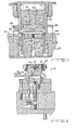
- Figure 1A is a partially broken-away and partially sectioned front elevational view of the blanking and forming die station area of a shell press;
- Figure 1 B is an extension of the right hand side of the shell press of Figure 1A illustrating an air transfer apparatus extending between a blanking and forming die station and a curling die station incorporating a pneumatic transfer system;
- Figure 2 is an enlarged, fragmentary, sectional view of a blanking and forming die station illustrating a blanked and formed shell ready for ejection therefrom;
- Figure 3 is a top plan view of a portion of an air transfer apparatus;
- Figure 4 is a cross-sectional view of Figure 3 taken along line 4-4 and viewed in the direction of the arrows;
- Figure 5 is a cross-sectional view of Figure 3 taken along line 5-5 viewed in the direction of the arrows and illustrates the position of an uncurled shell being conveyed;
- Figure 6 is an enlarged, fragmentary, sectional view of the air transfer apparatus;
- Figure 7 is a cross-sectional view of Figure 6 taken along line 7-7 and viewed in the direction of the arrows;
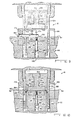
- Figure 8 is a sectional view of the curling die station depicting an uncurled shell in a stationary position out of the die station and a curled shell being ejected from the die station;
- Figure 9 is a view similar to Figure 8 with the uncurled shell entering the curling die station;
- Figure 10 is similar to Figure 9 illustrating the shell being curled by the die station; and
- Figure 11 is similar to Figure 10 illustrating a curled shell in a position for ejectment from the curling die station.
- Referring now to Figs. 1A and 1B the relevant portion of
shell press 12 is shown comprising blanking and formingdie station 14,air conveyor assembly 16, and curling diestation 18. Not shown is a strip stock feeder which feeds strip stock 20 to shellpress 12 and a scrap cutter for collecting the skeleton of strip stock 20. - Continuing to refer to Figs. 1A and 1B, blanking and forming
die station 14 comprises stationary bolster 22 secured to a press bed (not shown) and cutting die retainer assembly 24 secured on the upper surface thereof. Lower formingdie 26, the cross section of which is circular in a plain parallel to tin line 28, is securely mounted within cutting die retainer assembly 24. Bolster 22 and cutting die retainer assembly 24 are rigidly connected to the shell press frame (not shown). Lower formingdie 26 also includes anannular bead portion 30, which forms a correspondingly shapedbead portion 32 inshell 66. - Double
action slide assembly 35 comprises blankingslide 36 slidably received on shell press posts (not shown) and formingslide 38 slidably guided by blankingslide 36.Slides slide 36 ishousing assembly 40, which is slidably disposed with respect tospindle 42 and which retains punch 44 for slidable movement relative thereto. Air pressure fromair passage 46 yieldably and continuously urges punch 44 downwardly towards annular cutting die 48 in cutting die retainer assembly 24. - Upper forming
die 50 is rigidly connected to spindle 42 by retainingrod 52, which is threadedly secured at its lower end to forming die 50 and held againstspindle 42 at its upper end bynut 54.Spindle 42 is secured totop plate 56, which is connected to formingslide 38. Adowel 58 prevents rotation between formingdie 38 andspindle 42, and forming die 50 has anannular bead portion 60 about its periphery. - Referring now to Figs. 1A, 1B, and 2,
ejector mechanism 62 hasejector bar 64 in a ready position to eject blanked and formedshell 66 from blanking and formingdie station 14. When blanked and formedshell 66 is positioned as indicated in Figure 2 during the shell press cycle,ejector bar 64 is positively moved byejector mechanism 62 to a position therein it contacts shell 66 and thereafter is positively, rapidly accelerated to ejectshell 66 fromdie station 14 upwardly alongincline 68 toair conveyor assembly 16. - Referring to Figs. 1A, 1B, 3 and 7,
air conveyor assembly 16 comprises elongatedguide track 70, hollowtube 72 extending the length ofguide track 70, shapedopenings 74 disposed inhollow tube 72, and a source of high pressure air flow (not shown) connected to hollowtube 72 by asuitable connector 76. Although the disclosure is concerned with the conveyance and subsequent shaping of asingle shell 66, it is possible to fully contemplate a plurality ofshells 66 being blanked and formed for conveyance along at least twoguide tracks 70 positioned one on top of the other to a plurality of curling diestations 18. - In Figs. 1A, 1B, 5, a
support plate 78 extends between blanking and formingdie station 14 and curling diestation 18 and hasincline 68 secured to its left hand end portion byscrews 80 received through incline holes 82 and threadedhole 84 insupport plate 78.Incline 68 has a narrow neck portion 86 (Fig. 3) for ease of installation only, and upwardly facing surface 88 (Fig. 4) ofincline 68 is formed by a tapering end section ofguide track 70, which is secured to supportplate 78 byscrews 90 received through guide track holes 92 and threaded holes (not shown) insupport plate 78. - Viewing Figs. 3 and 7,
guide track 70 has alower surface 94 with agroove 96 centrally disposed longitudinally therein. Secured within the length ofgroove 96 ishollow tube 72 having oneend 100 closed and the other end 102 (Fig. 1 B) connected toconnector 76 to supply high pressure air flow through the length ofhollow tube 72. The very small diameter ofhollow tube 72 in relation to the width oflower surface 94 and the diameter of ashell 66 is important. This allowshollow tube 72 to be easily installed in narrow spaces, for example, between guide tracks positioned one upon the other to provide fluid conveyance of shells from one area to a second area withinshell press 12.Hollow tube 72 has a plurality of shapedopenings 74 uniquely stamped therein. Each stamped portion 104 (Figs. 6, 7) ofhollow tube 72 has aconcave surface 106 and aconvex surface 108, which faces generally inwardly ofhollow tube 72. Consequently, when a supply of high pressure air is provided inhollow tube 72, a flow of high pressure air is discharged through each of the shapedopenings 74 providing generally perpendicular and generally parallel velocity components relative tolower surface 94, whereby ashell 66 may be lifted upwardly and moved alonglower surface 94 in the direction of the parallel velocity components. To confineshells 66, opposite side walls 110 (Fig. 5) upstand fromlower surface 94 and eachside wall 110 has an overhangingextension 112 inwardly disposed overlower surface 94.Side walls 110 are spaced apart a distance slightly greater than the diameter of ashell 66, and remote ends 114 of overhangingextensions 112 are spaced apart a distance slightly less than the diameter ofshell 66.Side walls 110 and overhangingextensions 112 permit ashell 66 to be fluid conveyed overlower surface 94 in a manner depicted in Fig. 5. Note thatshell 66 is lifted abovelower surface 94 by the perpendicular velocity components exiting shapedopenings 74 and moved alonglower surface 94 by the parallel velocity components exiting shapedopenings 74. - Referring to Figs. 1B, 8 and 11, curling
die station 18 comprises curlingdie retainer assembly 116, lower curling die 118,liftout device 120, upper curling die 122, andsleeve 124. Curling dieretainer assembly 116 is securely mounted to stationary bolster 22 and has lower curling die 118 andliftout device 120 included therein. - Lift out
device 120 comprises annular lift outelement 126 slidably received within curling dieretainer assembly 116 and about lower curling die 118. Lift outelement 126 is also receivable withincircular groove 130 in bolster 22, however, lift outelement 126 is biased upwardly byannular spring 128 disposed withingroove 130. Lift outarm 132 is slidably received withinopening 136, which has a narrowupper portion 138 and a widerlower portion 140. Lift outarm 132 hascylindrical seat 134 secured to its upper end, and asmall piston 142 secured to its lower end inlower portion 140 ofopening 136. Lift outarm 132 is biased upwardly by spring 144, which is disposed belowpiston 142 and in openinglower portion 140 andcylindrical bore 146 in bolster 22. - Slidably disposed in upper curling die 122 is piston' 148 which has a
narrow midportion 150 slidably received withinopening 152,upper portion 154 slidably received withinopening 156, andlower portion 158 slidably received withinopening 160. Two 0-ring seals 162,164 are disposed inrespective grooves upper portion 154, respectively. A source (not shown) of air provides air under pressure tospace 170 defined by opening 156 in upper curling die 122 and slide opening 172 in which upper curling die 122 is slidably received. -
Sleeve 124 has opening 174 disposed in its side and vertically aligned with guide tracklower surface 94, and anangled opening 176 disposed in its side just slightly belowopening 174.Opening 174 has vertical and lateral dimensions sufficient to allow a blanked and formedshell 66 to pass therethrough into curlingdie station 18.Conduit 178 is disposed insupport 180 of curling dieretainer assembly 116 and has a source (not shown) of air flow connected to it opposite end. A limit switch (not shown) in curlingdie station 18 causes the source of air connected to the opposite end ofconduit 178 to emit a pulse of air flow throughconduit 178 whenangled opening 176 becomes aligned therewith (Fig. 8). Disposed insleeve 124 on its side opposite opening 174 and just slightly below opening 174 is opening 182 which has vertical and lateral dimensions sufficient for the ejection of a curledshell 188 therethrough. -
Guide track 70 is connected to support 180, which has ahole 184 disposed therein to allow a conveyed blanked and formedshell 66 to pass therethrough into curlingdie station 18.Support 180 has asecond hole 186 disposed therein to allow an ejected curledshell 188 to pass therethrough for further conveyance byair conveyor assembly 16. - Fig. 9 illustrates a blanked and formed
shell 66 being received within curlingdie station 18 and it should be noted that theupper surface 190 ofseat 134 is substantially coplanar with guide tracklower surface 94 andsupport hole 184 so thatshell 66 may be smoothly conveyed within curlingdie station 18. Likewise, Fig. 8 illustrates a curledshell 188 being ejected from curlingdie station 18, and it should be noted thatupper surface 190 is substantially co-planar withsupport hole 186 andlower surface 94 ofair conveyor assembly 16. - Upon receiving a portion of strip stock 20, blanking and forming
die station 14 blanks and formed ashell 66 andejector mechanism 62 ejects shell 66 onto guide tracklower surface 94 ofair conveyor assembly 16. Blanked and formedshell 66 is then conveyed from blanking and formingdie station 14 to curlingdie station 18 by the air jets having perpendicular and parallel velocity components directed through shapedopenings 74 ofhollow tube 72. Fig. 5 illustrates the position ofshell 66 inair conveyor assembly 16 during transport and it may be seen thatshell 66 has been lifted by the perpendicular velocity components so thatshell bead portion 32 is in contact with overhangingextension 112 to preventshell 66 from being thrown fromlower surface 94, and the parallel velocity components conveyshell 66 overlower surface 94 to curlingdie station 18. - Fig. 8 illustrates curling
die station 18 when the crankshaft (not shown) ofshell press 12 at at about 0) of crankshaft rotation. Consequently, blanked and formedshell 66 is shown in its position relative to curlingdie station 18 at about 0¼ crankshaft rotation, and the previous shell is shown as curledshell 188. - Beginning at approximately 0¼ crankshaft rotation, blanked and formed
shell 66 is positioned as illustrated in Fig. 8 in abutment withsleeve 124. As the crankshaft,continues to rotate, blankingslide 36 is moved downwardly and at approximately 67) crankshaft rotation (Fig. 9)sleeve 124 has moved downwardly to alignsleeve opening 174 withsupport hole 184 to permitshell 66 to be fluidly conveyed throughhole 184, opening 174, and into curlingdie station 18 so thatshell 66 is centrally positioned onupper surface 190 ofseat 134. Throughout this evolution,space 170 has a supply of air therein at a predetermined pressure tobias piston 148 downwardly as depicted in Fig. 8. - Fig. 10 illustrates curling
die station 18 at approximately 1804 crankshaft rotation. During crankshaft rotation from about 67t to about 180¼, pistonlower portion 158 contacts the upper surface ofshell 66 to firmly hold it in place during the curling operation. As blankingslide 36 continues to move downwardly, lower curling die 118 is forced downwardly against the spring forces ofsprings 128, 144. Aftersprings 128, 144 have been fully compressed, upper curling die 122 is forced downwardly by blankingslide 36 under a force that is greater than the force applied againstpiston 148 by the air inspace 170. The greater force supplied by blankingslide 36 to upper curling die 122 causes it to curlshell bead portion 32 againstinner curling surface 192 ofsleeve 124. Just shortly before this curling operation, lift outarm 132 has fully compressed spring 144 so that further downward movement byseat 134 is prevented. Annular lift outelement 126 then moves downwardly a small distance againstspring 128 to allow dieannular bead portion 196 to fully seat with dieannular bead portion 194 to curlshell bead portion 32 againstinner curling surface 192. - As the crankshaft rotates from about 1804 to approximately 2644, the position of curled
shell 188 within curlingdie station 18 is as illustrated in Fig. 11. As the crankshaft begins to rotate past approximately 180), blankingslide 36 begins to move upwardly to a position where the force exerted by it on upper curling die 122 becomes less than the force exerted againstpiston 148 by the air withinspace 170. At this particular point, and as blankingslide 36 continues to move upwardly, upper curling die 122 moves upwardly so that dieannular bead portion 196 separates from curledshell 188 while pistonlower portion 158 remains forced against the upper surface ofshell 188. Upon further upward movement by blankingslide 36, lower curling die 118 is stopped from further upward movement whileliftout element 126 andliftout arm 132 moves upwardly under the spring force exerted bysprings 128, 144, respectively. This causes the dieannular bead portion 194 to separate fromshell bead portion 32, and at this point curledshell 188 is being firmly held byseat 134 and pistonlower portion 158. - As the crankshaft approaches approximately 2644 rotation, blanking
slide 36 continues to move upwardly to draw pistonlower portion 158 away from the upper surface of curledshell 188 as depicted in Fig. 11, so that curledshell 188 now rests on lift outelement 126 andupper surface 190 ofseat 134 as depicted in Fig. 11. - Referring again to Fig. 8, curled
shell 188 is being conveyed from curlingdie station 18 ontolower surface 94 ofair conveyor assembly 16. As the crankshaft rotates from about 2644 to about 2944,sleeve 124 moves upwardly so thatsleeve opening 182 becomes aligned with curledshell 188 andsleeve opening 176 becomes aligned withconduit 178. Shortly beforesleeve opening 176 aligns withconduit 178, a limit switch (not shown) in curlingdie station 18 is tripped to cause the source of air connected to the opposite end ofconduit 178 to emit a pulse of air flow throughconduit 178 andsleeve opening 176 against curledshell 188 to eject it throughsleeve opening 182 andsupport hole 186 ontolower surface 94 ofair conveyor assembly 16. - As the crankshaft rotates from about 294s to about 3604, curled
shell 188 is fully ejected fluidly from curlingdie station 18 and a second blanked and formedshell 66 is fluidly conveyed byair conveyor assembly 16 againstsleeve 124 to be curled by curlingdie station 18.
Claims (7)
Applications Claiming Priority (2)
| Application Number | Priority Date | Filing Date | Title |
|---|---|---|---|
| US43404682A | 1982-10-13 | 1982-10-13 | |
| US434046 | 1982-10-13 |
Publications (3)
| Publication Number | Publication Date |
|---|---|
| EP0106435A2 EP0106435A2 (en) | 1984-04-25 |
| EP0106435A3 EP0106435A3 (en) | 1984-07-18 |
| EP0106435B1 true EP0106435B1 (en) | 1987-03-25 |
Family
ID=23722596
Family Applications (1)
| Application Number | Title | Priority Date | Filing Date |
|---|---|---|---|
| EP19830303967 Expired EP0106435B1 (en) | 1982-10-13 | 1983-07-07 | Air transfer system for a shell press |
Country Status (4)
| Country | Link |
|---|---|
| EP (1) | EP0106435B1 (en) |
| JP (1) | JPS5994540A (en) |
| CA (1) | CA1226764A (en) |
| DE (1) | DE3370451D1 (en) |
Families Citing this family (7)
| Publication number | Priority date | Publication date | Assignee | Title |
|---|---|---|---|---|
| US4513600A (en) * | 1983-01-03 | 1985-04-30 | The Minster Machine Company | Cam actuated ejector for a shell press |
| US4599884A (en) * | 1984-01-16 | 1986-07-15 | Dayton Reliable Tool & Mfg. Co. | Apparatus for transferring relatively flat objects |
| US4713958A (en) * | 1986-10-30 | 1987-12-22 | Redicon Corporation | Method and apparatus for forming container end panels |
| US4770022A (en) * | 1987-02-27 | 1988-09-13 | Dayton Reliable Tool & Mfg. Co. | Method and apparatus for transferring relatively flat objects |
| US4895012A (en) * | 1987-02-27 | 1990-01-23 | Dayton Reliable Tool & Mfg. Co. | Method and apparatus for transferring relatively flat objects |
| JP2760128B2 (en) * | 1990-03-22 | 1998-05-28 | 三菱マテリアル株式会社 | Can lid discharging device |
| CN113579037A (en) * | 2021-07-29 | 2021-11-02 | 王盛 | Multi-station punching machine |
Family Cites Families (7)
| Publication number | Priority date | Publication date | Assignee | Title |
|---|---|---|---|---|
| US3537291A (en) * | 1967-10-04 | 1970-11-03 | Reynolds Metals Co | Apparatus for and method of forming an end closure for a can |
| US3645581A (en) * | 1968-11-26 | 1972-02-29 | Ind Modular Systems Corp | Apparatus and method for handling and treating articles |
| US3874740A (en) * | 1973-02-22 | 1975-04-01 | Motch Merryweather Machinery | Orienting apparatus for cap-shaped members |
| US3902347A (en) * | 1973-10-23 | 1975-09-02 | Minster Machine Co | Mechanical press, especially a cupping press |
| US3953076A (en) * | 1974-07-23 | 1976-04-27 | The Motch & Merryweather Machinery Company | Bottle conveyor |
| US3941070A (en) * | 1975-04-09 | 1976-03-02 | The Stolle Corporation | Product transfer system |
| US4315705A (en) * | 1977-03-18 | 1982-02-16 | Gca Corporation | Apparatus for handling and treating wafers |
-
1983
- 1983-06-22 CA CA000430981A patent/CA1226764A/en not_active Expired
- 1983-07-07 DE DE8383303967T patent/DE3370451D1/en not_active Expired
- 1983-07-07 EP EP19830303967 patent/EP0106435B1/en not_active Expired
- 1983-10-13 JP JP19000683A patent/JPS5994540A/en active Granted
Also Published As
| Publication number | Publication date |
|---|---|
| DE3370451D1 (en) | 1987-04-30 |
| JPS5994540A (en) | 1984-05-31 |
| EP0106435A3 (en) | 1984-07-18 |
| JPS6354460B2 (en) | 1988-10-28 |
| EP0106435A2 (en) | 1984-04-25 |
| CA1226764A (en) | 1987-09-15 |
Similar Documents
| Publication | Publication Date | Title |
|---|---|---|
| US5881593A (en) | Method and apparatus for forming a bottom-profiled cup | |
| CA2442459C (en) | Dome forming system | |
| US4364255A (en) | Controlled oriented discharge of cups from a blanking and forming press | |
| US4903521A (en) | Method and apparatus for forming, reforming and curling shells in a single press | |
| EP0649354B1 (en) | Two stage die set | |
| US7841222B2 (en) | Container end forming system | |
| US4534725A (en) | Apparatus for manufacturing ovenable paperboard articles | |
| EP0106435B1 (en) | Air transfer system for a shell press | |
| US4554814A (en) | Air transfer system and method for a shell press | |
| CA2081428C (en) | Multiple lane ironing and doming apparatus | |
| US5062287A (en) | Method and apparatus for making and transferring shells for cans | |
| US4848974A (en) | Apparatus and method for fluidized conveying flat articles | |
| EP0149184B1 (en) | Apparatus for transferring relatively flat objects | |
| EP1036607B1 (en) | Method for forming a bottom-profiled cup | |
| US6766677B1 (en) | Die curl assembly | |
| US3469432A (en) | Pneumatic feeding device | |
| EP0438106B1 (en) | Method and apparatus for making & transferring shells for cans | |
| JPH07110389B2 (en) | Tool for press and shell manufacturing method for manufacturing shell for can end, etc. | |
| JPH10277659A (en) | Method and device for forming a cup having irregular shaped bottom | |
| GB2102367A (en) | Aerodynamic transfer system for progressive manufacturing apparatus | |
| KR20020060896A (en) | steel-can opener's auto arraying and feeding apparatus |
Legal Events
| Date | Code | Title | Description |
|---|---|---|---|
| PUAI | Public reference made under article 153(3) epc to a published international application that has entered the european phase |
Free format text: ORIGINAL CODE: 0009012 |
|
| AK | Designated contracting states |
Designated state(s): DE FR GB IT SE |
|
| PUAL | Search report despatched |
Free format text: ORIGINAL CODE: 0009013 |
|
| AK | Designated contracting states |
Designated state(s): DE FR GB IT SE |
|
| RHK1 | Main classification (correction) |
Ipc: B21D 51/44 |
|
| 17P | Request for examination filed |
Effective date: 19840918 |
|
| GRAA | (expected) grant |
Free format text: ORIGINAL CODE: 0009210 |
|
| AK | Designated contracting states |
Kind code of ref document: B1 Designated state(s): DE FR GB IT SE |
|
| PG25 | Lapsed in a contracting state [announced via postgrant information from national office to epo] |
Ref country code: SE Effective date: 19870325 |
|
| REF | Corresponds to: |
Ref document number: 3370451 Country of ref document: DE Date of ref document: 19870430 |
|
| ITF | It: translation for a ep patent filed | ||
| ET | Fr: translation filed | ||
| PLBE | No opposition filed within time limit |
Free format text: ORIGINAL CODE: 0009261 |
|
| STAA | Information on the status of an ep patent application or granted ep patent |
Free format text: STATUS: NO OPPOSITION FILED WITHIN TIME LIMIT |
|
| 26N | No opposition filed | ||
| PG25 | Lapsed in a contracting state [announced via postgrant information from national office to epo] |
Ref country code: GB Effective date: 19880707 |
|
| GBPC | Gb: european patent ceased through non-payment of renewal fee | ||
| PG25 | Lapsed in a contracting state [announced via postgrant information from national office to epo] |
Ref country code: FR Free format text: LAPSE BECAUSE OF NON-PAYMENT OF DUE FEES Effective date: 19890331 |
|
| PG25 | Lapsed in a contracting state [announced via postgrant information from national office to epo] |
Ref country code: DE Effective date: 19890401 |
|
| REG | Reference to a national code |
Ref country code: FR Ref legal event code: ST |