US5136606A - Discharge tube for a gas laser device - Google Patents
Discharge tube for a gas laser device Download PDFInfo
- Publication number
- US5136606A US5136606A US07/439,023 US43902390A US5136606A US 5136606 A US5136606 A US 5136606A US 43902390 A US43902390 A US 43902390A US 5136606 A US5136606 A US 5136606A
- Authority
- US
- United States
- Prior art keywords
- discharge tube
- discharge
- capacitive load
- load medium
- electrodes
- Prior art date
- Legal status (The legal status is an assumption and is not a legal conclusion. Google has not performed a legal analysis and makes no representation as to the accuracy of the status listed.)
- Expired - Fee Related
Links
Images


Classifications
-
- H—ELECTRICITY
- H01—ELECTRIC ELEMENTS
- H01S—DEVICES USING THE PROCESS OF LIGHT AMPLIFICATION BY STIMULATED EMISSION OF RADIATION [LASER] TO AMPLIFY OR GENERATE LIGHT; DEVICES USING STIMULATED EMISSION OF ELECTROMAGNETIC RADIATION IN WAVE RANGES OTHER THAN OPTICAL
- H01S3/00—Lasers, i.e. devices using stimulated emission of electromagnetic radiation in the infrared, visible or ultraviolet wave range
- H01S3/09—Processes or apparatus for excitation, e.g. pumping
- H01S3/097—Processes or apparatus for excitation, e.g. pumping by gas discharge of a gas laser
- H01S3/0975—Processes or apparatus for excitation, e.g. pumping by gas discharge of a gas laser using inductive or capacitive excitation
-
- H—ELECTRICITY
- H01—ELECTRIC ELEMENTS
- H01S—DEVICES USING THE PROCESS OF LIGHT AMPLIFICATION BY STIMULATED EMISSION OF RADIATION [LASER] TO AMPLIFY OR GENERATE LIGHT; DEVICES USING STIMULATED EMISSION OF ELECTROMAGNETIC RADIATION IN WAVE RANGES OTHER THAN OPTICAL
- H01S3/00—Lasers, i.e. devices using stimulated emission of electromagnetic radiation in the infrared, visible or ultraviolet wave range
- H01S3/02—Constructional details
- H01S3/03—Constructional details of gas laser discharge tubes
Definitions
- the present invention relates to a discharge tube for a high-speed axial-flow type discharge pumping gas laser device utilizing a high-frequency discharge, and more particularly, to a configuration of an electrode portion of a discharge tube.
- FIG. 3 is a conceptual diagram illustrating a configuration of electrodes of a cylindrical discharge tube according to the prior art, wherein 1 denotes a discharge tube, and 2a and 2b denote metal electrodes arranged along the outer periphery of the tubular wall of the discharge tube 1 and utilizing the tubular wall as a capacitive load.
- a high-frequency electric power of 2 MHz is supplied from a high-frequency, power supply 3, provided outside the discharge tube 1, through the electrodes to a laser gas flow 4 passing through the interior of the discharge tube 1 at a high speed.
- Numeral 5a schematically illustrates a transverse mode of the laser beam produced by this discharge pumping means. This transverse mode is a multimode, as explained hereinafter.
- FIG. 3 Optical elements and other elements necessary for a laser oscillator to produce a laser beam are omitted from FIG. 3.
- FIG. 4 is a sectional view of the discharge tube in FIG. 3.
- the electrodes 2a and 2b are arranged on the outer periphery of the discharge tube 1, the closer they are to the tubular wall of the discharge tube away from the center thereof, the shorter the discharging distance between the opposed electrodes 2a and 2b, and thus the electric field is concentrated at the side edges of the electrodes 2a and 2b. Accordingly, a discharge current is liable to be concentrated at both ends of the discharge tube 1 and thus the current density per unit volume is large.
- the distribution of the electric field strength is indicated by electric lines of force 6, and the laser active region is indicated at 7 in FIG. 4.
- the laser oscillation gain is lower at the center of the discharge tube than at the outer portions thereof, and thus a single-mode laser beam usable for a laser machining operation cannot be obtained. Accordingly, a multimode transverse mode of the laser beam is used, as indicated at 5a in FIG. 3.
- the present invention has been created in view of the above circumstances, and an object thereof is to provide a discharge tube for a gas laser device by which the distribution of a current density, and thus a laser oscillation gain within a discharge tube, is made uniform to obtain a single mode laser beam able to be used for a laser machining operation.
- a discharge tube for a high-speed axial-flow type discharge pumping gas laser device in which the axis of a laser gas flow and the axis of a laser oscillation are in alignment and are perpendicular to the direction of discharge for high-frequency discharge pumping, the discharge tube being characterized in that a capacitive load medium under metal electrodes has convexly curved faces opposed to each other and constitutes a discharge tube.
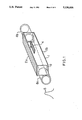
- FIG. 1 is a perspective view of a discharge tube for a gas laser device according to an embodiment of the present invention
- FIG. 2 is a sectional view of the discharge tube shown in FIG. 1;
- FIG. 3 is a conceptual diagram illustrating a configuration of electrodes of a prior art cylindrical discharge tube.
- FIG. 4 is a sectional view of the discharge tube shown in FIG. 3.
- FIG. 1 is a perspective view of a discharge tube for a gas laser device according to an embodiment of the invention, wherein 1 denotes a discharge tube, and 2a and 2b denote metal electrodes made of copper, aluminum, or the like.
- the electrodes 2a and 2b are bonded to the outer wall of the discharge tube 1 by silver paste or the like, and are further secured by a band or the like, not shown.
- Numeral 4 denotes a flow of a gas, which is a mixture of CO 2 , N 2 , and He.
- the gas is circulated at a speed of about 100 m/sec by a Roots blower or the like, not shown.
- Numeral 9 denotes a capacitive load medium which constitutes the discharge tube and which is formed by fusing quartz and drawing it in a mold. The section of the capacitive load medium 9 will be described in detail later.
- Numerals 8a and 8b denote flanges for the ends of the discharge tube, having an aperture (restriction) effect for converting the laser beam mode into a circular mode suitable for machining. The flanges are fusion bonded to the capacitive load medium 9.
- each discharge tube flange is set to a value smaller than the minimum gap between faces 9a and 9b of the capacitive load medium.
- the flanges are not provided with any electrodes.
- a high-frequency electric power of about 2 MHz is supplied to the electrodes from a high-frequency power supply, not shown, provided outside the discharge tube 1, to effect a discharge pumping of the gas flow 4 for the oscillation and amplification of the laser beam.
- the electrodes constituted by the metal electrodes 2a and 2b and the capacitive load medium 9 must be positioned diametrically opposite to each other to within ⁇ 1 degree.
- the capacitive load medium is provided with symmetrical convex faces, whereby the concentration of the electric field strength at the edges of the electrodes of the discharge tube can be restrained, the discharge is stabilized, and the distribution of the current density within the discharge tube is made uniform.
- the distribution of the laser oscillation gain within the discharge tube is made uniform, whereby a single-mode laser beam is obtained and thus a satisfactory laser machining can be carried out.
Abstract
A discharge tube for a high-speed axial-flow type discharge pumping gas laser device is provided, in which a capacitive load medium (9) under metal electrodes (2a, 2b) has convexly curved faces opposed to each other and constitutes a discharge tube. With this construction, the distribution of a laser oscillation gain within the discharge tube (1) is made uniform, and a single-mode laser beam is obtained.
Description
The present invention relates to a discharge tube for a high-speed axial-flow type discharge pumping gas laser device utilizing a high-frequency discharge, and more particularly, to a configuration of an electrode portion of a discharge tube.
FIG. 3 is a conceptual diagram illustrating a configuration of electrodes of a cylindrical discharge tube according to the prior art, wherein 1 denotes a discharge tube, and 2a and 2b denote metal electrodes arranged along the outer periphery of the tubular wall of the discharge tube 1 and utilizing the tubular wall as a capacitive load. A high-frequency electric power of 2 MHz is supplied from a high-frequency, power supply 3, provided outside the discharge tube 1, through the electrodes to a laser gas flow 4 passing through the interior of the discharge tube 1 at a high speed. Numeral 5a schematically illustrates a transverse mode of the laser beam produced by this discharge pumping means. This transverse mode is a multimode, as explained hereinafter.
Optical elements and other elements necessary for a laser oscillator to produce a laser beam are omitted from FIG. 3.
FIG. 4 is a sectional view of the discharge tube in FIG. 3. As will be understood from FIG. 4, because the electrodes 2a and 2b are arranged on the outer periphery of the discharge tube 1, the closer they are to the tubular wall of the discharge tube away from the center thereof, the shorter the discharging distance between the opposed electrodes 2a and 2b, and thus the electric field is concentrated at the side edges of the electrodes 2a and 2b. Accordingly, a discharge current is liable to be concentrated at both ends of the discharge tube 1 and thus the current density per unit volume is large.
The distribution of the electric field strength is indicated by electric lines of force 6, and the laser active region is indicated at 7 in FIG. 4.
According to the prior art, the laser oscillation gain is lower at the center of the discharge tube than at the outer portions thereof, and thus a single-mode laser beam usable for a laser machining operation cannot be obtained. Accordingly, a multimode transverse mode of the laser beam is used, as indicated at 5a in FIG. 3.
The present invention has been created in view of the above circumstances, and an object thereof is to provide a discharge tube for a gas laser device by which the distribution of a current density, and thus a laser oscillation gain within a discharge tube, is made uniform to obtain a single mode laser beam able to be used for a laser machining operation.
To achieve the above object, according to the present invention, there is provided a discharge tube for a high-speed axial-flow type discharge pumping gas laser device in which the axis of a laser gas flow and the axis of a laser oscillation are in alignment and are perpendicular to the direction of discharge for high-frequency discharge pumping, the discharge tube being characterized in that a capacitive load medium under metal electrodes has convexly curved faces opposed to each other and constitutes a discharge tube.
Since the capacitive load medium under the metal electrodes has convex faces, the discharge current and the distribution of the oscillation gain are made uniform, whereby a single-mode laser beam can be obtained.
FIG. 1 is a perspective view of a discharge tube for a gas laser device according to an embodiment of the present invention;
FIG. 2 is a sectional view of the discharge tube shown in FIG. 1;
FIG. 3 is a conceptual diagram illustrating a configuration of electrodes of a prior art cylindrical discharge tube; and
FIG. 4 is a sectional view of the discharge tube shown in FIG. 3.
An embodiment of the present invention will be described with reference to the drawings.
FIG. 1 is a perspective view of a discharge tube for a gas laser device according to an embodiment of the invention, wherein 1 denotes a discharge tube, and 2a and 2b denote metal electrodes made of copper, aluminum, or the like. The electrodes 2a and 2b are bonded to the outer wall of the discharge tube 1 by silver paste or the like, and are further secured by a band or the like, not shown.
Numeral 4 denotes a flow of a gas, which is a mixture of CO2, N2, and He. The gas is circulated at a speed of about 100 m/sec by a Roots blower or the like, not shown.
Numeral 9 denotes a capacitive load medium which constitutes the discharge tube and which is formed by fusing quartz and drawing it in a mold. The section of the capacitive load medium 9 will be described in detail later. Numerals 8a and 8b denote flanges for the ends of the discharge tube, having an aperture (restriction) effect for converting the laser beam mode into a circular mode suitable for machining. The flanges are fusion bonded to the capacitive load medium 9.
The aperture of each discharge tube flange is set to a value smaller than the minimum gap between faces 9a and 9b of the capacitive load medium. The flanges are not provided with any electrodes.
A high-frequency electric power of about 2 MHz is supplied to the electrodes from a high-frequency power supply, not shown, provided outside the discharge tube 1, to effect a discharge pumping of the gas flow 4 for the oscillation and amplification of the laser beam.
Optical components such as mirrors are omitted from the figure.
FIG. 2 is a sectional view of the discharge tube of FIG. 1, wherein 2a and 2b denote the metal electrodes and 9 the capacitive load medium. The sectional view shows that the capacitive load medium 9 preferably has a CHANG type convex shape on the inside thereof whereby the distribution of the electric field strength between the electrodes is made uniform. The upper and lower faces 9a and 9b of the capacitive load medium generally form a hyperbola, and are symmetrical and of the same shape and size. The inside side faces of the capacitive load medium are straight while the configuration of the outside is rectangular.
The electrodes constituted by the metal electrodes 2a and 2b and the capacitive load medium 9 must be positioned diametrically opposite to each other to within ±1 degree.
According to the above construction, the distribution of the electric field strength between the electrodes is made uniform, as indicated by the electric lines of force 6, and the stability and uniformity of the discharging are enhanced. As a result, the laser oscillation gain in the laser active region 7 is made uniform, and has a circular section, as indicated by the hatching in the figure. Accordingly, a single-mode laser beam having a Gaussian distribution can be obtained. In the above description, the capacitive load medium is formed into a CHANG type shape, but similar effects can be obtained with other convex shapes by which a uniform electric field is easily obtained.
As described above, according to the present invention, the capacitive load medium is provided with symmetrical convex faces, whereby the concentration of the electric field strength at the edges of the electrodes of the discharge tube can be restrained, the discharge is stabilized, and the distribution of the current density within the discharge tube is made uniform.
Accordingly, the distribution of the laser oscillation gain within the discharge tube is made uniform, whereby a single-mode laser beam is obtained and thus a satisfactory laser machining can be carried out.
Claims (5)
1. A discharge tube for a high-speed axialflow type discharge pumping gas laser device in which the axis of a laser gas flow and the axis of a laser oscillation are in alignment and are perpendicular to the direction of discharge for high-frequency discharge pumping,
said discharge tube comprising a capacitive load medium under metal electrodes, said capacitive load medium having convexly curved faces opposed to each other and flanges provided at both ends of said discharge tube, each of said flanges having a circular aperture with an inner diameter smaller than a minimum discharge gap to obtain a circular beam mode and whereby said convex faces of said capacitive load medium results in concentration of electric field strength at edges of the electrodes of said discharge tube being restrained such that said discharge tube is stabilized and distribution of current density within said discharge tube is uniform.
2. A discharge tube according to claim 1, wherein said curved faces of said capacitive load medium are symmetrical and of the same shape.
3. A discharge tube for a high-speed axial-flow type discharge pumping gas laser device in which the axis of a laser gas flow and the axis of a laser oscillation are in alignment and are perpendicular to the direction of discharge for high-frequency discharge pumping, said discharge tube comprising:
a capacitive load medium having a hollow interior provided with a pair of opposed, convexly curved faces and a pair of opposed metal electrodes mounted on the exterior of said capacitive load medium, each of said metal electrodes being positioned on the exterior of one of said curved faces whereby said curved faces are between said electrodes; and
flanges provided at both ends of said discharge tube, each of said flanges having a circular aperture with an inner diameter smaller than a medium discharge gap to obtain a circular beam mode and whereby convex faces of said capacitive load medium results in concentration of electric field strength at edges of the electrodes of said discharge tube being restrained such that said discharge tube is stabilized and distribution of current density within said discharge tube is uniform.
4. A discharge tube according to claim 3, wherein said curved faces of said capacitive load medium are symmetrical and of the same shape.
5. A discharge tube according to claim 3, wherein said hollow interior is further provided with a pair of opposed flat faces.
Applications Claiming Priority (2)
| Application Number | Priority Date | Filing Date | Title |
|---|---|---|---|
| JP63086547A JPH01258482A (en) | 1988-04-08 | 1988-04-08 | Discharge tube for gas laser device |
| JP63-086547 | 1988-04-08 |
Publications (1)
| Publication Number | Publication Date |
|---|---|
| US5136606A true US5136606A (en) | 1992-08-04 |
Family
ID=13890030
Family Applications (1)
| Application Number | Title | Priority Date | Filing Date |
|---|---|---|---|
| US07/439,023 Expired - Fee Related US5136606A (en) | 1988-04-08 | 1989-03-16 | Discharge tube for a gas laser device |
Country Status (4)
| Country | Link |
|---|---|
| US (1) | US5136606A (en) |
| EP (1) | EP0371138A4 (en) |
| JP (1) | JPH01258482A (en) |
| WO (1) | WO1989010017A1 (en) |
Cited By (4)
| Publication number | Priority date | Publication date | Assignee | Title |
|---|---|---|---|---|
| US6617019B2 (en) | 2000-02-07 | 2003-09-09 | Dow Global Technologies Inc. | Composite protective coating for metal surfaces |
| US20050180483A1 (en) * | 1998-11-13 | 2005-08-18 | Norbert Taufenbach | CO2 slab laser |
| WO2017192285A1 (en) * | 2016-05-05 | 2017-11-09 | Access Laser | Dielectric electrode assembly and method of manufacture thereof |
| US10593776B2 (en) | 2016-05-05 | 2020-03-17 | Auroma Technologies, Co., Llc. | Dielectric electrode assembly and method of manufacture thereof |
Citations (5)
| Publication number | Priority date | Publication date | Assignee | Title |
|---|---|---|---|---|
| US4359777A (en) * | 1981-01-22 | 1982-11-16 | The United States Of America As Represented By The Secretary Of The Army | High efficiency transversely excited electrodeless gas lasers |
| US4464760A (en) * | 1982-04-20 | 1984-08-07 | Sutter Jr Leroy V | Elongated chambers for use in combination with a transversely excited gas laser |
| US4800567A (en) * | 1986-01-29 | 1989-01-24 | Fanuc Ltd | High-frequency-discharge excited gas laser |
| US4885754A (en) * | 1986-12-23 | 1989-12-05 | Fanuc Ltd. | High frequency discharge excitation laser device |
| US4964136A (en) * | 1987-10-29 | 1990-10-16 | Fanuc Ltd | High-frequency discharge pumped laser device |
Family Cites Families (6)
| Publication number | Priority date | Publication date | Assignee | Title |
|---|---|---|---|---|
| US3745481A (en) * | 1972-06-13 | 1973-07-10 | Atomic Energy Commission | Electrodes for obtaining uniform discharges in electrically pumped gas lasers |
| JPS58168288A (en) * | 1982-03-30 | 1983-10-04 | Toshiba Corp | Carbon dioxide gas laser device |
| JPS60157277A (en) * | 1984-01-26 | 1985-08-17 | Mitsubishi Electric Corp | Axial-flow type noiseless discharge excitation gas laser device |
| JPS6161857U (en) * | 1984-09-28 | 1986-04-25 | ||
| JPS61295681A (en) * | 1985-06-25 | 1986-12-26 | Mitsubishi Electric Corp | Discharge tube of axial-flow type gas laser oscillator |
| JPS62174987A (en) * | 1986-01-29 | 1987-07-31 | Fanuc Ltd | Electrode for high-frequency excitation gas laser |
-
1988
- 1988-04-08 JP JP63086547A patent/JPH01258482A/en active Pending
-
1989
- 1989-03-16 WO PCT/JP1989/000287 patent/WO1989010017A1/en not_active Application Discontinuation
- 1989-03-16 EP EP19890903221 patent/EP0371138A4/en not_active Withdrawn
- 1989-03-16 US US07/439,023 patent/US5136606A/en not_active Expired - Fee Related
Patent Citations (5)
| Publication number | Priority date | Publication date | Assignee | Title |
|---|---|---|---|---|
| US4359777A (en) * | 1981-01-22 | 1982-11-16 | The United States Of America As Represented By The Secretary Of The Army | High efficiency transversely excited electrodeless gas lasers |
| US4464760A (en) * | 1982-04-20 | 1984-08-07 | Sutter Jr Leroy V | Elongated chambers for use in combination with a transversely excited gas laser |
| US4800567A (en) * | 1986-01-29 | 1989-01-24 | Fanuc Ltd | High-frequency-discharge excited gas laser |
| US4885754A (en) * | 1986-12-23 | 1989-12-05 | Fanuc Ltd. | High frequency discharge excitation laser device |
| US4964136A (en) * | 1987-10-29 | 1990-10-16 | Fanuc Ltd | High-frequency discharge pumped laser device |
Cited By (6)
| Publication number | Priority date | Publication date | Assignee | Title |
|---|---|---|---|---|
| US20050180483A1 (en) * | 1998-11-13 | 2005-08-18 | Norbert Taufenbach | CO2 slab laser |
| US7274722B2 (en) * | 1998-11-13 | 2007-09-25 | Norbert Taufenbach | CO2 slab laser |
| US6617019B2 (en) | 2000-02-07 | 2003-09-09 | Dow Global Technologies Inc. | Composite protective coating for metal surfaces |
| WO2017192285A1 (en) * | 2016-05-05 | 2017-11-09 | Access Laser | Dielectric electrode assembly and method of manufacture thereof |
| US10333268B2 (en) | 2016-05-05 | 2019-06-25 | Access Laser | Dielectric electrode assembly and method of manufacture thereof |
| US10593776B2 (en) | 2016-05-05 | 2020-03-17 | Auroma Technologies, Co., Llc. | Dielectric electrode assembly and method of manufacture thereof |
Also Published As
| Publication number | Publication date |
|---|---|
| WO1989010017A1 (en) | 1989-10-19 |
| EP0371138A1 (en) | 1990-06-06 |
| JPH01258482A (en) | 1989-10-16 |
| EP0371138A4 (en) | 1990-12-12 |
Similar Documents
| Publication | Publication Date | Title |
|---|---|---|
| US4520486A (en) | Gas flow laser oscillator | |
| US4331939A (en) | Gas laser device | |
| US5136606A (en) | Discharge tube for a gas laser device | |
| US4470144A (en) | Coaxial-type carbon dioxide gas laser oscillator | |
| US4821281A (en) | Hollow cathode glow discharge ring laser angular rate sensor | |
| US4780882A (en) | Optical resonator and laser | |
| JPS6342427B2 (en) | ||
| US5151916A (en) | Electric discharge tube for gas laser | |
| JPS6028288A (en) | Orthogonal gas laser oscillator | |
| US4827484A (en) | Apparatus and method for suppressing diffraction rings in a laser | |
| JPS5923582A (en) | Gas waveguide laser generator | |
| JPH02130973A (en) | Laser oscillator | |
| JP2706353B2 (en) | Gas laser oscillation device | |
| JPH04259273A (en) | High-frequency discharge electrode for orthogonal carbon dioxide laser | |
| JPH0371683A (en) | Gas laser device | |
| JPH0243780A (en) | High frequency vapor laser oscillator | |
| JPS5910078B2 (en) | How to adjust laser path length | |
| JPH03230587A (en) | Waveguide type gas laser oscillator | |
| JPS6185881A (en) | Laser oscillator | |
| JPH0541175A (en) | Helix type traveling-wave tube | |
| JPS6114780A (en) | Gas laser generator | |
| JPS6114779A (en) | Gas laser generator | |
| JPH0240978A (en) | Gas laser oscillator | |
| JPS60133772A (en) | Gas laser device | |
| BAKOWSKY | High power axial flow CO 2 laser(AXIAL GESTROEMTER HOCHLEISTUNGS CO 2-LASER)(Final Report) |
Legal Events
| Date | Code | Title | Description |
|---|---|---|---|
| AS | Assignment |
Owner name: FANUC LTD., 3580, SHIBOKUSA AZA-KOMANBA, OSHINOMUR Free format text: ASSIGNMENT OF ASSIGNORS INTEREST.;ASSIGNORS:IEHISA, NOBUAKI;YAMAZAKI, ETSUO;REEL/FRAME:005636/0344 Effective date: 19891024 |
|
| FEPP | Fee payment procedure |
Free format text: PAYOR NUMBER ASSIGNED (ORIGINAL EVENT CODE: ASPN); ENTITY STATUS OF PATENT OWNER: LARGE ENTITY |
|
| REMI | Maintenance fee reminder mailed | ||
| LAPS | Lapse for failure to pay maintenance fees | ||
| FP | Lapsed due to failure to pay maintenance fee |
Effective date: 19960807 |
|
| STCH | Information on status: patent discontinuation |
Free format text: PATENT EXPIRED DUE TO NONPAYMENT OF MAINTENANCE FEES UNDER 37 CFR 1.362 |