US5129847A - Pivotal air induction for marine propulsion unit - Google Patents
Pivotal air induction for marine propulsion unit Download PDFInfo
- Publication number
- US5129847A US5129847A US07/740,988 US74098891A US5129847A US 5129847 A US5129847 A US 5129847A US 74098891 A US74098891 A US 74098891A US 5129847 A US5129847 A US 5129847A
- Authority
- US
- United States
- Prior art keywords
- duct means
- shroud
- opening
- engine
- boat
- Prior art date
- Legal status (The legal status is an assumption and is not a legal conclusion. Google has not performed a legal analysis and makes no representation as to the accuracy of the status listed.)
- Expired - Lifetime
Links
Images


Classifications
-
- B—PERFORMING OPERATIONS; TRANSPORTING
- B63—SHIPS OR OTHER WATERBORNE VESSELS; RELATED EQUIPMENT
- B63H—MARINE PROPULSION OR STEERING
- B63H20/00—Outboard propulsion units, e.g. outboard motors or Z-drives; Arrangements thereof on vessels
- B63H20/24—Arrangements, apparatus and methods for handling exhaust gas in outboard drives, e.g. exhaust gas outlets
- B63H20/245—Exhaust gas outlets
-
- F—MECHANICAL ENGINEERING; LIGHTING; HEATING; WEAPONS; BLASTING
- F02—COMBUSTION ENGINES; HOT-GAS OR COMBUSTION-PRODUCT ENGINE PLANTS
- F02B—INTERNAL-COMBUSTION PISTON ENGINES; COMBUSTION ENGINES IN GENERAL
- F02B61/00—Adaptations of engines for driving vehicles or for driving propellers; Combinations of engines with gearing
- F02B61/04—Adaptations of engines for driving vehicles or for driving propellers; Combinations of engines with gearing for driving propellers
- F02B61/045—Adaptations of engines for driving vehicles or for driving propellers; Combinations of engines with gearing for driving propellers for outboard marine engines
Definitions
- Outboard motors are designed to minimize the likelihood of taking water into the engine during rain or high sea conditions.
- the engine shrouds are designed to provide such protection.
- Large outboard motors are likely to be used on large boats designed for offshore operation where sea conditions can be severe. It is not desirable to operate such boats with standard or conventional high (20 inch) transoms which can allow a following sea to enter the boat. Therefore, such boats typically mount an outboard on a bracket behind an extra high transom.
- In order to provide combustion air for the engine such outboards have sometimes been provided with a flexible air supply hose or duct connected between the engine shroud and the transom and extending through the transom to supply air from the cockpit of the boat.
- tilting and turning of the motor involves flexure of the duct which adds to the tilting and steering effort.
- the invention provides a marine propulsion device comprising a propulsion unit including an internal combustion engine, a shroud substantially enclosing the engine, and duct means having a first end communicating with the shroud and an opposite second end being adapted for connection to an opening in the transom of a boat to enable the engine to draw combustion air from the interior of the boat, the duct means including a flexible portion and a rigid portion.
- the invention also provides an outboard motor comprising an engine including a power head and a lower propulsion unit, a cover assembly for the engine including a lower pan-like cover and an upper dome-like cover enclosing the power head, a combustion air opening in the cover assembly, rigid duct means rotatably connected to the cover assembly at the opening, and flexible duct means having a first end connected to the rigid duct means and a second end adapted for connection to an opening in the transom of a boat to enable the engine to draw combustion air from the interior of the boat.
- the invention also provides a marine propulsion device comprising a propulsion unit including an internal combustion engine, a shroud substantially enclosing the engine and including therein a combustion air opening, rigid duct means opening upwardly into the interior of the shroud and being rotatably connected to the shroud for rotation about a generally vertical axis, and flexible duct means having a first end connected to the rigid duct means and a second end adapted for connection to an opening in the transom of a boat to enable the engine to draw combustion air from the interior of the boat.
- the invention also provides a marine propulsion device comprising a mounting bracket assembly, a propulsion unit including an internal combustion engine and rotatably connected to the mounting bracket assembly for rotation relative to the mounting bracket assembly about a generally vertical steering axis, a shroud substantially enclosing the engine and including therein a combustion air opening generally co-axial with the steering axis, and duct means opening downwardly through the shroud into the interior thereof at the opening and being rotatably connected to the shroud for rotation about the steering axis, the duct means being adapted for connection to an opening in the transom of a boat to enable the engine to draw combustion air from the interior of the boat.
- the invention also provides a marine propulsion device comprising a mounting bracket assembly adapted to be mounted on a boat transom for pivotal movement relative to the boat transom about a generally horizontal tilt axis, a propulsion unit including an internal combustion engine and being connected to the mounting bracket assembly for common pivotal movement with the mounting bracket assembly about the tilt axis, a shroud substantially enclosing the engine and including therein a combustion air opening, flexible duct means including a turret rotatably connected to the shroud at the opening, rigid duct means adapted for connection to an opening in the transom of the boat to enable the engine to draw combustion air from the interior of the boat, and means interconnecting the flexible duct means and the rigid duct means for relative rotation therebetween about the tilt axis.
- the invention also provides a marine propulsion device comprising a mounting bracket assembly adapted to be mounted on a boat transom for pivotal movement relative to the boat transom about a generally horizontal tilt axis, a propulsion unit including an internal combustion engine and being connected to the mounting bracket assembly for common pivotal movement with the mounting bracket assembly about a tilt axis, a shroud substantially enclosing the engine and including therein a combustion air opening, flexible duct means connected to the combustion air opening, rigid duct means adapted for connection to an opening in the transom of the boat to enable the engine to draw combustion air from the interior of the boat, and means interconnecting the flexible duct means and the rigid duct means for relative rotation therebetween about the tilt axis.
- the invention also provides a marine vehicle comprising a boat including a transom having an opening therein, a propulsion unit including an internal combustion engine and being mounted on the transom, a shroud substantially enclosing the engine, and duct means having a first end communicating with the shroud and an opposite second end communicating with the opening in the transom, the duct means including a flexible portion and a rigid portion.
- FIG. 1 is a side elevation showing an outboard motor mounted on the extra high transom of a boat (shown only in part);
- FIG. 2 is a partial vertical section of the pivotal air induction assembly for the motor illustrated in FIG. 1;
- FIG. 3 is a meandering, generally horizontal section taken on line 3--3 in FIG. 2;
- FIG. 4 is a detailed section showing the manner in which the rigid duct or turret is fixed to the lower cover
- FIG. 5 is a side elevation view of an outboard motor mounted on the transom of a boat having an engine well, and of an alternative embodiment of the duct means for carrying combustion air to the engine;
- FIG. 6 is a side elevation view of an outboard motor mounted on an outrigger bracket assembly, and of another alternative embodiment of the duct means;
- FIG. 7 is a detailed cross-sectional view of the manner in which the turret shown in FIG. 6 is connected to the upper cover;
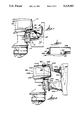
- FIG. 8 is a side elevational view of an outboard motor mounted on an outrigger bracket assembly, and of another alternative embodiment of the duct means;
- FIG. 9 is a top view, partially in cross section, of the outboard motor illustrated in FIG. 8;
- FIG. 10 is an enlarged cross-sectional view of a portion of FIG. 9;
- FIG. 11 is a side elevational view of an outboard motor mounted on an outrigger bracket assembly, and of another alternative embodiment of the duct means;
- FIG. 12 is a top view, partially in cross section, of the outboard motor of FIG. 11.
- FIG. 1 Illustrated in FIG. 1 is marine propulsion device including an outboard motor 10 having an engine 12 shown in dotted lines.
- the engine 12 drives a propeller 14 through a drive shaft, gearing, etc., not shown.
- Combustion air passes through carburetors 16 at the front of the engine 12.
- the motor 10 is mounted for steering about a vertical axis 18 at the rear of brackets 20 which pivot about the horizontal axis of pivot pins 21 supported by brackets 22 fixed to the transom 24 of the boat 26.
- the motor 10 can be pivoted about the horizontal axis 21 to raise the propeller 14 out of the water. Provision for slight movement of the motor about axis 21 for trim purposes can be made.
- High transom boats are frequently operated offshore where high sea conditions may be encountered.
- the boat transom 24 is quite high, leaving the motor 10 exposed to the sea.
- the engine 12 is protected against ingesting water by means of a cover assembly or shroud 25 which seals the engine 12 from rain and seawater and which includes a lower pan or cover 27 and an upper dome-like cover 29.
- the air for the engine 12 is drawn from inside the cockpit of the boat 26, that is, from the forward side of the transom 24, through an opening 30 through the transom 24.
- the opening 30 can, if desired, be hooded or otherwise protected against entry of water at that point.
- the marine propulsion device includes duct means having opposite first and second ends, the first end communicating with the shroud 25 and the second end being adapted for connection to and through the transom 24 to enable the engine 12 to draw combustion air from the interior of the boat 26, the duct means including a flexible portion and a rigid portion. While various suitable means could be employed for this purpose, in the preferred embodiment, such means includes a flexible duct 32, a rigid conduit 34, a flexible duct 36, and a rigid duct or turret 38.
- the short flexible duct 32 is connected between the opening 30 and the upper end of rigid conduit 34.
- the conduit 34 has an upper elbow connected to flexible duct 32, a generally vertical section 35, and a lower elbow leading aft to the flexible duct 36 which is connected to the forward end of the rigid duct or turret 38.
- the turret 38 communicates with a combustion air opening 42 in the shroud 25 and is rotatably connected to the shroud 25.
- the turret 38 has a duct portion 56 and a tubular portion projecting upwardly through the opening 42 in the lower cover 27 to position a groove 46 above the inside surface of the lower motor cover 27.
- the turret 38 includes means preventing axial movement of the tubular portion relative to the lower cover 27. While various suitable means could be employed for this purpose, in the illustrated construction, such means includes a snap ring 48 split at one place with adjacent upstanding bosses 50 apertured to receive a cotter pin 52 to keep the split ring closed, and an annular shoulder 54 engaging the outside of the lower cover 27 adjacent the opening 42. It will be noted that the shoulder 54 converges downwardly toward the turret duct portion 56.
- An annular seal 60 surrounds the shoulder 54 and engages the outside of the lower cover 27 for sealing the joint between the shoulder 54 and the lower cover 27 while permitting the turret 38 to rotate relative to the cover 27. Where there is no duct portion 56 a shoulder 58 is provided to confine the seal 60.
- the turret 38 rotates relative to the cover 27.
- the flexible duct 36 will accommodate this turning movement and can elongate as well. Rotating the turret 38 minimizes the flexure required of the flexible duct 36.
- the combustion air enters the air induction passage at 30 from the cockpit.
- the air passes down through the smooth interior of conduit 34 and enters the turret 38 where it is directed upwardly into the inside of the engine shroud 25.
- the chance of water entering the shroud 25 either with a wave breaking over the motor 10 or with momentary submerging of the transom 24 is minimized. Any water entering the shroud 25 will collect in the lower pan 27 and can be removed by any suitable pumping or draining means.
- FIGS. 5 through 12 Illustrated in FIGS. 5 through 12 are several alternative embodiments of the invention. While each of these embodiments is shown in connection with a particular outboard motor mounting arrangement, it should be understood that each embodiment, as well as the embodiment shown in FIGS. 1 through 4, can be used in connection with other mounting arrangements. For example, the duct means shown in FIG. 6 can also be used with the engine well mounting arrangement shown in FIG. 5.
- FIG. 5 Illustrated in FIG. 5 is one alternative embodiment of the invention. Shown is a marine propulsion device in the form of an outboard motor 110 similar to the motor shown in FIG. 1.
- the outboard motor 110 is mounted on a boat transom 116 by a conventional mounting bracket assembly.
- the outboard motor 110 is pivotally connected to a swivel bracket 112 for pivotal movement of the motor 110 relative to the swivel bracket 112 about a generally vertical steering axis 114.
- the swivel bracket 112 is connected to a transom bracket 113 mounted on the boat transom 116 for common pivotal movement of the motor 110 and of the swivel bracket 112 about a generally horizontal tilt axis 118, so that the motor 110 can be pivoted about the tilt axis 118 to raise the propeller out of the water.
- the boat has an engine well 120 which provides room for tilting of the outboard motor 110.
- the outboard motor 110 includes an engine 122 substantially enclosed by a shroud 124 including a lower cover 126 and an upper dome-like cover 128.
- Air for the engine 122 is drawn from inside the cockpit of the boat through duct means connected between an opening 129 in the transom 116 and a combustion air opening 130 in the lower cover 126.
- the duct means includes an airbox 132 having one end connected to the opening 129 in the transom 116 and an opposite end connected to the lower end of a flexible duct or bellow 134.
- the upper end of the flexible duct 134 is connected to the forward end of a rigid duct or turret 136, which is connected to the combustion air opening 130.
- the turret 136 has the same construction as the turret 38 illustrated in FIG. 4 and is similarly rotatably connected to the lower cover 126 for rotation about a generally vertical axis.
- the turret 136 rotates relative to the lower cover 126.
- the flexible duct 134 elongates and twists in order to accommodate this movement of the turret 136.
- the turret 136 rotates forwardly and downwardly about the tilt axis 118, and the flexible duct 134 compresses and flexes to accommodate this movement.
- FIGS. 6 and 7 Illustrated in FIGS. 6 and 7 is another alternative embodiment of the invention. Shown is an outboard motor 210 mounted on a boat transom 212 with an outrigger bracket assembly 214.
- the outrigger bracket assembly 214 includes a rearwardly extending bracket 216 fixedly mounted on the boat transom 212 and supporting a false transom 218 that is substantially parallel to the boat transom 212.
- the outboard motor 210 is mounted on the false transom 218 by a mounting bracket assembly 220 similar to the mounting bracket assembly 112 shown in FIG. 5.
- the outboard motor 210 is pivotally connected to the mounting bracket assembly 220 for steering movement relative to the mounting bracket assembly 220 about a generally vertical steering axis 222, and for pivotal movement of the outboard motor 210 relative to the false transom 218 about a generally horizontal tilt axis 224.
- the outboard motor 210 includes an engine 226 substantially enclosed by a shroud 228 including a lower cover 230 and an upper dome-like cover 232. Air for the engine 226 is drawn from inside the cockpit of the boat through duct means connected between an opening 238 in the transom and a combustion air opening 240 in the upper cover 232. The combustion air opening 240 is centered on the steering axis 222.
- the duct means includes a flexible duct or bellows 242 having one end communicating with the opening 238 in the transom and sealingly connected to the transom 212 by any suitable means.
- the other end of the flexible duct 242 is connected to the forward end of an airbox 244.
- the rearward end of the airbox 244 is fixedly attached to a turret 246 communicating with the opening 240 in the upper covering 232 and rotatably connected to the upper cover 232 for rotation about the steering axis 222.
- the connection between the turret 246 and the upper cover 232 is best illustrated in FIG. 7 and is essentially the same as the connection shown in FIG. 4. Parts of the turret 246 shown in FIG. 7 corresponding to parts shown in FIG. 4 are given the same reference numeral.
- the turret 246 is rotatably connected to the upper cover 232 for rotation relative to the upper cover 232 about the steering axis 222, the turret 246 and the remainder of the duct means do not move relative to the boat transom 212 during steering of the outboard motor 210.
- the motor 210 is turned, the turret 246 remains stationary and the upper cover 232 rotates relative to the turret 246.
- the only movement of the duct means relative to the boat transom 212 is during tilting of the outboard motor 210.
- the turret 246 and airbox 244 rotate forwardly and downwardly relative to the tilt axis 224. This movement is accommodated by the flexible duct 242 communicating between the forward end of the airbox 244 and the boat transom 212.
- FIGS. 8 through 10 Illustrated in FIGS. 8 through 10 is another alternative embodiment of the invention. Shown in FIG. 8 is an outboard motor 310 mounted on a boat transom 312 with an outrigger bracket assembly 314 identical to the outrigger bracket assembly 214 illustrated in FIG. 6.
- the outboard motor 310 is pivotally connected to a mounting bracket assembly 316 for steering movement relative to the mounting bracket assembly 316 about a generally vertical steering axis 318, and for pivotal movement of the outboard motor 310 relative to the false transom 320 about a generally horizontal tilt axis 322.
- the outboard motor 310 includes an engine 324 substantially enclosed by a shroud 326 including a lower cover 328 and an upper dome-like cover 330. Air for the engine 324 is drawn from inside the cockpit of the boat through duct means connected between an opening 332 in the transom 312 and a pair of combustion air openings 334 in the lower cover 328.
- the duct means includes a generally Y-shaped airbox 336 having its base or forward portion communicating with the opening 332 in the transom 312 and sealingly connected to the transom 312.
- the airbox 336 is connected to the transom 312 by screws, although any suitable connecting means can be used.
- the airbox 336 extends rearwardly of the boat transom 312 toward the outboard motor 310, and, at a point forward of the tilt axis 322, splits into two arms having outer ends that extend to points on the tilt axis 322 on either side of the outboard motor 310, as best shown in FIG. 9.
- each of the arms of the airbox 336 includes a circular aperture 338 centered on the tilt axis 322.
- the aperture 338 faces outwardly, although it could also face inwardly.
- Communicating with each aperture 338 and rotatably connected to the outer end of the arm is a forward turret 340.
- the connection of the forward turrets 340 to the arms of the airbox 336 is similar to the connection of the turret 38 to the lower cover illustrated in FIG. 4.
- Each forward turret 340 has a tubular portion projecting inwardly through the aperture in the arm to position a groove inside the inside surface of the arm and is retained in this position by a snap ring 342 received in the groove.
- Each forward turret 340 is also connected to a flexible duct or bellow 346 having one end connected to the forward turret 340 and an opposite end connected to a rearward turret 348 communicating with one of the combustion air openings 334 in the lower cover 328 and connected to the lower cover 328 for rotation about a generally vertical axis.
- the connection of the rearward turret 348 to the lower cover 328 is similar to the connection illustrated in FIG. 4.
- the rearward turrets 348 rotate relative to the lower cover 328 and the flexible ducts 346 flex in order to accommodate the movement about the steering axis 318 of the rearward turrets 348.
- the forward turrets 340 rotate relative to the arms of the airbox 336. During tilting there is no relative movement of the rearward turrets 348 or flexible ducts 346 with respect to the forward turrets 340.
- FIGS. 11 and 12 Illustrated in FIGS. 11 and 12 is another alternative embodiment of the invention. Shown in FIG. 11 is an outboard motor 410 mounted on a boat transom 412 with an outrigger bracket assembly 414 identical to the outrigger bracket assemblies illustrated in FIGS. 6 and 8.
- the outboard motor 410 is pivotally connected to a mounting bracket assembly 416 for steering movement relative to the mounting assembly 416 about a generally vertical steering axis 418, and for pivotal movement of the outboard motor 410 relative to the false transom 420 about a generally horizontal tilt axis 422.
- the outboard motor 410 includes an engine 424 substantially enclosed by a shroud 426. Air for the engine 424 is drawn from inside the cockpit of the boat through duct means connected between an opening 428 in the transom and a pair of combustion air openings 430 in the sides of the shroud 426.
- the duct means illustrated in FIGS. 11 and 12 is very similar to the duct means illustrated in FIGS. 8-10.
- the duct means of FIGS. 11 and 12 includes a Y-shaped airbox 432 similar to the airbox 336 shown in FIGS. 8 and 9.
- the outer end of each of the arms of the airbox 432 includes a circular aperture centered on the tilt axis 422, and communicating with the aperture and rotatably connected to the outer end of each arm is a forward turret 434.
- the connection of the forward turrets 434 to the arms of the airbox 432 is identical to the connection of the forward turrets 340 to the arms of the airbox 336 illustrated in FIG. 10. Because the apertures in the arms of the airbox 432 are centered on the tilt axis 422, the forward turrets 434 rotate relative to the arms about the tilt axis 422.
- Each forward turret 434 is also connected to a flexible duct or bellow 436 having one end connected to the forward turret 434 and an opposite end connected to the engine shroud 426 and communicating with one of the combustion air openings 430 in the sides of the shroud 426.
- the flexible ducts 436 flex in order to accommodate the movement of the combustion air openings 430 about the steering axis 418.
- the forward turrets 434 rotate relative to the arms of the box 432. During tilting there is no relative movement of the flexible ducts 436 with respect to the forward turrets 434.
Abstract
Description
Claims (41)
Priority Applications (1)
| Application Number | Priority Date | Filing Date | Title |
|---|---|---|---|
| US07/740,988 US5129847A (en) | 1984-07-16 | 1991-08-06 | Pivotal air induction for marine propulsion unit |
Applications Claiming Priority (2)
| Application Number | Priority Date | Filing Date | Title |
|---|---|---|---|
| US63140884A | 1984-07-16 | 1984-07-16 | |
| US07/740,988 US5129847A (en) | 1984-07-16 | 1991-08-06 | Pivotal air induction for marine propulsion unit |
Related Parent Applications (1)
| Application Number | Title | Priority Date | Filing Date |
|---|---|---|---|
| US07/649,163 Division US5078629A (en) | 1984-07-16 | 1991-02-01 | Pivotal air induction for marine propulsion unit |
Publications (1)
| Publication Number | Publication Date |
|---|---|
| US5129847A true US5129847A (en) | 1992-07-14 |
Family
ID=27091385
Family Applications (1)
| Application Number | Title | Priority Date | Filing Date |
|---|---|---|---|
| US07/740,988 Expired - Lifetime US5129847A (en) | 1984-07-16 | 1991-08-06 | Pivotal air induction for marine propulsion unit |
Country Status (1)
| Country | Link |
|---|---|
| US (1) | US5129847A (en) |
Cited By (12)
| Publication number | Priority date | Publication date | Assignee | Title |
|---|---|---|---|---|
| US5660571A (en) * | 1992-07-24 | 1997-08-26 | Sanshin Kogyo Kabushiki Kaisha | Muffling device for outboard propulsion machine |
| US6796859B1 (en) * | 2000-11-16 | 2004-09-28 | Bombardier Recreational Products Inc. | Air intake silencer |
| US20050051384A1 (en) * | 2003-09-10 | 2005-03-10 | Breznik Evelyn A. | Air intake silencer |
| US20070054571A1 (en) * | 2005-09-08 | 2007-03-08 | Koshiro Inaba | Watercraft |
| US7438614B2 (en) | 2005-09-20 | 2008-10-21 | Yamaha Marine Kabushiki Kaisha | Cooling system for outboard motor |
| WO2013154809A1 (en) * | 2012-04-11 | 2013-10-17 | Brunswick Corporation | Marine propulsion systems and intake air systems for marine propulsion systems |
| US20130280970A1 (en) * | 2012-04-11 | 2013-10-24 | Brunswick Corporation | Marine propulsion systems, intake air systems for marine propulsion systems, and marine propulsion systems having exhaust gas relief outlet |
| US20140057508A1 (en) * | 2012-08-24 | 2014-02-27 | Brunswick Corporation | Marine propulsion systems having exhaust gas relief outlet |
| US8834216B1 (en) | 2013-01-31 | 2014-09-16 | Brp Us Inc. | Water deflector for a marine outboard engine |
| US8858280B1 (en) | 2010-10-29 | 2014-10-14 | Brp Us Inc. | Marine engine rigging system |
| US9126664B1 (en) | 2013-03-15 | 2015-09-08 | Brunswick Corporation | Hidden outboard engine enclosures |
| US9216795B2 (en) | 2011-06-24 | 2015-12-22 | Marinemax, Inc. | Hull design with engine air flow system |
Citations (17)
| Publication number | Priority date | Publication date | Assignee | Title |
|---|---|---|---|---|
| US1846283A (en) * | 1929-02-01 | 1932-02-23 | Gen Motors Corp | Air inlet system for engines |
| US1863015A (en) * | 1927-08-13 | 1932-06-14 | Ac Spark Plug Co | Air filter |
| US2216496A (en) * | 1938-07-29 | 1940-10-01 | Kenneth H Mackay | Marine propulsion assembly |
| US2494158A (en) * | 1946-07-12 | 1950-01-10 | Hermann P Below | Outboard motor |
| US2952327A (en) * | 1953-05-11 | 1960-09-13 | Precasco Corp | Air cleaner for automobiles |
| US3136285A (en) * | 1963-01-07 | 1964-06-09 | Kiekhaefer Corp | Steering arrangement for outboard propulsion unit |
| US3151695A (en) * | 1962-05-02 | 1964-10-06 | Mack Trucks | Air cleaner seal for tilt cab vehicles |
| US3181495A (en) * | 1963-01-07 | 1965-05-04 | Kiekhaefer Corp | Coolant supply and exhaust discharge means for inboard-outboard drives |
| US3250501A (en) * | 1964-09-17 | 1966-05-10 | Kiekhaefer Corp | Outboard stern drive for boats and hydraulic shock absorber therefor |
| US3487804A (en) * | 1967-10-10 | 1970-01-06 | Brunswick Corp | Underwater propeller with airvented slip stream |
| US4080184A (en) * | 1975-04-25 | 1978-03-21 | Petersen Ross K | Engine air intake system |
| US4289488A (en) * | 1979-02-21 | 1981-09-15 | Brunswick Corporation | Stern drive gimbal arrangement |
| US4375356A (en) * | 1980-09-24 | 1983-03-01 | Outboard Marine Corporation | Arrangement for supplying air, fuel, power and control cables to a marine propulsion unit |
| US4395238A (en) * | 1981-02-20 | 1983-07-26 | Outboard Marine Corporation | Outboard motor mounting means affording upward tilting without travel of the motor forwardly of the boat transom |
| US4416475A (en) * | 1982-12-09 | 1983-11-22 | Tarrant Manufacturing Company | Flexible coupling |
| US4623313A (en) * | 1981-08-17 | 1986-11-18 | Outboard Marine Corporation | Pivotal air induction for marine propulsion device |
| US4753619A (en) * | 1985-04-11 | 1988-06-28 | Sullivan Donald K | Marine propulsion device bellows assembly |
-
1991
- 1991-08-06 US US07/740,988 patent/US5129847A/en not_active Expired - Lifetime
Patent Citations (17)
| Publication number | Priority date | Publication date | Assignee | Title |
|---|---|---|---|---|
| US1863015A (en) * | 1927-08-13 | 1932-06-14 | Ac Spark Plug Co | Air filter |
| US1846283A (en) * | 1929-02-01 | 1932-02-23 | Gen Motors Corp | Air inlet system for engines |
| US2216496A (en) * | 1938-07-29 | 1940-10-01 | Kenneth H Mackay | Marine propulsion assembly |
| US2494158A (en) * | 1946-07-12 | 1950-01-10 | Hermann P Below | Outboard motor |
| US2952327A (en) * | 1953-05-11 | 1960-09-13 | Precasco Corp | Air cleaner for automobiles |
| US3151695A (en) * | 1962-05-02 | 1964-10-06 | Mack Trucks | Air cleaner seal for tilt cab vehicles |
| US3136285A (en) * | 1963-01-07 | 1964-06-09 | Kiekhaefer Corp | Steering arrangement for outboard propulsion unit |
| US3181495A (en) * | 1963-01-07 | 1965-05-04 | Kiekhaefer Corp | Coolant supply and exhaust discharge means for inboard-outboard drives |
| US3250501A (en) * | 1964-09-17 | 1966-05-10 | Kiekhaefer Corp | Outboard stern drive for boats and hydraulic shock absorber therefor |
| US3487804A (en) * | 1967-10-10 | 1970-01-06 | Brunswick Corp | Underwater propeller with airvented slip stream |
| US4080184A (en) * | 1975-04-25 | 1978-03-21 | Petersen Ross K | Engine air intake system |
| US4289488A (en) * | 1979-02-21 | 1981-09-15 | Brunswick Corporation | Stern drive gimbal arrangement |
| US4375356A (en) * | 1980-09-24 | 1983-03-01 | Outboard Marine Corporation | Arrangement for supplying air, fuel, power and control cables to a marine propulsion unit |
| US4395238A (en) * | 1981-02-20 | 1983-07-26 | Outboard Marine Corporation | Outboard motor mounting means affording upward tilting without travel of the motor forwardly of the boat transom |
| US4623313A (en) * | 1981-08-17 | 1986-11-18 | Outboard Marine Corporation | Pivotal air induction for marine propulsion device |
| US4416475A (en) * | 1982-12-09 | 1983-11-22 | Tarrant Manufacturing Company | Flexible coupling |
| US4753619A (en) * | 1985-04-11 | 1988-06-28 | Sullivan Donald K | Marine propulsion device bellows assembly |
Cited By (16)
| Publication number | Priority date | Publication date | Assignee | Title |
|---|---|---|---|---|
| US5660571A (en) * | 1992-07-24 | 1997-08-26 | Sanshin Kogyo Kabushiki Kaisha | Muffling device for outboard propulsion machine |
| US6796859B1 (en) * | 2000-11-16 | 2004-09-28 | Bombardier Recreational Products Inc. | Air intake silencer |
| US20050051384A1 (en) * | 2003-09-10 | 2005-03-10 | Breznik Evelyn A. | Air intake silencer |
| US20070054571A1 (en) * | 2005-09-08 | 2007-03-08 | Koshiro Inaba | Watercraft |
| US7510451B2 (en) * | 2005-09-08 | 2009-03-31 | Yamaha Hatsudoki Kabushiki Kaisha | Watercraft |
| US7438614B2 (en) | 2005-09-20 | 2008-10-21 | Yamaha Marine Kabushiki Kaisha | Cooling system for outboard motor |
| US8858280B1 (en) | 2010-10-29 | 2014-10-14 | Brp Us Inc. | Marine engine rigging system |
| US9216795B2 (en) | 2011-06-24 | 2015-12-22 | Marinemax, Inc. | Hull design with engine air flow system |
| EP2836426A4 (en) * | 2012-04-11 | 2015-06-03 | Brunswick Corp | Marine propulsion systems and intake air systems for marine propulsion systems |
| US8858282B2 (en) | 2012-04-11 | 2014-10-14 | Brunswick Corporation | Marine propulsion systems and intake air systems for marine propulsion systems |
| US20130280970A1 (en) * | 2012-04-11 | 2013-10-24 | Brunswick Corporation | Marine propulsion systems, intake air systems for marine propulsion systems, and marine propulsion systems having exhaust gas relief outlet |
| WO2013154809A1 (en) * | 2012-04-11 | 2013-10-17 | Brunswick Corporation | Marine propulsion systems and intake air systems for marine propulsion systems |
| US20140057508A1 (en) * | 2012-08-24 | 2014-02-27 | Brunswick Corporation | Marine propulsion systems having exhaust gas relief outlet |
| US9051041B2 (en) * | 2012-08-24 | 2015-06-09 | Brunswick Corporation | Marine propulsion systems having exhaust gas relief outlet |
| US8834216B1 (en) | 2013-01-31 | 2014-09-16 | Brp Us Inc. | Water deflector for a marine outboard engine |
| US9126664B1 (en) | 2013-03-15 | 2015-09-08 | Brunswick Corporation | Hidden outboard engine enclosures |
Similar Documents
| Publication | Publication Date | Title |
|---|---|---|
| US4371348A (en) | Mounting for marine propulsion device located aft of boat transom | |
| US5326294A (en) | Stern drive for boats | |
| US5108325A (en) | Boat propulsion device | |
| US5129847A (en) | Pivotal air induction for marine propulsion unit | |
| US4545770A (en) | Outboard motor mounting arrangement | |
| CA1176917A (en) | Arrangement for supplying air, fuel, power and control cables to a marine propulsion unit | |
| US6280267B1 (en) | Retractable trolling motor | |
| US3893407A (en) | Inboard-outboard marine drive | |
| CA1036872A (en) | Marine propulsion device adapted for a sailboat | |
| JP3046398B2 (en) | Ship propulsion | |
| CA1172917A (en) | Outboard motor mounting means affording upward tilting without travel of the motor forwardly of the boat transom | |
| US4911666A (en) | Boat propulsion device with internal exhaust | |
| US4623313A (en) | Pivotal air induction for marine propulsion device | |
| US5078629A (en) | Pivotal air induction for marine propulsion unit | |
| EP0460373B1 (en) | Water jet propulsion boat | |
| CA1239057A (en) | Pivotal air induction for marine propulsion unit | |
| US5348500A (en) | Marine propulsion device with selectively operable secondary exhaust discharge | |
| US6279499B1 (en) | Rotational jet-drive bow thruster for a marine propulsion system | |
| JP4508353B2 (en) | Watercraft equipped with water jet propulsion device | |
| US4753619A (en) | Marine propulsion device bellows assembly | |
| GB2151197A (en) | Water pump location for marine propulsion device | |
| US5145426A (en) | Multi jet propelled watercraft | |
| US5766046A (en) | Cooling water pickup for marine propulsion unit | |
| US6287162B1 (en) | Bearing arrangement for drive shaft of water jet apparatus | |
| US6758706B2 (en) | Marine propulsion housing arrangement |
Legal Events
| Date | Code | Title | Description |
|---|---|---|---|
| STCF | Information on status: patent grant |
Free format text: PATENTED CASE |
|
| FEPP | Fee payment procedure |
Free format text: PAYOR NUMBER ASSIGNED (ORIGINAL EVENT CODE: ASPN); ENTITY STATUS OF PATENT OWNER: LARGE ENTITY |
|
| FPAY | Fee payment |
Year of fee payment: 4 |
|
| FPAY | Fee payment |
Year of fee payment: 8 |
|
| FPAY | Fee payment |
Year of fee payment: 12 |
|
| AS | Assignment |
Owner name: BOMBARDIER MOTOR CORPORATION OF AMERICA, FLORIDA Free format text: NUNC PRO TUNC ASSIGNMENT;ASSIGNOR:OUTBOARD MARINE CORPORATION;REEL/FRAME:014192/0532 Effective date: 20031211 |
|
| AS | Assignment |
Owner name: BOMBARDIER RECREATIONAL PRODUCTS INC., CANADA Free format text: ASSIGNMENT OF ASSIGNORS INTEREST;ASSIGNOR:BOMBARDIER MOTOR CORPORATION OF AMERICA;REEL/FRAME:014532/0362 Effective date: 20031218 |
|
| AS | Assignment |
Owner name: BRP US INC., WISCONSIN Free format text: ASSIGNMENT OF ASSIGNORS INTEREST;ASSIGNOR:BOMBARDIER RECREATIONAL PRODUCTS INC.;REEL/FRAME:016087/0282 Effective date: 20050131 |
|
| AS | Assignment |
Owner name: BANK OF MONTREAL, AS ADMINISTRATIVE AGENT, CANADA Free format text: SECURITY AGREEMENT;ASSIGNOR:BRP US INC.;REEL/FRAME:018350/0269 Effective date: 20060628 |