US9126664B1 - Hidden outboard engine enclosures - Google Patents
Hidden outboard engine enclosures Download PDFInfo
- Publication number
- US9126664B1 US9126664B1 US13/836,929 US201313836929A US9126664B1 US 9126664 B1 US9126664 B1 US 9126664B1 US 201313836929 A US201313836929 A US 201313836929A US 9126664 B1 US9126664 B1 US 9126664B1
- Authority
- US
- United States
- Prior art keywords
- watercraft
- transom
- enclosure
- deck
- cavities
- Prior art date
- Legal status (The legal status is an assumption and is not a legal conclusion. Google has not performed a legal analysis and makes no representation as to the accuracy of the status listed.)
- Active, expires
Links
Images


Classifications
-
- B—PERFORMING OPERATIONS; TRANSPORTING
- B63—SHIPS OR OTHER WATERBORNE VESSELS; RELATED EQUIPMENT
- B63H—MARINE PROPULSION OR STEERING
- B63H5/00—Arrangements on vessels of propulsion elements directly acting on water
-
- B—PERFORMING OPERATIONS; TRANSPORTING
- B63—SHIPS OR OTHER WATERBORNE VESSELS; RELATED EQUIPMENT
- B63H—MARINE PROPULSION OR STEERING
- B63H20/00—Outboard propulsion units, e.g. outboard motors or Z-drives; Arrangements thereof on vessels
- B63H20/02—Mounting of propulsion units
- B63H20/04—Mounting of propulsion units in a well
-
- B—PERFORMING OPERATIONS; TRANSPORTING
- B63—SHIPS OR OTHER WATERBORNE VESSELS; RELATED EQUIPMENT
- B63H—MARINE PROPULSION OR STEERING
- B63H20/00—Outboard propulsion units, e.g. outboard motors or Z-drives; Arrangements thereof on vessels
- B63H20/32—Housings
Definitions
- the present invention generally relates to marine watercrafts and more specifically to outboard engine enclosures for marine watercrafts.
- Marine watercrafts incorporate various means of propulsion including but not limited to internal combustion engines. Such engines are typically powered by a fossil fuel such as a gasoline and are configured to drive a driveshaft to which a propeller is connected. The engine therefore turns the propeller and the propeller converts the rotational power into thrust. More specifically, a pressure differential is produced between the forward and rear surfaces of the airfoil-shaped propeller, and the water is accelerated behind the blade. Marine watercrafts can utilize one or more engines depending on the size and configuration of the watercraft and desired power characteristics. For example, a small leisure craft may only require a small single engine while a large cruise liner may require several larger engines in order to provide optimal thrust and power output.
- a small leisure craft may only require a small single engine while a large cruise liner may require several larger engines in order to provide optimal thrust and power output.
- Marine watercrafts can be configured to operate with several styles of engines including, but not limited to, outboard motors, inboard motors, and inboard/outboard motors also known as stern drive motors.
- Outboard marine motors comprise a self-contained unit that includes engine, gearbox, and propeller or jet drive, designed to be affixed to the outside of the transom or rear platform of the watercraft.
- An inboard motor is an motor system wherein the engine and gearbox are mounted inside the hull of the watercraft whereby a driveshaft connects the external propeller to the gearbox.
- An inboard/outboard motor or “sterndrive” motor combines inboard power with outboard drive wherein the engine itself sits just forward of the transom while the drive unit lies outside the hull.
- the motor also provides a means for steering the watercraft as the outboard motor is designed to pivot over its mountings and thus control the direction of thrust.
- multiple outboard motors are provided on a watercraft to increase power output. These multiple outboard motors are typically linked at their mountings such that the motors pivot simultaneously in order to steer the watercraft.
- outboard motors are also configured to tilt upward and downward to control the depth to which the propeller reaches. This allows the watercraft operator to traverse waters of varying depth in that the motor can be tilted upward to provide clearance in shallow waters.
- the motor is typically bolted to the transom of the watercraft and is linked to controls at the helm. Such controls are often electronic and include one or more throttles, steering controls, and tilt controls.
- outboard motors Compared to inboard motors or stern drive motors, outboard motors have several advantages including smaller footprint, increased available cabin and cockpit space, improved simplicity, easier maintenance, easier replacement/retrofitting, and enhanced modularity. It is for these reasons that outboard motors are preferred for pleasurecraft and sport fishing boats. That being said, outboard motors have the disadvantage that the motor must be externally mounted to the transom of the watercraft. This can rob the rear of the watercraft of usable space for recreational activities such as swimming, diving, and fishing. Furthermore, the appearance of outboard motors is considered unsightly to some because the large powerhead and midsection of the motor is obtrusively visible at the stern of the watercraft. While there have been advancements in the overall aesthetics of outboard motors, there is a desire to provide a means to conceal the motors while still providing the several aforementioned advantages that outboard motors provide.
- U.S. Patent Application No. 2012/0115376 to Daikoku et al. describes an engine case that houses the engine inside and provides a propulsion unit outside of the case.
- the case's main compartment covers the engine parts and includes an opening at the upper rear portion through which the propulsion parts extent.
- Mufflers are installed on the lower surface of the case.
- the case is designed to mount to the transom of a watercraft such as an inflatable boat. The design is limited, however, in that it does not allow for the use of conventional outboard motors and the case does not provide an optimal environment for the motor with respect to temperature and moisture.
- U.S. Pat. No. 7,413,492 provides a watercraft with a modular inboard/outboard motor configuration wherein a housing in the hull of the watercraft is adapted to completely enclose an engine with a drive shaft and propeller extending rearward to the transom. Essentially this system provides for a removable inboard engine. While this system allows for easier re-powering, it fails to provide the general benefits of outboard motors in that service access to the engine compartment is compromised.
- the present invention provides several embodiments of a watercraft, comprising a bow, a stern, a hull, a transom, and a deck.
- the transom is located at the stern of the watercraft and the deck extends forward from the transom.
- One or more cavities are disposed through the deck adjacent to the transom wherein the cavities are each configured to receive an outboard motor.
- An enclosure is disposed over each of the cavities, providing a means to hide and enclose the outdoor motor. Multiple enclosures can be provided where the watercraft is powered by multiple outboard motors.
- the top of the enclosure includes a seating surface, providing a sun deck for boaters.
- the enclosures are hingeably mounted to the deck to provide selective access to the enclosure's respective cavity and motor therein.
- the interior of the enclosures defines a curved surface to promote air turnover inside the enclosures, optimizing engine performance.
- the interior of the enclosure comprises a glossy surface.
- the enclosures are three sided wherein the gunwale of the watercraft delimits the fourth side or lateral boundary of the enclosure.
- the intake manifold of the motor is connected to a bilge area of the watercraft by a conduit.
- the bilge area is accessed by an aperture bored through the gunwale of the watercraft adjacent to the cavity within which the motor is disposed.
- the conduit is attached between the air intake of the motor and the aperature, thus drawing intake air from the bilge area to the motor. This prevents the motor from drawing intake air from the enclosure environment which may be too moist for optimal operation of the motor.
- two cavities are provided each enclosed by an enclosure.
- the cavities are separated by a passage extending from the transom to the cockpit area of the watercraft.
- FIG. 1 is a rear perspective view of a watercraft incorporating one or more aspects of the present invention.
- FIG. 2 is a side perspective view depicting a watercraft incorporating one or more aspects of the present invention.
- FIG. 3 is a top perspective view depicting a watercraft incorporating one or more aspects of the present invention.
- FIG. 4 is a port-side perspective view of the rear of a watercraft incorporating one or more aspects of the present invention.
- FIG. 5 is a starboard-side perspective view of the rear of a watercraft incorporating one or more aspects of the present invention.
- FIG. 6 is a top view of the rear of a watercraft incorporating one or more aspects of the present invention.
- FIG. 7 is a perspective view of the outside of one embodiment of the enclosure aspect of the present invention.
- FIG. 8 is a perspective view of the interior of one embodiment of the enclosure aspect of the present invention.
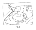
- FIG. 9 is a side perspective view of a motor mounted to a watercraft in accordance with one or more aspects of the present invention.
- watercraft 1 is configured as a boat having a bow 2 and a stern 3 .
- Watercraft 1 includes a hull 10 and a transom 11 , wherein the transom 11 defines a platform extending from the stern 3 of the watercraft.
- a deck 12 Extending forward of the transom 11 is a deck 12 also defining a platform surface.
- the deck 12 is slightly elevated above the surface of the transom 11 but need not necessarily be.
- Deck 12 generally defines the deck of the watercraft 1 extending forward toward the cockpit 4 of the watercraft 1 .
- Disposed at the rear of deck 12 adjacent to the transom 11 are a port engine enclosure 13 and a starboard engine enclosure 14 .
- the top of the enclosures 13 and 14 define seating surfaces 13 ′ and 14 ′, respectively.
- the enclosures 13 and 14 are separated by passage 15 which provides access between the cockpit 4 and transom 11 .
- cavities 16 and 18 are disposed through the deck 12 adjacent to the transom 11 and define a space to accommodate outboard motors 17 and 19 , respectively.
- cavities 16 and 18 are bored completely through deck 12 such that motors 17 and 19 are at least partially submerged in the water beneath the watercraft 1 .
- the front walls 20 and 21 of the cavities 16 and 18 provide a surface on which to mount the motors 17 and 19 , respectively. Accordingly, enclosures 13 and 14 provide a means to hide and enclose the motors 17 and 19 .
- the enclosures 13 and 14 are hingeably attached to the deck 12 by hinges 131 and 141 , respectively. In some embodiments, the enclosures 13 and 14 therefore hinge backward toward to the stern 3 of the watercraft 1 in order to expose the cavities 16 and 18 provide easy access to the motors 17 and 19 .
- FIG. 6 a top view of the configuration of the present invention is shown, with motor 17 mounted inside cavity 16 of deck 12 .
- the enclosures 13 and 14 are omitted to better depict the cavities 16 and 18 and the motors 17 and 19 .
- Further shown is the passage 15 disposed between the two motors/enclosures as well as the front wall 20 on which the motor 17 is mounted.
- FIGS. 7 and 8 depict an embodiment of the enclosure of the present invention, in this case port enclosure 13 , in isolation.
- enclosure 13 is generally a three sided member having a seating surface 13 ′.
- the enclosure 13 meets the port gunwale 30 of the watercraft 1 in order to fully enclose the cavity 16 at the stern of the watercraft 1 .
- enclosure 14 meets the starboard gunwale 31 of watercraft 1 in order to fully enclose cavity 18 at the stern of the watercraft 1 .
- the gunwales 30 and 31 delimit the outer boundary of their respective enclosure 13 and 14 .
- the gunwales 30 and 31 of the watercraft 1 define the lateral boundaries of the enclosures 13 and 14 , respectively, other configurations are possible.
- the enclosure may be four sided and therefore discrete from the gunwales of the watercraft 1 .
- the surface 13 ′ includes one or more latches 40 which are configured to removably engaged the front wall 20 in order to secure the enclosure 13 to the watercraft 1 during operation.
- the perimeter 43 of the enclosure 13 includes a gasket 44 that, when the enclosure 13 is closed, provides a tight seal to reduce noise from the motor while also limiting air leakage from the motor's operation zone to the outside environment.
- the gasket 44 comprises a rubber or rubber compound having a D-shaped cross-section. Other configurations of gaskets may be equally suitable.
- the interior of the enclosures 13 and 14 are configured for optimal motor operating conditions including providing enough interior space to allow for full articulation of the motors 17 and 19 according to manufacturers' specifications. Further, in some embodiments, the interior surfaces of the enclosures 13 and 14 comprise a glossy surface with provides for easier cleaning as well as to allow water to slake away more readily to prevent moisture accumulation inside the enclosure 13 and 14 , which could harm engine performance. Further, the enclosures 13 and 14 include curvature 42 (See FIG. 8 ) which promotes air turnover, thus ensuring cooler engine operating temperatures. The curvature 42 also promotes the dissipation of combustion gases inside the enclosure.
- the present invention further enhances motor performance, convenience, and safety by not pulling intake air from the interior of the enclosures 13 and 14 .
- the present invention provides a connection between the engine air intake manifold and the bilge area of the watercraft 1 , i.e. the space inside hull 10 of watercraft 1 .
- Plumbing is provided in the form of a conduit 90 that is connected between the intake 91 of the motor 17 and an aperture 92 disposed on the interior of the gunwale 30 of the watercraft 1 .
- the interior of the gunwale 30 is coextensive with the interior bilge area of the hull 10 .
- This configuration allows air to be drawn from the bilge area to the intake manifold 91 of the motor 17 which ultimately mitigates the temperature and moisture content of the intake air.
- a similar configuration is provided with respect to motor 14 on the starboard side of the watercraft 1 .
- the plumbing of air from the bilge area to the motor improves the overall quality of the intake air, improving performance as compared to allowing the motor to take air from the moister, warmer motor enclosure 13 and 14 area.
- enclosures 13 and 14 may comprise a variety of materials including fiberglass, plastics, resins, and combinations thereof. It is further appreciated that the size and overall shape of the enclosures 13 and 14 can vary depending on the size of the motor or motors selected to power a given watercraft 1 . It is understood, however, that the interior curvature 42 should be maintained for improved air turnover and expulsion of combustion gases.
- usable deck space at the stern of the vessel is greatly increased because the outboard motors are hidden and concealed by the enclosures 13 and 14 which provide seating surfaces 13 ′ and 14 ′. Further, deck space and usability is enhanced because there is unobstructed deck and transom surface area extending rearwardly past the motors. This is also a safer configuration for boaters who wish to access the stern of the vessel as the motors are not exposed to the boater. Further still, the boat operator maintains the benefits of outboard motors while enjoying a more streamlined and pleasing appearance of the watercraft.
Abstract
Description
Claims (7)
Priority Applications (1)
| Application Number | Priority Date | Filing Date | Title |
|---|---|---|---|
| US13/836,929 US9126664B1 (en) | 2013-03-15 | 2013-03-15 | Hidden outboard engine enclosures |
Applications Claiming Priority (1)
| Application Number | Priority Date | Filing Date | Title |
|---|---|---|---|
| US13/836,929 US9126664B1 (en) | 2013-03-15 | 2013-03-15 | Hidden outboard engine enclosures |
Publications (1)
| Publication Number | Publication Date |
|---|---|
| US9126664B1 true US9126664B1 (en) | 2015-09-08 |
Family
ID=54012447
Family Applications (1)
| Application Number | Title | Priority Date | Filing Date |
|---|---|---|---|
| US13/836,929 Active 2033-05-20 US9126664B1 (en) | 2013-03-15 | 2013-03-15 | Hidden outboard engine enclosures |
Country Status (1)
| Country | Link |
|---|---|
| US (1) | US9126664B1 (en) |
Cited By (9)
| Publication number | Priority date | Publication date | Assignee | Title |
|---|---|---|---|---|
| JP2017056757A (en) * | 2015-09-14 | 2017-03-23 | ヤマハ発動機株式会社 | Outboard engine boat |
| US10085566B1 (en) * | 2017-08-03 | 2018-10-02 | Brunswick Corporation | Marine vessels and modular deck and seating configurations for marine vessels |
| US10124859B2 (en) * | 2015-11-03 | 2018-11-13 | Yamaha Hatsudoki Kabushiki Kaisha | Watercraft |
| US11492088B1 (en) * | 2019-05-31 | 2022-11-08 | Brp Us Inc. | Boat having a hatch and a marine outboard engine with a bumper for abutting the hatch |
| US11498653B1 (en) | 2018-12-31 | 2022-11-15 | Brp Us Inc. | Marine engine assembly |
| US11505299B1 (en) | 2018-12-31 | 2022-11-22 | Brp Us Inc. | Marine engine assembly |
| WO2023187888A1 (en) * | 2022-03-28 | 2023-10-05 | 本田技研工業株式会社 | Ship |
| USD1003801S1 (en) | 2021-07-02 | 2023-11-07 | Brunswick Corporation | Bilge intake for marine vessel |
| US11945565B1 (en) | 2021-07-07 | 2024-04-02 | Brunswick Corporation | Marine vessels and methods of making marine vessels providing air flow for an engine compartment |
Citations (16)
| Publication number | Priority date | Publication date | Assignee | Title |
|---|---|---|---|---|
| US3144858A (en) | 1962-10-15 | 1964-08-18 | Inboard Marine Inc | Air-cooled inboard engine |
| US3371362A (en) * | 1966-01-24 | 1968-03-05 | Frank W. Butler | Adjustable outboard well |
| US3452704A (en) | 1966-07-14 | 1969-07-01 | Outboard Marine Corp | Engine mounted on a gimbal-like frame |
| US3702485A (en) * | 1970-12-07 | 1972-11-14 | Chris Craft Ind Inc | Outboard motorboat with inboard mount |
| US3790977A (en) * | 1972-01-24 | 1974-02-12 | Germain Bombardier | Hull construction for watercraft |
| US4996937A (en) | 1987-09-30 | 1991-03-05 | Kawasaki Jukogyo Kabushiki Kaisha | Small boat |
| US4997398A (en) | 1985-10-02 | 1991-03-05 | E. P. Barrus Limited | Internal combustion air intake |
| US5129847A (en) | 1984-07-16 | 1992-07-14 | Outboard Marine Corporation | Pivotal air induction for marine propulsion unit |
| US5176551A (en) | 1991-01-18 | 1993-01-05 | Outboard Marine Corporation | Arrangement for supplying combustion air to an outboard motor |
| US5409409A (en) | 1991-01-04 | 1995-04-25 | Outboard Marine Corporation | Marine apparatus |
| US5505644A (en) | 1995-01-18 | 1996-04-09 | Ray Industries, Inc. | Submerged marine exhaust system |
| US7056172B2 (en) | 2003-08-07 | 2006-06-06 | Bombardier Recreational Products Inc. | Engine cover with air intake system for watercraft |
| US7413492B2 (en) | 2006-04-10 | 2008-08-19 | Ab Volvo | Watercraft with engine housing |
| US20090224132A1 (en) | 2008-03-05 | 2009-09-10 | Yamaha Hatsudoki Kabushiki Kaisha | Boat body and boat including the same |
| WO2010116576A1 (en) | 2009-03-30 | 2010-10-14 | ヤマハ発動機株式会社 | Ship |
| US20120115376A1 (en) | 2010-11-09 | 2012-05-10 | Suzuki Motor Corporation | Engine case of outboard motor |
-
2013
- 2013-03-15 US US13/836,929 patent/US9126664B1/en active Active
Patent Citations (18)
| Publication number | Priority date | Publication date | Assignee | Title |
|---|---|---|---|---|
| US3144858A (en) | 1962-10-15 | 1964-08-18 | Inboard Marine Inc | Air-cooled inboard engine |
| US3371362A (en) * | 1966-01-24 | 1968-03-05 | Frank W. Butler | Adjustable outboard well |
| US3452704A (en) | 1966-07-14 | 1969-07-01 | Outboard Marine Corp | Engine mounted on a gimbal-like frame |
| US3702485A (en) * | 1970-12-07 | 1972-11-14 | Chris Craft Ind Inc | Outboard motorboat with inboard mount |
| US3790977A (en) * | 1972-01-24 | 1974-02-12 | Germain Bombardier | Hull construction for watercraft |
| US5129847A (en) | 1984-07-16 | 1992-07-14 | Outboard Marine Corporation | Pivotal air induction for marine propulsion unit |
| US4997398A (en) | 1985-10-02 | 1991-03-05 | E. P. Barrus Limited | Internal combustion air intake |
| US4996937A (en) | 1987-09-30 | 1991-03-05 | Kawasaki Jukogyo Kabushiki Kaisha | Small boat |
| US5562511A (en) | 1991-01-04 | 1996-10-08 | Outboard Marine Corporation | Marine apparatus |
| US5409409A (en) | 1991-01-04 | 1995-04-25 | Outboard Marine Corporation | Marine apparatus |
| US5176551A (en) | 1991-01-18 | 1993-01-05 | Outboard Marine Corporation | Arrangement for supplying combustion air to an outboard motor |
| US5505644A (en) | 1995-01-18 | 1996-04-09 | Ray Industries, Inc. | Submerged marine exhaust system |
| US7056172B2 (en) | 2003-08-07 | 2006-06-06 | Bombardier Recreational Products Inc. | Engine cover with air intake system for watercraft |
| US7413492B2 (en) | 2006-04-10 | 2008-08-19 | Ab Volvo | Watercraft with engine housing |
| US20090224132A1 (en) | 2008-03-05 | 2009-09-10 | Yamaha Hatsudoki Kabushiki Kaisha | Boat body and boat including the same |
| WO2010116576A1 (en) | 2009-03-30 | 2010-10-14 | ヤマハ発動機株式会社 | Ship |
| US20120028517A1 (en) | 2009-03-30 | 2012-02-02 | Yamaha Hatsudoki Kabushiki Kaisha | Marine vessel |
| US20120115376A1 (en) | 2010-11-09 | 2012-05-10 | Suzuki Motor Corporation | Engine case of outboard motor |
Cited By (10)
| Publication number | Priority date | Publication date | Assignee | Title |
|---|---|---|---|---|
| JP2017056757A (en) * | 2015-09-14 | 2017-03-23 | ヤマハ発動機株式会社 | Outboard engine boat |
| US10124859B2 (en) * | 2015-11-03 | 2018-11-13 | Yamaha Hatsudoki Kabushiki Kaisha | Watercraft |
| US10085566B1 (en) * | 2017-08-03 | 2018-10-02 | Brunswick Corporation | Marine vessels and modular deck and seating configurations for marine vessels |
| US11498653B1 (en) | 2018-12-31 | 2022-11-15 | Brp Us Inc. | Marine engine assembly |
| US11505299B1 (en) | 2018-12-31 | 2022-11-22 | Brp Us Inc. | Marine engine assembly |
| US11492088B1 (en) * | 2019-05-31 | 2022-11-08 | Brp Us Inc. | Boat having a hatch and a marine outboard engine with a bumper for abutting the hatch |
| US11767092B2 (en) | 2019-05-31 | 2023-09-26 | Brp Us Inc. | Marine outboard engine with a bumper for abutting the hatch |
| USD1003801S1 (en) | 2021-07-02 | 2023-11-07 | Brunswick Corporation | Bilge intake for marine vessel |
| US11945565B1 (en) | 2021-07-07 | 2024-04-02 | Brunswick Corporation | Marine vessels and methods of making marine vessels providing air flow for an engine compartment |
| WO2023187888A1 (en) * | 2022-03-28 | 2023-10-05 | 本田技研工業株式会社 | Ship |
Similar Documents
| Publication | Publication Date | Title |
|---|---|---|
| US9126664B1 (en) | Hidden outboard engine enclosures | |
| JP6141869B2 (en) | Ships with extensions for supporting swimming platforms and concealing outboard motors | |
| US7185599B1 (en) | Jet drive propulsion system for a pontoon boat | |
| US7182033B1 (en) | Self-contained marine propulsion system for a pontoon boat | |
| US9862470B2 (en) | Large outboard motor for marine vessel application and related methods of making and operating same | |
| US9108710B1 (en) | Pontoon boat | |
| US20060228959A1 (en) | Pontoon boat with jet propulsion drive | |
| US9809289B2 (en) | Hull mounted, steerable marine drive with trim actuation | |
| US4458622A (en) | Boat having a variable hull configuration | |
| US3347201A (en) | Power vessels | |
| US9216795B2 (en) | Hull design with engine air flow system | |
| US20080236471A1 (en) | Powered kayak-like boat | |
| GB2046689A (en) | Mechanically propelled boats | |
| US6468119B1 (en) | Composite stern drive assembly | |
| AU2014306895B2 (en) | A hull mounted, steerable marine drive with trim actuation | |
| US6279499B1 (en) | Rotational jet-drive bow thruster for a marine propulsion system | |
| US6468120B1 (en) | Single cylinder trim/tilt assembly | |
| US20070028824A1 (en) | Boat control system | |
| GB2554045A (en) | Boat auxiliary propulsion unit | |
| JP2001097277A (en) | Bottom structure of small ship | |
| US11167829B2 (en) | Staggered vessel transom for attachment of multiple engines | |
| US4940436A (en) | Marine drive system with inboard mounted engine and depending drive unit | |
| US11492088B1 (en) | Boat having a hatch and a marine outboard engine with a bumper for abutting the hatch | |
| US9079638B2 (en) | Storage system for a watercraft | |
| KR20090123459A (en) | Propelling system for boat |
Legal Events
| Date | Code | Title | Description |
|---|---|---|---|
| AS | Assignment |
Owner name: JPMORGAN CHASE BANK, N.A., AS ADMINISTRATIVE AGENT Free format text: SECURITY INTEREST;ASSIGNORS:BRUNSWICK CORPORATION;BRUNSWICK BOWLING & BILLIARDS CORP.;LEISERV, LLC;AND OTHERS;REEL/FRAME:033263/0281 Effective date: 20140626 |
|
| AS | Assignment |
Owner name: BOSTON WHALER, INC., ILLINOIS Free format text: RELEASE BY SECURED PARTY;ASSIGNOR:JPMORGAN CHASE BANK, N.A.;REEL/FRAME:034794/0257 Effective date: 20141224 Owner name: BRUNSWICK BOWLING & BILLIARDS CORPORATION, ILLINOI Free format text: RELEASE BY SECURED PARTY;ASSIGNOR:JPMORGAN CHASE BANK, N.A.;REEL/FRAME:034794/0257 Effective date: 20141224 Owner name: BRUNSWICK COMMERCIAL & GOVERNMENT PRODUCTS, INC., Free format text: RELEASE BY SECURED PARTY;ASSIGNOR:JPMORGAN CHASE BANK, N.A.;REEL/FRAME:034794/0257 Effective date: 20141224 Owner name: BRUNSWICK CORPORATION, ILLINOIS Free format text: RELEASE BY SECURED PARTY;ASSIGNOR:JPMORGAN CHASE BANK, N.A.;REEL/FRAME:034794/0257 Effective date: 20141224 Owner name: BRUNSWICK LEISURE BOAT COMPANY, LLC, ILLINOIS Free format text: RELEASE BY SECURED PARTY;ASSIGNOR:JPMORGAN CHASE BANK, N.A.;REEL/FRAME:034794/0257 Effective date: 20141224 Owner name: LUND BOAT COMPANY, ILLINOIS Free format text: RELEASE BY SECURED PARTY;ASSIGNOR:JPMORGAN CHASE BANK, N.A.;REEL/FRAME:034794/0257 Effective date: 20141224 |
|
| AS | Assignment |
Owner name: BRUNSWICK CORPORATION, ILLINOIS Free format text: ASSIGNMENT OF ASSIGNORS INTEREST;ASSIGNORS:DENSON, JOHN CLIFFORD;BUCACCIO, THOMAS;HERRINGTON, FREDERICK CHARLES;REEL/FRAME:035543/0990 Effective date: 20130624 |
|
| STCF | Information on status: patent grant |
Free format text: PATENTED CASE |
|
| MAFP | Maintenance fee payment |
Free format text: PAYMENT OF MAINTENANCE FEE, 4TH YEAR, LARGE ENTITY (ORIGINAL EVENT CODE: M1551); ENTITY STATUS OF PATENT OWNER: LARGE ENTITY Year of fee payment: 4 |
|
| MAFP | Maintenance fee payment |
Free format text: PAYMENT OF MAINTENANCE FEE, 8TH YEAR, LARGE ENTITY (ORIGINAL EVENT CODE: M1552); ENTITY STATUS OF PATENT OWNER: LARGE ENTITY Year of fee payment: 8 |