US5094360A - Screen basket - Google Patents
Screen basket Download PDFInfo
- Publication number
- US5094360A US5094360A US07/661,384 US66138491A US5094360A US 5094360 A US5094360 A US 5094360A US 66138491 A US66138491 A US 66138491A US 5094360 A US5094360 A US 5094360A
- Authority
- US
- United States
- Prior art keywords
- screen
- rods
- recesses
- rings
- basket
- Prior art date
- Legal status (The legal status is an assumption and is not a legal conclusion. Google has not performed a legal analysis and makes no representation as to the accuracy of the status listed.)
- Expired - Lifetime
Links
- 229910000831 Steel Inorganic materials 0.000 claims description 14
- 239000010959 steel Substances 0.000 claims description 14
- 238000004519 manufacturing process Methods 0.000 claims description 11
- 230000007704 transition Effects 0.000 claims description 11
- 238000000034 method Methods 0.000 claims description 10
- 238000005452 bending Methods 0.000 claims description 6
- 238000003780 insertion Methods 0.000 claims description 6
- 230000037431 insertion Effects 0.000 claims description 6
- 238000003466 welding Methods 0.000 claims description 6
- 230000007423 decrease Effects 0.000 claims description 4
- 238000003754 machining Methods 0.000 claims description 4
- 230000002093 peripheral effect Effects 0.000 claims description 4
- 230000000717 retained effect Effects 0.000 claims description 4
- 239000000463 material Substances 0.000 description 5
- 238000012216 screening Methods 0.000 description 4
- 238000013461 design Methods 0.000 description 3
- 230000006978 adaptation Effects 0.000 description 1
- 238000013459 approach Methods 0.000 description 1
- 230000006378 damage Effects 0.000 description 1
- 238000005516 engineering process Methods 0.000 description 1
- 238000001125 extrusion Methods 0.000 description 1
- 230000002349 favourable effect Effects 0.000 description 1
- 238000003698 laser cutting Methods 0.000 description 1
- 238000003825 pressing Methods 0.000 description 1
- 230000002787 reinforcement Effects 0.000 description 1
Images


Classifications
-
- B—PERFORMING OPERATIONS; TRANSPORTING
- B07—SEPARATING SOLIDS FROM SOLIDS; SORTING
- B07B—SEPARATING SOLIDS FROM SOLIDS BY SIEVING, SCREENING, SIFTING OR BY USING GAS CURRENTS; SEPARATING BY OTHER DRY METHODS APPLICABLE TO BULK MATERIAL, e.g. LOOSE ARTICLES FIT TO BE HANDLED LIKE BULK MATERIAL
- B07B1/00—Sieving, screening, sifting, or sorting solid materials using networks, gratings, grids, or the like
- B07B1/46—Constructional details of screens in general; Cleaning or heating of screens
- B07B1/4609—Constructional details of screens in general; Cleaning or heating of screens constructional details of screening surfaces or meshes
- B07B1/4618—Manufacturing of screening surfaces
-
- B—PERFORMING OPERATIONS; TRANSPORTING
- B01—PHYSICAL OR CHEMICAL PROCESSES OR APPARATUS IN GENERAL
- B01D—SEPARATION
- B01D29/00—Filters with filtering elements stationary during filtration, e.g. pressure or suction filters, not covered by groups B01D24/00 - B01D27/00; Filtering elements therefor
- B01D29/11—Filters with filtering elements stationary during filtration, e.g. pressure or suction filters, not covered by groups B01D24/00 - B01D27/00; Filtering elements therefor with bag, cage, hose, tube, sleeve or like filtering elements
- B01D29/13—Supported filter elements
-
- B—PERFORMING OPERATIONS; TRANSPORTING
- B01—PHYSICAL OR CHEMICAL PROCESSES OR APPARATUS IN GENERAL
- B01D—SEPARATION
- B01D29/00—Filters with filtering elements stationary during filtration, e.g. pressure or suction filters, not covered by groups B01D24/00 - B01D27/00; Filtering elements therefor
- B01D29/44—Edge filtering elements, i.e. using contiguous impervious surfaces
- B01D29/445—Bar screens
-
- B—PERFORMING OPERATIONS; TRANSPORTING
- B07—SEPARATING SOLIDS FROM SOLIDS; SORTING
- B07B—SEPARATING SOLIDS FROM SOLIDS BY SIEVING, SCREENING, SIFTING OR BY USING GAS CURRENTS; SEPARATING BY OTHER DRY METHODS APPLICABLE TO BULK MATERIAL, e.g. LOOSE ARTICLES FIT TO BE HANDLED LIKE BULK MATERIAL
- B07B1/00—Sieving, screening, sifting, or sorting solid materials using networks, gratings, grids, or the like
- B07B1/12—Apparatus having only parallel elements
-
- B—PERFORMING OPERATIONS; TRANSPORTING
- B07—SEPARATING SOLIDS FROM SOLIDS; SORTING
- B07B—SEPARATING SOLIDS FROM SOLIDS BY SIEVING, SCREENING, SIFTING OR BY USING GAS CURRENTS; SEPARATING BY OTHER DRY METHODS APPLICABLE TO BULK MATERIAL, e.g. LOOSE ARTICLES FIT TO BE HANDLED LIKE BULK MATERIAL
- B07B1/00—Sieving, screening, sifting, or sorting solid materials using networks, gratings, grids, or the like
- B07B1/18—Drum screens
-
- B—PERFORMING OPERATIONS; TRANSPORTING
- B07—SEPARATING SOLIDS FROM SOLIDS; SORTING
- B07B—SEPARATING SOLIDS FROM SOLIDS BY SIEVING, SCREENING, SIFTING OR BY USING GAS CURRENTS; SEPARATING BY OTHER DRY METHODS APPLICABLE TO BULK MATERIAL, e.g. LOOSE ARTICLES FIT TO BE HANDLED LIKE BULK MATERIAL
- B07B1/00—Sieving, screening, sifting, or sorting solid materials using networks, gratings, grids, or the like
- B07B1/46—Constructional details of screens in general; Cleaning or heating of screens
- B07B1/4609—Constructional details of screens in general; Cleaning or heating of screens constructional details of screening surfaces or meshes
- B07B1/4681—Meshes of intersecting, non-woven, elements
-
- D—TEXTILES; PAPER
- D21—PAPER-MAKING; PRODUCTION OF CELLULOSE
- D21D—TREATMENT OF THE MATERIALS BEFORE PASSING TO THE PAPER-MAKING MACHINE
- D21D5/00—Purification of the pulp suspension by mechanical means; Apparatus therefor
- D21D5/02—Straining or screening the pulp
- D21D5/16—Cylinders and plates for screens
-
- Y—GENERAL TAGGING OF NEW TECHNOLOGICAL DEVELOPMENTS; GENERAL TAGGING OF CROSS-SECTIONAL TECHNOLOGIES SPANNING OVER SEVERAL SECTIONS OF THE IPC; TECHNICAL SUBJECTS COVERED BY FORMER USPC CROSS-REFERENCE ART COLLECTIONS [XRACs] AND DIGESTS
- Y10—TECHNICAL SUBJECTS COVERED BY FORMER USPC
- Y10T—TECHNICAL SUBJECTS COVERED BY FORMER US CLASSIFICATION
- Y10T29/00—Metal working
- Y10T29/49—Method of mechanical manufacture
- Y10T29/496—Multiperforated metal article making
- Y10T29/49604—Filter
Definitions
- the invention concerns rotationally symmetric screen baskets featuring axially parallel bars with screen slots contained in between, and featuring rings that are coaxial to the basket axis for support of the bars, where the rings are provided with recesses open toward the rim of the rings, and the feet of the bars are placed in the recesses and fastened.
- Such screen baskets and processes for making them are known from the German patent disclosure 33 27 422.
- the attachment of the bars to the rings may be very expensive to manufacture.
- the bars are generally fastened on the rings by welding. This involves several dissatis: the welding sets up stresses in the material causing a warping of the entire screen basket; the fastening is not sufficiently safe, since the welding seams may split in the course of time; the fabrication is unwieldy and time-consuming; and, it is relatively difficult to accurately adjust the width of the screen slot between two adjacent bars.
- the problem underlying the invention is to provide a screen basket which is not associated with the said disadvantages, and to provide screen baskets whose manufacture is correspondingly more favorable.
- this is to be accomplished by avoiding the said welding stresses, in that the fastening is marked by greater safety, the screen slots can be adjusted more accurately, and the manufacture becomes simpler and more cost-efficient.
- the screen basket is of the type having axially parallel bars with screen slots therebetween.
- the basket further has an axis and includes rings for support of the bars.
- the rings are coaxial to the basket axis, have an inner rim, and are provided with recesses which open toward the rim.
- the bars may be provided with feet whereby the feet are positioned and fastened in said recesses.
- the invention comprises a screen basket wherein a plurality of screen rods having screen slots therebetween is provided.
- the screen rods extend generally along a cylinder circumference surface of the basket and are axially parallel to the center axis of the basket.
- Each of the screen rods has a radially outer foot part and has a head part projecting radially inwardly from the foot part.
- Each of the head parts includes a transition part at the juncture wherein the head part is joined to the foot part.
- the head parts further have respective side surfaces which are tilted between about 7 degrees to about 18 degrees relative to the respective radial of the screen basket.
- the head parts have respective cross sectional dimensions whereby the cross sectional dimensions increase in the radially inward direction.
- the transition parts and the foot parts have respective cross sectional dimensions in circumferential direction wherein the cross sectional dimension of each of the transition parts is at least 0.6 mm less than the maximum cross sectional dimension of the foot parts.
- a plurality of retaining rings supporting the bars is also provided.
- the rings have an inner rim and extend circumferentially around the cylinder circumference surface.
- the rings are mutually spaced and generally coaxial to the axis.
- the rings are provided with recesses which open toward the rim.
- the foot parts are positioned in the recesses.
- the present invention in accordance with another embodiment, comprises a screen basket wherein a plurality of screen rods having screen slots therebetween is provided.
- the screen rods extend generally along a cylinder circumference surface of the basket and are axially parallel to the center axis of the basket.
- a plurality of retaining rings extending along the cylinder circumference surface for supporting said screen rods is provided.
- the rings are formed from bodies whereby the bodies are rounded into rings.
- the rings are coaxial to the axis and are spaced generally equidistant from each other along the axis.
- the rings further have an inner rim and are provided with recesses which open toward the rim.
- the screen rods are adapted to be placed in the recesses prior to the rounding of the rings so that the rods are clamped into position in the recesses.
- Each of the screen rods has side surfaces which in relation to the radial center line of the cross sections of the screen rod are tilted such that the cross section decreases generally in a uniform manner from radially inside to radially outside.
- the side surfaces may include either recesses or projections on one or both sides of said radial center line.
- the present invention in accordance with yet another embodiment, comprises a process for the manufacture of a rotationally symmetric screen basket having axially parallel screen rods aligned so that screen slots are defined therebetween.
- the screen basket further has an axis, and includes rings for support of the screen rods, said rings being coaxial with the axis.
- Each of the rings has an inner rim, and is provided with a recess which opens toward said rim.
- the screen rods are positioned and fastened in said recesses.
- the process comprises the following steps: 1) providing substantially elongated retaining rods to be rounded into the rings, said retaining rods having said recesses formed therein; 2) placing the screen rods into the recesses prior to rounding the retaining rods into rings, said screen rods being placed in said recesses by inserting them into the recesses in transverse direction with respect to the retaining rods, one after the other, by plugging them into the recesses of all the rods so that the screen rods are retained in said recesses as a catchlock; 3) rounding the retaining rods into rings so that the recesses are narrowed, whereby the screen rods are clamped therein; and 4) welding the ends of the rings to one another.
- the present invention in accordance with yet another embodiment, comprises a generally "flat" (planar or arcuate) screen.
- the screen has a plurality of screen rods positioned in spaced parallelism so that screen slots are defined therebetween.
- a plurality of retaining bars are provided for supporting the screen rods.
- Each of the retaining bars has a plurality of recesses formed therein.
- the retaining bars are positioned in spaced parallelism, generally equidistant along the screen.
- the screen rods are clamped in the recesses in transverse direction of the retaining bars, whereby the screen is formed.
- the screen of this embodiment may be planar, or generally arcuate in shape.
- the present invention in accordance with a further embodiment, comprises a method for the manufacture of a planar or generally arcuate screen.
- the method comprises the following steps: providing a plurality of substantially elongated retaining rods having an inner surface and an outer surface, wherein each of the rods has a plurality of recesses formed along the inner surface; providing a plurality of screen rods for insertion into the recesses; aligning the retaining rods in spaced parallelism whereby the recesses are likewise aligned in spaced parallelism; bending the retaining rods in a direction opposite to the recesses so that the recesses are enlarged; inserting the retaining rods into the enlarged recesses by way of a transverse snap-in operation; and relieving the bending of the retaining rods whereby the screen rods are clamped in the recesses so that a screen is formed.
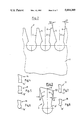
- FIG. 1 illustrates a perspective view of a section of a screen basket according to the present invention
- FIG. 2 illustrates a steel rod provided with recesses
- FIG. 3 illustrates a screen rod for insertion into a recess in the steel rod
- FIGS. 4-8 illustrate alternate configurations of the screen rod shown in FIG. 3;
- FIG. 9 illustrates a strainer basket according to an embodiment of the present invention showing coaxially aligned supporting rings 1', and showing reinforcement rods 38 that tend parallel to the screen rods;
- FIGS. 10-18 illustrate further embodiments of the present invention showing alternative configurations of the bars and recesses
- FIG. 19 illustrates another embodiment of the present invention, showing a screen having generally arcuate retaining bars.
- FIG. 1 details a section of a retaining ring 1' for a screen basket.
- Retaining ring 1' features recesses 2' made, for example, by a wire type electrodischarge machining.
- profile bars, or screen rods, 3 which are slipped into the various recesses 2' in such a way that, when viewed in plan view, they will extend perpendicular to the ring section 1' and be situated parallel to one another. This leaves between adjacent bars 3 a space 4 which forms the screen slot.
- the ring section 1' represents part of a continuous ring which on its entire inner circumference features bars, or rods, 3 of the illustrated type.
- the ring section illustrated in FIG. 2 is shown in an early stage of its fabrication, namely that of a steel rod 1 that has not yet been rounded into a ring. However, the recesses 2 have already been completed, but not yet slightly deformed into recesses 2' of ring 1'.
- the side faces 5 and 6 of the recesses extend at specific angles--here ⁇ and ⁇ --to the vertical.
- Line “V" in FIG. 2 represents a center plane, or center axis of the profile cross section, of the screen rod.
- Electrodischarge machining can now be performed on the entire packet, i.e., on a number of steel ross, in a single operation.
- the recesses in the retaining rods may also be accomplished by, for example, laser cutting.
- the screen rod (profile bar) 3 illustrated in FIG. 3 is made, e.g., by an extrusion or drawing process. Its design is such that at any rate it can be inserted in the recess 2 in the steel rod 1 without difficulty, as long as the steel rod 1 has not been rounded yet to its final shape. As can be seen in this embodiment, the foot part 3' of the screen rod 3 is circular in cross section. FIGS. 4-8 show alternative configurations of the screen rod in cross section.
- the utmost part of the head part of screen rods 3, 14-18 that is, the part which protrudes out of the recess in the steel rod 1, sticks in the finished condition of the screen basket radially inward with respect to retaining ring 1' into the screen basket center and is of a design such as will be optimal for the technology of the dewatering or sorting.
- the side surfaces 7, 8 of the head part form with the vertical a specific angle of inclination, presently the angles ⁇ and ⁇ .
- the cross-section of head parts 3, 14-18, respectively, substantially widens in this radially inward direction.
- the width, in circumferential direction or lengthwise of the rods 1, of the portion of the head parts adjoining the foot part is at least 0.6 mm less than the maximum width, in said direction, of the foot part.
- the side planes of the head part of screen rod 3 generally taper at angles of between approximately 7 to 18 degrees each, or by 14 to 35 degrees if only one side of the screen rod, is oblique (i.e. side 8' in FIG. 11).
- a preferred embodiment of the invention is based on the clamping of the screen rods 3 in the recesses 2, as a consequence of rounding the steel rods 1 until reaching a circular shape, so that the steel rods 1 finally will have the shape of continuous rings.
- the side faces 5, 6 of the electrodischarge machined recesses 2 approach each other, thereby pressing down on the corresponding side faces 7, 8 of the screen rods 3 and clamping them in place.
- the said angles i.e., ⁇ and ⁇ on the side and ⁇ and ⁇ on the other, must be adapted to one another appropriately.
- the head part of the individual screen rod 3 that protrudes out of the recess 2 must in its condition of insertion in the recess 2 be somewhat slimmer than the funnel-shaped recess 2. How great the differences between the said angles will be, however, depends on various other circumstances, among others upon the selection of material. With appropriate materials selected for the screen rods 3 or the steel rods 1, the conditions may be highly variable. In the extreme case, for instance when selecting rubber or rubbery materials for the screen rods 3, it is even conceivable that the angles of the side faces 5 and 6 to the horizontal and the angles of the side faces 7 and 8 to the horizontal will be equally large.
- the dimension in cross section of the foot, or root, portion 3', 14', 15', etc., of the screen rod 3, 14, 15, etc., in the longitudinal direction of the clamping rods deviates only by at most 7/100 mm from the corresponding dimension of the cross section of the grooves of the clamping rods so that a slight gap exists therebetween in the initial state, that is, prior to forming the rod into a ring.
- the dimension in the transverse direction deviates only by at most 2/100 mm from the corresponding dimension of the cross section of the grooves of the clamping rods so that a slight gap also exists therebetween in the initial state, prior to forming the rod into a ring.
- the bars are pushed lengthwise into the grooves, with the grooves acting as clamping recesses with respect to the foot portions of the profile bars in the initial state prior to forming the rods into rings.
- the maximum dimension of the grooves in the lengthwise direction of the clamping rods is 2/1000th of the inner circumference of the rings.
- the dimension of the cross section of the screen rods 3, 14, 15, etc., at their radially inner portions in the longitudinal direction of the clamping rods, is relatively smaller than at the radially outer foot (root) portion 3', 14', 15', etc., in order to obtain a greater gap at the radially inner portion than at the radially outer portion in the initial state, prior to forming the rod into a ring.
- the maximal dimension of the cross section of the foot portion of the screen rods 3, 14, 15, etc., in the longitudinal direction of the rods is, by at least 0.6 mm, greater than the dimension of the cross section of the head part adjacent the foot portion.
- the cross section of the foot portion may also, for example, be substantially circular, rectangular, quadratic, elliptical or polygonal. Additional configurations are shown in FIGS. 10-17, such as the hook fashioned foot part shown in FIG. 10.
- screen rods 22 have respective foot parts 23 which extend sideways in hook fashion in relation to respective head parts 24.
- the cross section of the screen rods 3 is maximally 18 mm 2 .
- the cross section of the recesses 2' is maximally 16.5 mm 2 .
- the largest dimension of the screen rods 3 in the peripheral direction is preferably 3.8 mm.
- the recesses 2' in which the screen rods 3 are clamped in place feature in the clamping area, across at least 70% of the length of their cross sectional rim, the same cross section as the screen rods 3.
- the clamping rings are substantially straight rods having the grooves formed therein.
- the screen rods are inserted into the grooves so that a screen mat is produced.
- the ends of the screen mat are then brought together, rounding the screen mat.
- the ends of the screen mat are then welded to one another.
- the rods are formed into a ring, thereby forming a screening basket consisting of screening bars and clamping rings, forming a rigid screen structure.
- Centering rings may then be shrink-fitted to the end faces of the screen basket.
- the manufacture of the rings not be based on steel rods, but rather on other bodies that are already prerounded. It is only important that the rings are not yet completely rounded prior to insertion of the bars, that is, that they not yet form continuous rings.
- the head part of the screen rods 3 features recesses 35, 35' in its side surfaces that are essentially straight and extend slanted to the radial center line of the screen rods. There are no corresponding bearing surfaces in the recesses 2, 2' of the bars 1 or of the holder or support rings 1' to these side surfaces, so that in that area no clamping will take place.
- the side surfaces 7', 8' of the head parts may be tilted at the same angles ( ⁇ and ⁇ ) relative to the radial centerline of the screen rod cross sections, the same as similar side surfaces 27, 28 of the foot parts (FIG. 14).
- the screen rods have side surfaces which in relation of the radial center line of their cross section are tilted in such a way that the cross section decreases essentially uniformly from radially inside to radially outside.
- These side faces feature either recesses or projections on one or both sides to the said radial center line (FIGS. 13, 15 and 16).
- the projections 36, 36' in FIG. 13, or recesses such as 41, 42 in FIG. 15, of the screen rods serve to hold them in the rods 1 in the clamping process of the screen rods.
- at least 70% of the periphery of the cross section of the recesses of the rings 1' corresponds exactly to the cross section of the screen bars 3 in the corresponding (clamping) area.
- the screen rods 3 may be inserted into the recesses 2, 2', etc., by plugging them into the recesses in a direction transverse to the retaining rings. The screen rods are then retained in the recesses in the manner of a catchlock, one after the other.
- This embodiment may be best visualized by the embodiment shown in FIG. 16.
- a protrusion 41' extending from the recess of the retaining rod snaps into a corresponding recess 41" of the screen rod.
- Recess 41" of the screen rod should preferably have a dimension in the longitudinal direction of retaining rod 1 of only about 0.3 to 0.5 mm so that the individual "tooth" of the rods, which is formed between two recesses of them, is not too much deformed when the screen rod is plugged in.
- the embodiment shown in FIG. 16 is preferred for this plug-in operation, however two protrusions (or recesses, respectively) one on each side of the screen rods, may similarly be utilized as shown in FIGS. 13-15.
- two protrusions (recesses) may be too bulky for an easy plug-in operation in certain applications when compared to the embodiment shown in FIG. 16, the latter embodiment is generally preferred.
- the embodiments of FIGS. 13-15 are also generally suited for the purposes of the present invention.
- the protrusion 41' of the retaining rod 1, and the recesses 41" in the screen rod only partially match, which fact is maintained after bending the rods into rings.
- the matching area is so selected that the screen rod is retained in the recess of the retaining rod in the exact radial position until completion of the screen basket.
- the cross section of the recess 33 does not match with the cross section of the bar 30, likewise at the bottom line 34.
- FIGS. 13-16 All of the embodiments shown in FIGS. 13-16 are also suited for forming a "flat" screen, that may be planar or have a generally arcuate shape. An embodiment showing the arcuate shape is shown in FIG. 19.
- the embodiments having a "flat" screen may also operate by a plug-in or snap-fit of the screen rod into the retaining rod.
- the cross section of the screen rods need not be slimmer than the recesses of the retaining rods.
- the cross sections and all dimensions specified hereinbefore of the screen rods may be much larger in this embodiment, and the cross sectional dimensions of the recesses may be 2/100-1/10 mm smaller than those of the screen rods in the clamping area. Clearances may be equal to, or much larger, than with a screen basket.
- FIG. 18 is most appropriate for snap-in operation with flat screens (planar), showing recesses 52 on one side of the screen rods 51, in "reverse" configuration with respect to FIGS. 15 and 16, and with a gap 53 at the innermost part of the bars with respect to the retaining rods 145.
Landscapes
- Engineering & Computer Science (AREA)
- Chemical & Material Sciences (AREA)
- Chemical Kinetics & Catalysis (AREA)
- Mechanical Engineering (AREA)
- Manufacturing & Machinery (AREA)
- Combined Means For Separation Of Solids (AREA)
- Paper (AREA)
- Wire Processing (AREA)
- Filtering Materials (AREA)
- Electroluminescent Light Sources (AREA)
- Preparation Of Compounds By Using Micro-Organisms (AREA)
- Transition And Organic Metals Composition Catalysts For Addition Polymerization (AREA)
- Silicon Compounds (AREA)
Abstract
The invention concerns screen baskets featuring axially parallel screen rods with screen slots contained in between and, for support of the screen rods, rings that are coaxial with the basket axis, the rings being provided with recesses that are open toward the rim. The screen rods may have feet that are placed and fastened in the recesses. The screen rods are placed in the recesses while the rings do not have their final rounded shape. The rings are rounded so as to close the circular shape and to clamp the screen rods in place in the recesses that are constricted by the rounding.
Description
This application is a Continuation-In-Part of application Ser. No. 07/607,600 filed Oct. 31, 1990 still pending which is a continuation of application Ser. No. 07/570,392, filed Aug. 21, 1990 now abandoned.
The invention concerns rotationally symmetric screen baskets featuring axially parallel bars with screen slots contained in between, and featuring rings that are coaxial to the basket axis for support of the bars, where the rings are provided with recesses open toward the rim of the rings, and the feet of the bars are placed in the recesses and fastened. Such screen baskets and processes for making them are known from the German patent disclosure 33 27 422.
The attachment of the bars to the rings may be very expensive to manufacture. The bars are generally fastened on the rings by welding. This involves several disavantages: the welding sets up stresses in the material causing a warping of the entire screen basket; the fastening is not sufficiently safe, since the welding seams may split in the course of time; the fabrication is unwieldy and time-consuming; and, it is relatively difficult to accurately adjust the width of the screen slot between two adjacent bars.
The problem underlying the invention is to provide a screen basket which is not associated with the said disadvantages, and to provide screen baskets whose manufacture is correspondingly more favorable. In detail, this is to be accomplished by avoiding the said welding stresses, in that the fastening is marked by greater safety, the screen slots can be adjusted more accurately, and the manufacture becomes simpler and more cost-efficient.
This problem is solved by the features of the present invention. The screen basket is of the type having axially parallel bars with screen slots therebetween. The basket further has an axis and includes rings for support of the bars. The rings are coaxial to the basket axis, have an inner rim, and are provided with recesses which open toward the rim. The bars may be provided with feet whereby the feet are positioned and fastened in said recesses.
In one embodiment, the invention comprises a screen basket wherein a plurality of screen rods having screen slots therebetween is provided. The screen rods extend generally along a cylinder circumference surface of the basket and are axially parallel to the center axis of the basket. Each of the screen rods has a radially outer foot part and has a head part projecting radially inwardly from the foot part. Each of the head parts includes a transition part at the juncture wherein the head part is joined to the foot part. The head parts further have respective side surfaces which are tilted between about 7 degrees to about 18 degrees relative to the respective radial of the screen basket. The head parts have respective cross sectional dimensions whereby the cross sectional dimensions increase in the radially inward direction. The transition parts and the foot parts have respective cross sectional dimensions in circumferential direction wherein the cross sectional dimension of each of the transition parts is at least 0.6 mm less than the maximum cross sectional dimension of the foot parts. A plurality of retaining rings supporting the bars is also provided. The rings have an inner rim and extend circumferentially around the cylinder circumference surface. The rings are mutually spaced and generally coaxial to the axis. The rings are provided with recesses which open toward the rim. The foot parts are positioned in the recesses.
The present invention, in accordance with another embodiment comprises a screen basket wherein a plurality of screen rods having screen slots therebetween is provided. The screen rods extend generally along a cylinder circumference surface of the basket and are axially parallel to the center axis of the basket. A plurality of retaining rings extending along the cylinder circumference surface for supporting said screen rods is provided. The rings are formed from bodies whereby the bodies are rounded into rings. The rings are coaxial to the axis and are spaced generally equidistant from each other along the axis. The rings further have an inner rim and are provided with recesses which open toward the rim. The screen rods are adapted to be placed in the recesses prior to the rounding of the rings so that the rods are clamped into position in the recesses. Each of the screen rods has side surfaces which in relation to the radial center line of the cross sections of the screen rod are tilted such that the cross section decreases generally in a uniform manner from radially inside to radially outside. The side surfaces may include either recesses or projections on one or both sides of said radial center line.
The present invention, in accordance with yet another embodiment, comprises a process for the manufacture of a rotationally symmetric screen basket having axially parallel screen rods aligned so that screen slots are defined therebetween. The screen basket further has an axis, and includes rings for support of the screen rods, said rings being coaxial with the axis. Each of the rings has an inner rim, and is provided with a recess which opens toward said rim. The screen rods are positioned and fastened in said recesses. In particular, the process comprises the following steps: 1) providing substantially elongated retaining rods to be rounded into the rings, said retaining rods having said recesses formed therein; 2) placing the screen rods into the recesses prior to rounding the retaining rods into rings, said screen rods being placed in said recesses by inserting them into the recesses in transverse direction with respect to the retaining rods, one after the other, by plugging them into the recesses of all the rods so that the screen rods are retained in said recesses as a catchlock; 3) rounding the retaining rods into rings so that the recesses are narrowed, whereby the screen rods are clamped therein; and 4) welding the ends of the rings to one another.
The present invention, in accordance with yet another embodiment, comprises a generally "flat" (planar or arcuate) screen. The screen has a plurality of screen rods positioned in spaced parallelism so that screen slots are defined therebetween. A plurality of retaining bars are provided for supporting the screen rods. Each of the retaining bars has a plurality of recesses formed therein. The retaining bars are positioned in spaced parallelism, generally equidistant along the screen. The screen rods are clamped in the recesses in transverse direction of the retaining bars, whereby the screen is formed. The screen of this embodiment may be planar, or generally arcuate in shape.
The present invention, in accordance with a further embodiment, comprises a method for the manufacture of a planar or generally arcuate screen. The method comprises the following steps: providing a plurality of substantially elongated retaining rods having an inner surface and an outer surface, wherein each of the rods has a plurality of recesses formed along the inner surface; providing a plurality of screen rods for insertion into the recesses; aligning the retaining rods in spaced parallelism whereby the recesses are likewise aligned in spaced parallelism; bending the retaining rods in a direction opposite to the recesses so that the recesses are enlarged; inserting the retaining rods into the enlarged recesses by way of a transverse snap-in operation; and relieving the bending of the retaining rods whereby the screen rods are clamped in the recesses so that a screen is formed.
The above mentioned and other features and objects of this invention, and the manner of attaining them, will become more apparent and the invention itself will be better understood by reference to the following description of embodiments of the invention taken in conjunction with the accompanying drawings, wherein:
FIG. 1 illustrates a perspective view of a section of a screen basket according to the present invention;
FIG. 2 illustrates a steel rod provided with recesses;
FIG. 3 illustrates a screen rod for insertion into a recess in the steel rod;
FIGS. 4-8 illustrate alternate configurations of the screen rod shown in FIG. 3;
FIG. 9 illustrates a strainer basket according to an embodiment of the present invention showing coaxially aligned supporting rings 1', and showing reinforcement rods 38 that tend parallel to the screen rods;
FIGS. 10-18 illustrate further embodiments of the present invention showing alternative configurations of the bars and recesses;
FIG. 19 illustrates another embodiment of the present invention, showing a screen having generally arcuate retaining bars.
Corresponding reference characters indicate corresponding parts throughout the several views. The exemplification set out herein illustrates one preferred embodiment of the invention, in one form, and such exemplifications are not to be construed as limiting the scope of the invention in any manner.
FIG. 1 details a section of a retaining ring 1' for a screen basket. Retaining ring 1' features recesses 2' made, for example, by a wire type electrodischarge machining. Also depicted are profile bars, or screen rods, 3 which are slipped into the various recesses 2' in such a way that, when viewed in plan view, they will extend perpendicular to the ring section 1' and be situated parallel to one another. This leaves between adjacent bars 3 a space 4 which forms the screen slot.
As can be seen from the embodiment shown in FIG. 1, the ring section 1' represents part of a continuous ring which on its entire inner circumference features bars, or rods, 3 of the illustrated type.
The ring section illustrated in FIG. 2 is shown in an early stage of its fabrication, namely that of a steel rod 1 that has not yet been rounded into a ring. However, the recesses 2 have already been completed, but not yet slightly deformed into recesses 2' of ring 1'. The side faces 5 and 6 of the recesses extend at specific angles--here α and β--to the vertical. Line "V" in FIG. 2 represents a center plane, or center axis of the profile cross section, of the screen rod. For economy of manufacture, several steel rods 1 are placed parallel and in contact with one another prior to electrodischarge machining, so that they will form a packet. Electrodischarge machining can now be performed on the entire packet, i.e., on a number of steel ross, in a single operation. The recesses in the retaining rods may also be accomplished by, for example, laser cutting.
The screen rod (profile bar) 3 illustrated in FIG. 3 is made, e.g., by an extrusion or drawing process. Its design is such that at any rate it can be inserted in the recess 2 in the steel rod 1 without difficulty, as long as the steel rod 1 has not been rounded yet to its final shape. As can be seen in this embodiment, the foot part 3' of the screen rod 3 is circular in cross section. FIGS. 4-8 show alternative configurations of the screen rod in cross section. The utmost part of the head part of screen rods 3, 14-18, that is, the part which protrudes out of the recess in the steel rod 1, sticks in the finished condition of the screen basket radially inward with respect to retaining ring 1' into the screen basket center and is of a design such as will be optimal for the technology of the dewatering or sorting.
Here, too, it is evident again that the side surfaces 7, 8 of the head part form with the vertical a specific angle of inclination, presently the angles γ and δ. The cross-section of head parts 3, 14-18, respectively, substantially widens in this radially inward direction. The width, in circumferential direction or lengthwise of the rods 1, of the portion of the head parts adjoining the foot part is at least 0.6 mm less than the maximum width, in said direction, of the foot part. The side planes of the head part of screen rod 3 generally taper at angles of between approximately 7 to 18 degrees each, or by 14 to 35 degrees if only one side of the screen rod, is oblique (i.e. side 8' in FIG. 11).
As explained above, a preferred embodiment of the invention is based on the clamping of the screen rods 3 in the recesses 2, as a consequence of rounding the steel rods 1 until reaching a circular shape, so that the steel rods 1 finally will have the shape of continuous rings. In such rounding, the side faces 5, 6 of the electrodischarge machined recesses 2 approach each other, thereby pressing down on the corresponding side faces 7, 8 of the screen rods 3 and clamping them in place. Naturally, attention must be paid to not perform the clamping in excess, with the result of material destruction. Consequently, the said angles, i.e., α and β on the side and γ and δ on the other, must be adapted to one another appropriately. This means that the head part of the individual screen rod 3 that protrudes out of the recess 2 must in its condition of insertion in the recess 2 be somewhat slimmer than the funnel-shaped recess 2. How great the differences between the said angles will be, however, depends on various other circumstances, among others upon the selection of material. With appropriate materials selected for the screen rods 3 or the steel rods 1, the conditions may be highly variable. In the extreme case, for instance when selecting rubber or rubbery materials for the screen rods 3, it is even conceivable that the angles of the side faces 5 and 6 to the horizontal and the angles of the side faces 7 and 8 to the horizontal will be equally large.
The dimension in cross section of the foot, or root, portion 3', 14', 15', etc., of the screen rod 3, 14, 15, etc., in the longitudinal direction of the clamping rods deviates only by at most 7/100 mm from the corresponding dimension of the cross section of the grooves of the clamping rods so that a slight gap exists therebetween in the initial state, that is, prior to forming the rod into a ring. The dimension in the transverse direction deviates only by at most 2/100 mm from the corresponding dimension of the cross section of the grooves of the clamping rods so that a slight gap also exists therebetween in the initial state, prior to forming the rod into a ring. The bars are pushed lengthwise into the grooves, with the grooves acting as clamping recesses with respect to the foot portions of the profile bars in the initial state prior to forming the rods into rings.
The maximum dimension of the grooves in the lengthwise direction of the clamping rods is 2/1000th of the inner circumference of the rings. By using appropriate screen rods 3, 14, 15, etc., with corresponding dimensions in cross section a great number of screen rods can be used for building the screen basket, having an equal number of slots between them. As a result, a great throughflow area is provided as a so-called free screening area or screening space, taking into account that the slots may have a minute width of only 0.2 or 0.3 mm, as is often required.
The dimension of the cross section of the screen rods 3, 14, 15, etc., at their radially inner portions in the longitudinal direction of the clamping rods, is relatively smaller than at the radially outer foot (root) portion 3', 14', 15', etc., in order to obtain a greater gap at the radially inner portion than at the radially outer portion in the initial state, prior to forming the rod into a ring. The maximal dimension of the cross section of the foot portion of the screen rods 3, 14, 15, etc., in the longitudinal direction of the rods is, by at least 0.6 mm, greater than the dimension of the cross section of the head part adjacent the foot portion. The cross section of the foot portion may also, for example, be substantially circular, rectangular, quadratic, elliptical or polygonal. Additional configurations are shown in FIGS. 10-17, such as the hook fashioned foot part shown in FIG. 10. In the embodiment of FIG. 10, screen rods 22 have respective foot parts 23 which extend sideways in hook fashion in relation to respective head parts 24.
Preferably, the cross section of the screen rods 3 is maximally 18 mm2. Also, preferably the cross section of the recesses 2' is maximally 16.5 mm2. The largest dimension of the screen rods 3 in the peripheral direction is preferably 3.8 mm. In an embodiment of the invention, the recesses 2' in which the screen rods 3 are clamped in place, feature in the clamping area, across at least 70% of the length of their cross sectional rim, the same cross section as the screen rods 3.
Generally, the clamping rings are substantially straight rods having the grooves formed therein. The screen rods are inserted into the grooves so that a screen mat is produced. The ends of the screen mat are then brought together, rounding the screen mat. The ends of the screen mat are then welded to one another. As a result, the rods are formed into a ring, thereby forming a screening basket consisting of screening bars and clamping rings, forming a rigid screen structure. Centering rings may then be shrink-fitted to the end faces of the screen basket.
Alternatively, it is also conceivable that the manufacture of the rings not be based on steel rods, but rather on other bodies that are already prerounded. It is only important that the rings are not yet completely rounded prior to insertion of the bars, that is, that they not yet form continuous rings.
In the embodiment shown in FIG. 12 the head part of the screen rods 3 features recesses 35, 35' in its side surfaces that are essentially straight and extend slanted to the radial center line of the screen rods. There are no corresponding bearing surfaces in the recesses 2, 2' of the bars 1 or of the holder or support rings 1' to these side surfaces, so that in that area no clamping will take place.
Essentially straight and tilted to the radial center line of the screen rods, the side surfaces 7', 8' of the head parts may be tilted at the same angles (γ and δ) relative to the radial centerline of the screen rod cross sections, the same as similar side surfaces 27, 28 of the foot parts (FIG. 14).
In a further embodiment, the screen rods have side surfaces which in relation of the radial center line of their cross section are tilted in such a way that the cross section decreases essentially uniformly from radially inside to radially outside. These side faces feature either recesses or projections on one or both sides to the said radial center line (FIGS. 13, 15 and 16). The projections 36, 36' in FIG. 13, or recesses such as 41, 42 in FIG. 15, of the screen rods serve to hold them in the rods 1 in the clamping process of the screen rods. In a preferred embodiment, at least 70% of the periphery of the cross section of the recesses of the rings 1' corresponds exactly to the cross section of the screen bars 3 in the corresponding (clamping) area.
In a preferred embodiment, the screen rods 3 may be inserted into the recesses 2, 2', etc., by plugging them into the recesses in a direction transverse to the retaining rings. The screen rods are then retained in the recesses in the manner of a catchlock, one after the other. This embodiment may be best visualized by the embodiment shown in FIG. 16. A protrusion 41' extending from the recess of the retaining rod snaps into a corresponding recess 41" of the screen rod. Recess 41" of the screen rod (or the protrusion 41' of the recess of the retaining rings), should preferably have a dimension in the longitudinal direction of retaining rod 1 of only about 0.3 to 0.5 mm so that the individual "tooth" of the rods, which is formed between two recesses of them, is not too much deformed when the screen rod is plugged in. The embodiment shown in FIG. 16 is preferred for this plug-in operation, however two protrusions (or recesses, respectively) one on each side of the screen rods, may similarly be utilized as shown in FIGS. 13-15. However, two protrusions (recesses) may be too bulky for an easy plug-in operation in certain applications when compared to the embodiment shown in FIG. 16, the latter embodiment is generally preferred. However the embodiments of FIGS. 13-15 are also generally suited for the purposes of the present invention.
In the embodiment shown in FIG. 16, the protrusion 41' of the retaining rod 1, and the recesses 41" in the screen rod only partially match, which fact is maintained after bending the rods into rings. The matching area, however, is so selected that the screen rod is retained in the recess of the retaining rod in the exact radial position until completion of the screen basket.
In the embodiment shown in FIG. 17, at the transition of head part 31 and foot part 32, the cross section of the recess 33 does not match with the cross section of the bar 30, likewise at the bottom line 34.
All of the embodiments shown in FIGS. 13-16 are also suited for forming a "flat" screen, that may be planar or have a generally arcuate shape. An embodiment showing the arcuate shape is shown in FIG. 19. The embodiments having a "flat" screen may also operate by a plug-in or snap-fit of the screen rod into the retaining rod. The cross section of the screen rods need not be slimmer than the recesses of the retaining rods. The cross sections and all dimensions specified hereinbefore of the screen rods may be much larger in this embodiment, and the cross sectional dimensions of the recesses may be 2/100-1/10 mm smaller than those of the screen rods in the clamping area. Clearances may be equal to, or much larger, than with a screen basket. It may be preferable, as also with very large screen baskets, to initially bend straight retaining rods 145 (FIGS. 18, 19) in the opposite direction with respect to their ultimate curvature, in order to enlarge (widen) the recesses formed therein to facilitate the insertion of the screen rods 144 by transverse snap-in operation as described. Afterwards the rods are reflexed (for example by relief of the bending strain) and thus the screen rods are firmly clamped in the retaining rods in the case of a planar screen, or the rods flex in the opposite direction to form a screen basket or an arcuate "flat" screen as shown in FIG. 19. The embodiment shown in FIG. 19 also shows transverse girder rods 146.
The embodiment shown in FIG. 18 is most appropriate for snap-in operation with flat screens (planar), showing recesses 52 on one side of the screen rods 51, in "reverse" configuration with respect to FIGS. 15 and 16, and with a gap 53 at the innermost part of the bars with respect to the retaining rods 145.
While this invention has been described as having a preferred design, the present invention can be further modified within the spirit and scope of this disclosure. This application is therefore intended to cover any variations, uses, or adaptations of the invention using its general principles. Further, this application is intended to cover such departures from the present disclosure as come within known or customary practice in the art to which this invention pertains and which fall within the limits of the appended claims.
Claims (27)
1. A screen basket having an axis, comprising:
a plurality of screen rods, said screen rods being aligned so that screen slots are defined therebetween, said screen rods extending generally along a cylinder circumference surface of said basket and being axially parallel to the center axis of said basket, each of said screen rods having a radially outer foot part and having a head part projecting radially inwardly from said foot part, each of said head parts including a transition part wherein the head part is joined to the foot part, each of said head parts further having respective side surfaces which are tilted between about 7 degrees to about 18 degrees relative to the respective radial of the screen basket, said head parts having respective cross sectional dimensions in circumferential direction whereby said cross sectional dimensions increase in the radially inward direction, said transition parts and said foot parts having respective cross sectional dimensions in circumferential direction wherein the cross sectional dimension of each of said transition parts is at least 0.6 mm less than the maximum cross sectional dimension of the foot parts; and
a plurality of retaining rings supporting said screen rods, said rings having an inner rim and extending peripherally around said cylinder circumference surface, said rings being mutually spaced and generally coaxial to said axis, said rings being provided with recesses which open toward said rim, said recesses having said foot parts positioned therein.
2. The screen basket of claim 1, in which each of said foot parts is joined to a respective head part, wherein each said foot part represents an expansion in relation to the portion of each of the side surfaces adjoining the foot part.
3. The screen basket of claim 1, wherein each said foot part is angled over in hook fashion from the head part, essentially in circumferential direction.
4. The screen basket of claim 1, wherein the cross section of said screen rods is maximally 18 mm2.
5. The screen basket of claim 1, wherein the cross section of said recesses is maximally 16.5 mm2.
6. The screen basket of claim 1, wherein the largest dimension of said screen rods in the circumferential direction is 3.8 mm.
7. The screen basket of claim 1, wherein said recesses feature, across at least 70% of the length of their cross sectional rim, the same cross section as said screen rods.
8. The screen basket of claim 1, wherein said retaining rings are formed from bodies whereby said bodies are rounded into said rings.
9. The screen basket of claim 8, wherein said rings are formed from steel strips, said steel strips having said recesses formed therein by electrodischarge machining before said strips are rounded into rings.
10. The screen basket of claim 9, in which said recesses have respective side surfaces and said screen rods have a longitudinal axis, wherein said recess side surfaces extend parallel to said longitudinal axis, said side surfaces of said screen rods being positioned so that said screen rod side surfaces face toward said recess side surfaces.
11. The screen basket of claim 10, wherein an area defined by a cross section of said screen rod between said screen rod side surfaces is less than an area of said recess defined by said recess side surfaces so that clamping forces occurring during the rounding of the strips into rings are reduced.
12. The screen basket of claim 1, wherein the respective side surfaces of said head part of the screen rods include recesses, said recesses being generally straight and extending slanted to the radial center lines of the respective screen rods, said recesses of the retaining rings being devoid of bearing surfaces corresponding to said side surfaces so that clamping does not occur in the region of said screen rod recesses.
13. The screen basket of claim 1, wherein essentially straight and tilted to the radial center line of the screen bars, the side surfaces of the head parts are tilted at the same angles relative to the radial center line of the screen rod cross section, the same as similar side surfaces of the foot parts.
14. A screen basket having an axis, comprising:
a plurality of screen rods, said screen rods being aligned so that screen slots are defined therebetween, said screen rods extending generally along a cylinder circumference surface of said basket and being axially parallel to the center axis of said basket, each of said screen rods having a radially outer foot part and having a head part projecting radially inwardly from said foot part, each of said head parts including a transition part wherein the head part is joined to the foot part, said head parts further having respective side surfaces wherein only one of said side surfaces is tilted relative to the respective radial of the screen basket, said side surface being tilted between about 14 degrees to about 35 degrees, said head parts having respective cross sectional dimensions in circumferential direction whereby said cross sectional dimensions increase in the radially inward direction, said transition parts and said foot parts having respective cross sectional dimensions in circumferential direction wherein the cross sectional dimension of each of said transition parts is at least 0.6 mm less than the maximum cross sectional dimension of the foot parts; and
plurality of retaining rings supporting said screen rods, said rings having an inner rim and extending circumferentially around said cylinder circumference surface, said rings being mutually spaced and generally coaxial to said axis, said rings being provided with recesses which open toward said rim, said recesses having said foot parts positioned therein.
15. A screen basket having an axis, comprising:
a plurality of screen rods, said screen rods being aligned so that screen slots are defined therebetween, said screen rods extending generally along a cylinder circumference surface of said basket and being axially parallel to the center axis of said basket; a plurality of retaining rings extending along the cylinder circumference surface for supporting said screen rods, said rings being formed from bodies whereby the bodies are rounded into rings, said rings being coaxial to said axis and being spaced generally equidistant along said axis, each of said rings further having an inner rim and being provided with recesses which open toward said rim; said screen rods being adapted to be placed in said recesses prior to said rounding of the rings so that the rods are clamped into position in said recesses, each of said screen rods having side surfaces, at least one of said side surfaces being tilted in relation to the radial center line of the cross sections of the screen rod such that the cross section decreases generally in a uniform manner from radially inside to radially outside, said side surfaces including either recesses or projections on one or both sides to said radial center line.
16. The screen basket of claim 15, wherein said recesses or projections on the side surfaces of the screen rods are adapted to hold the screen rods in said recesses during the rounding of said rings.
17. The screen basket of claim 15, wherein the cross sections of the recesses of the retaining rings corresponds to at least 80% of the cross sections of the screen rods.
18. The screen basket of claim 15, wherein the depths of said projections or recesses in relation to the side surfaces tilted to the radial center line amounts to 0.3 mm each.
19. Arrangement on a screen basket featuring screen rods (3) that extend along a cylinder circumference surface, parallel to the center axis of the cylinder, and form between themselves screen slots (4), said screen rods being held by clamping in recesses (2') of support ribs (1') that extend in the peripheral direction of the cylinder circumference surface at an axial, mutual spacing, characterized in that said screen rods (3) are clamped in place in recesses (2') wherein at least 70% of the periphery of the cross section of said recesses of the rings corresponds exactly to the cross section of the screen rods in the corresponding area, in that each screen rod consists of a foot part (3', 14' through 15') and a radially inward pointing head part (10), in that the head part features side surfaces which relative to the respective radial of the screen basket are tilted 7° to 18° so that the cross section of the head part increases radially inwardly or that the screen basket's sole correspondingly tilted side surface is tilted 14° to 35° relative to the radial, and that said head part (10) has at the transition to the radially outer foot part of the screen rods (3) in peripheral direction a cross-sectional dimension which is at least 0.6 mm smaller than the maximum dimension of the foot part cross section in peripheral direction.
20. A screen basket having an axis, comprising:
a plurality of screen rods, said screen rods being aligned so that screen slots are defined therebetween, said screen rods extending generally along a cylinder circumference surface of said basket and being axially parallel to the center axis of said basket; a plurality of retaining rings extending along the cylinder circumference surface for supporting said screen rods, said rings being formed from bodies whereby the bodies are rounded into rings, said rings being coaxial to said axis and being spaced generally equidistant along said axis, each of said rings further having an inner rim and being provided with a plurality of recesses which open toward said rim, said recesses having respective inner faces; said screen rods being adapted to be placed in said recesses prior to said rounding of the rings so that the rods are clamped into position in said recesses, each of said screen rods having respective side surfaces which in relation to the radial center line of the cross sections of the screen rod are tilted such that the cross section decreases generally in a uniform manner from radially inside to radially outside; said side surfaces of said screen rods further having one of recesses or projections on one or both sides of said radial center line, and said inner faces of said recesses having the other of recesses or projections, wherein said side surface recesses or projections are mated in snap-fit relationship with corresponding projections or recesses on said inner face recesses.
21. The screen basket of claim 20, wherein the cross sections of the recesses of the retaining rings corresponds to at least 70% of the cross sections of the screen rods.
22. A process for the manufacture of a rotationally symmetric screen basket, said screen basket having axially parallel screen rods aligned so that screen slots are defined therebetween, said basket further having an axis and including rings for support of said screen rods, said rings being coaxial with said axis, each of said rings having an inner rim and being provided with a recess which opens toward said rim, said screen rods being positioned and fastened in said recesses, said process comprising:
providing substantially elongated retaining rods to be rounded into said rings, said retaining rods having said recesses formed therein;
placing said screen rods into said recesses prior to rounding said retaining rods into rings, said screen rods being placed in said recesses by inserting the screen rods into said recesses in transverse direction with respect to said retaining rods one after the other by plugging them into the recesses of all the rods so that the screen rods are retained in said recesses as a catchlock;
rounding said retaining rods into rings so that said recesses are narrowed, whereby the screen rods are clamped therein; and
welding the ends of the rings to one another.
23. A generally flat screen, comprising:
a plurality of screen rods, said screen rods being positioned in spaced parallelism and defining screen slots therebetween;
a plurality of retaining bars for supporting said screen rods, said retaining bars being positioned in spaced parallelism and being spaced generally equidistant along said screen, each of said retaining bars being provided with a plurality of recesses formed therein, said screen rods being clamped in said recesses in transverse direction of said retaining bars so that a generally flat screen is defined thereby.
24. The screen of claim 23, wherein said screen is generally planar.
25. The screen of claim 23, wherein said screen is arcuate.
26. The screen of claim 23, in which said screen rods are positioned in said recesses by way of a snap-fit.
27. A process for the manufacture of a screen, comprising:
providing a plurality of substantially elongated retaining rods, each of said retaining rods having an inner surface and an outer surface, each of said retaining rods further having a plurality of recesses formed along said inner surface;
providing a plurality of screen rods for insertion into said recesses;
aligning said retaining rods in spaced parallelism whereby said recesses are likewise aligned in said spaced parallelism;
bending said retaining rods in a direction opposite to said recesses so that said recesses are enlarged;
inserting said screen rods into said enlarged recesses by way of a transverse snap-in operation;
relieving the bending of the retaining rods whereby the screen rods are clamped in said recesses so that a screen is formed thereby.
Applications Claiming Priority (2)
| Application Number | Priority Date | Filing Date | Title |
|---|---|---|---|
| DE3927748A DE3927748C2 (en) | 1989-08-23 | 1989-08-23 | Process for producing a screen basket and screen basket produced according to this method |
| DE3927748 | 1989-08-23 |
Related Parent Applications (1)
| Application Number | Title | Priority Date | Filing Date |
|---|---|---|---|
| US07/607,600 Continuation-In-Part US5090721A (en) | 1989-08-23 | 1990-10-31 | Process for manufacturing a screen basket and screen basket made by this process |
Publications (1)
| Publication Number | Publication Date |
|---|---|
| US5094360A true US5094360A (en) | 1992-03-10 |
Family
ID=6387645
Family Applications (2)
| Application Number | Title | Priority Date | Filing Date |
|---|---|---|---|
| US07/607,600 Expired - Lifetime US5090721A (en) | 1989-08-23 | 1990-10-31 | Process for manufacturing a screen basket and screen basket made by this process |
| US07/661,384 Expired - Lifetime US5094360A (en) | 1989-08-23 | 1991-02-26 | Screen basket |
Family Applications Before (1)
| Application Number | Title | Priority Date | Filing Date |
|---|---|---|---|
| US07/607,600 Expired - Lifetime US5090721A (en) | 1989-08-23 | 1990-10-31 | Process for manufacturing a screen basket and screen basket made by this process |
Country Status (10)
| Country | Link |
|---|---|
| US (2) | US5090721A (en) |
| EP (1) | EP0417408B1 (en) |
| JP (1) | JPH0672392B2 (en) |
| KR (1) | KR0157978B1 (en) |
| AT (1) | ATE93912T1 (en) |
| BR (1) | BR9004250A (en) |
| CA (1) | CA2023889C (en) |
| DE (2) | DE3927748C2 (en) |
| ES (1) | ES2045658T3 (en) |
| FI (1) | FI100411B (en) |
Cited By (43)
| Publication number | Priority date | Publication date | Assignee | Title |
|---|---|---|---|---|
| US5246158A (en) * | 1991-12-27 | 1993-09-21 | Nagaoka International Corp. | Method of manufacturing a selective isolation screen |
| US5285560A (en) * | 1988-06-10 | 1994-02-15 | Beloit Technologies, Inc. | Method for repairing a screen plate assembly |
| AU656699B2 (en) * | 1991-12-27 | 1995-02-09 | Nagaoka International Corporation | Method of manufacturing a selective isolation screen |
| US5394600A (en) * | 1994-02-14 | 1995-03-07 | Chen; Chao-Ho | Method for making a screen |
| US5513757A (en) * | 1994-06-02 | 1996-05-07 | Sulzer Papertec Mansfield Inc. | Continuous cut slotted screen basket |
| US5586662A (en) * | 1993-04-14 | 1996-12-24 | Aikawa Iron Works Co., Ltd. | Basket for a paper-making screen and method for producing same |
| US5595307A (en) * | 1994-09-27 | 1997-01-21 | Valmet Corporation | Method of making a screen cylinder, and a screen cylinder |
| US5605234A (en) * | 1995-01-27 | 1997-02-25 | Aikawa Iron Works Co., Ltd. | Paper making screen plate |
| EP0808941A1 (en) * | 1996-05-24 | 1997-11-26 | Voith Sulzer Stoffaufbereitung GmbH | Process to make a screening apparatus having slotted apertures and screening apparatus obtained by this process |
| US5768783A (en) * | 1994-10-05 | 1998-06-23 | Voith Sulzer Stoffaufbereitung Gmbh | Method for fabricating a flat or centripetal wire |
| US5791495A (en) * | 1996-03-11 | 1998-08-11 | Beloit Technologies, Inc. | Paper pulp screen cylinder |
| US5799798A (en) * | 1996-08-23 | 1998-09-01 | Chen; Chao-Ho | Screen cylinder for screening high consistency pulp |
| US5823355A (en) * | 1995-03-29 | 1998-10-20 | Beloit Technologies, Inc. | Fibresaver screen basket support |
| US5954956A (en) * | 1997-07-22 | 1999-09-21 | J&L Fiber Services | Modular screen cylinder and a method for its manufacture |
| US6056126A (en) * | 1996-12-12 | 2000-05-02 | Voith Sulzer Papiertechnik Patent Gmbh | Screen device with slot-shaped openings |
| US6092286A (en) * | 1996-08-30 | 2000-07-25 | Lange; Werner | Method to fabricate wires and wire fabricated thereby |
| US6138838A (en) * | 1998-05-29 | 2000-10-31 | J&L Fiber Services, Inc. | Screen media and a screening passage therefore |
| US20010020600A1 (en) * | 2000-02-03 | 2001-09-13 | Helmuth Gabl | Screen and process for manufacturing a screen of this kind |
| EP0929714B1 (en) * | 1996-10-03 | 2001-09-19 | Cae Screenplates Oy | Screening device, such as a screen cylinder, and method of manufacture of the screening device |
| US6460757B1 (en) | 2000-11-14 | 2002-10-08 | Newscreen As | Apparatus and method for forming slotted wire screens |
| US20020148763A1 (en) * | 2001-04-16 | 2002-10-17 | Lutz Mark S. | Screen cylinder and method |
| US6491168B1 (en) | 2000-04-23 | 2002-12-10 | J + L Fiber Services, Inc. | Pulp screen basket |
| US20030115754A1 (en) * | 2000-05-16 | 2003-06-26 | Reig Raphael | Method for making a mechanical screen cylinder |
| US20040112827A1 (en) * | 1996-10-03 | 2004-06-17 | Advanced Fiber Technologies (Aft) Oy | Screening device, such as a screen cylinder, and method of manufacture of the screening device |
| US20040149633A1 (en) * | 2001-05-30 | 2004-08-05 | Borje Fredriksson | Screen for screening of pulp suspensions |
| US20050000891A1 (en) * | 2000-02-03 | 2005-01-06 | Helmuth Gabl | Screen and process for manufacturing a screen of this kind |
| US20050274667A1 (en) * | 2004-06-10 | 2005-12-15 | Giancarlo Dal Maso | Method for manufacturing filtering baskets of fibres in aqueous suspension and a filtering basket manufactured with said method |
| US20060032791A1 (en) * | 2004-08-09 | 2006-02-16 | Aikawa Iron Works Co.,Ltd | Screen device |
| US20070023331A1 (en) * | 2003-08-22 | 2007-02-01 | Metso Paper Inc | Method for manufacturing screen cylinder and screen cylinder |
| US20070199362A1 (en) * | 2006-02-22 | 2007-08-30 | Voith Patent Gmbh | Method for producing a rotationally symmetrical, in particular cylindrical screening device |
| US20070221544A1 (en) * | 2006-03-24 | 2007-09-27 | Chao-Ho Chen | Pulp sizing screen |
| US20070220942A1 (en) * | 2006-02-22 | 2007-09-27 | Voith Patent Gmbh | Method for producing a rotationally symmetrical, in particular cylindrical screening device |
| US20090020461A1 (en) * | 2005-05-09 | 2009-01-22 | Filtration Fibrewall Inc. | Screen Basket with Replaceable Profiled Bars |
| WO2009062287A1 (en) * | 2007-11-14 | 2009-05-22 | Filtration Fibrewall Inc. | Screen basket |
| US20090211965A1 (en) * | 2008-02-21 | 2009-08-27 | Weatherford/Lamb, Inc. | Arrangement for splicing panels together to form a cylindrical screen |
| US20100072113A1 (en) * | 2007-04-02 | 2010-03-25 | Andritz Fiedler Gmbh | Strainer apparatus |
| US20100101565A1 (en) * | 2008-10-27 | 2010-04-29 | Johnson Screens, Inc. | Passive Solar Wire Screens for Buildings |
| US20100206801A1 (en) * | 2007-07-31 | 2010-08-19 | Comer S.P.A. | Filtering basket for fibres in water dispersion |
| WO2012045911A1 (en) | 2010-10-06 | 2012-04-12 | Aikawa Fiber Technologies Oy. | A method of manufacturing a screen cylinder and a screen cylinder |
| US9023456B2 (en) | 2011-03-18 | 2015-05-05 | Bilfinger Water Technologies, Inc. | Profiled wire screen for process flow and other applications |
| US20190070636A1 (en) * | 2017-09-06 | 2019-03-07 | Aqseptence Group Pty Ltd | Sieve bend |
| CN111465456A (en) * | 2017-12-13 | 2020-07-28 | 福伊特专利有限公司 | Sieve manufacturing method |
| US20210291201A1 (en) * | 2018-09-14 | 2021-09-23 | Guntram Krettek | Method for fixing a metal sheet and filter device produced therewith |
Families Citing this family (25)
| Publication number | Priority date | Publication date | Assignee | Title |
|---|---|---|---|---|
| DE4104615A1 (en) * | 1991-02-15 | 1992-08-20 | Voith Gmbh J M | SIEVE BASKET |
| DE4107905C2 (en) * | 1991-03-12 | 1997-01-16 | Voith Sulzer Stoffaufbereitung | Manufacturing process for producing a slotted screen basket |
| DE4121897A1 (en) * | 1991-07-02 | 1993-01-07 | Fiedler Heinrich Gmbh | SCREEN ELEMENT |
| DE4224727A1 (en) * | 1992-07-27 | 1994-02-03 | Voith Gmbh J M | Sieve basket for processing suspensions and pulps, e.g. in paper making - has pressure welded mounting points for the rings at the sieve rods for min. blockage |
| DE29609298U1 (en) * | 1996-05-24 | 1996-07-25 | Voith Sulzer Stoffaufbereitung | Screening device with slit-shaped openings |
| DE19625726C1 (en) * | 1996-06-27 | 1997-06-12 | Voith Sulzer Stoffaufbereitung | Wire unit has sorting gaps for fibre suspension |
| KR970005339A (en) * | 1996-11-07 | 1997-02-19 | 박노광 | Paper pulp filter device |
| DE19725737A1 (en) * | 1997-06-18 | 1998-12-24 | Finckh Maschf | Bar screen basket for fiber suspensions and process for its manufacture |
| US6131743A (en) * | 1997-06-18 | 2000-10-17 | Hermann Finckh Maschinenfabrik Gmbh & Co. | Screen basket for fiber suspensions and method for the production thereof |
| DE19833441A1 (en) * | 1998-07-24 | 2000-01-27 | Voith Sulzer Papiertech Patent | Production of a sieve basket to sort fiber suspensions into fractions has a profiled rod wound in coils with spacers to keep them apart to form the sieve slits between them |
| US6595373B1 (en) * | 1998-10-06 | 2003-07-22 | Kadant Black Clawson, Inc. | Wedge wire and paper stock screening apparatus incorporating such wedge wire |
| CA2403127A1 (en) * | 2000-02-19 | 2002-10-11 | Voith Finckh Fiber Systems Gmbh & Co. Kg | Sieve for fibre suspensions and a method for producing same |
| DE10052715A1 (en) * | 2000-10-24 | 2002-05-02 | Fiedler Heinrich Gmbh | slotted screen |
| IT1315545B1 (en) * | 2000-11-13 | 2003-02-18 | Comer Spa | METHOD FOR THE MANUFACTURE OF FILTER BASKETS FOR MACHINES DIFILTRATION OF FIBERS IN Aqueous SUSPENSION AND FILTER BASKET |
| JP2002346430A (en) * | 2001-05-23 | 2002-12-03 | Mitsubishi Heavy Ind Ltd | Method for manufacturing screen cylinder, screen and materials screening device |
| DE10217926A1 (en) * | 2002-04-23 | 2003-11-13 | Voith Paper Patent Gmbh | Process for wet screening of fiber suspensions |
| DE10218323A1 (en) * | 2002-04-24 | 2003-11-13 | Fiedler Heinrich Gmbh | Spaltsiebvorrichtung |
| FI119440B (en) * | 2004-07-16 | 2008-11-14 | Advanced Fiber Tech Aft Trust | Process for manufacturing a screen cylinder and a screen cylinder |
| US7799173B2 (en) * | 2007-01-18 | 2010-09-21 | Andritz Inc. | Screen plates having diagonal slots with curved inlets for a digester |
| DE102011003096A1 (en) | 2011-01-25 | 2012-07-26 | Voith Patent Gmbh | Screening apparatus for treating fibrous material suspension used in paper making industry, has wire holder which are provided several ring layers that are connected with each other |
| DE102014011679A1 (en) * | 2013-08-20 | 2015-02-26 | Andritz Fiedler Gmbh | Profiled sieve and sieve device made of profiled sieve bars |
| DE102014209200B3 (en) | 2014-05-15 | 2015-04-09 | Voith Patent Gmbh | Method for producing a screening device |
| CA2908009C (en) | 2014-10-09 | 2018-05-15 | Weatherford Technology Holdings, Llc | Enhanced erosion resistant wire shapes |
| KR102046388B1 (en) | 2018-04-27 | 2019-12-02 | 하이텍교역 주식회사 | Mobile terminal interlocking portable measurement apparatus and the data processing method thereof |
| DE102024108109A1 (en) * | 2024-03-21 | 2025-09-25 | Voith Patent Gmbh | Profile bar for a screen basket for fiber processing |
Citations (8)
| Publication number | Priority date | Publication date | Assignee | Title |
|---|---|---|---|---|
| US225919A (en) * | 1880-03-30 | raoto-utmoqimpbeh | ||
| US1636592A (en) * | 1926-04-26 | 1927-07-19 | Commercial Shearing | Grating |
| US3469300A (en) * | 1966-09-30 | 1969-09-30 | Reliance Steel Products Co | Method for friction welding metal bars |
| US3979856A (en) * | 1975-04-07 | 1976-09-14 | Belcher James H | Wire basket |
| US4250664A (en) * | 1979-07-20 | 1981-02-17 | Remke Adam R | Wire basket |
| US4526285A (en) * | 1983-10-18 | 1985-07-02 | Pacific Wire Works, Inc. | Collapsible basket |
| EP0182688A1 (en) * | 1984-11-12 | 1986-05-28 | E. + M. Lamort Société Anonyme dite: | Purification strainers and method for their production |
| US5011065A (en) * | 1987-11-14 | 1991-04-30 | J.M. Voith Gmbh | Screen basket and method of manufacture |
Family Cites Families (3)
| Publication number | Priority date | Publication date | Assignee | Title |
|---|---|---|---|---|
| US4372351A (en) * | 1981-08-03 | 1983-02-08 | Hemco Wire Products, Inc. | Wire tree baskets and a method and apparatus for forming same |
| DE3327422C2 (en) * | 1983-07-29 | 1995-03-16 | Voith Gmbh J M | Sieve, in particular for sorting fiber suspensions based on waste paper |
| DE3738746A1 (en) * | 1987-11-14 | 1989-05-24 | Voith Gmbh J M | Sieve basket and method for its production |
-
1989
- 1989-08-23 DE DE3927748A patent/DE3927748C2/en not_active Expired - Lifetime
-
1990
- 1990-06-23 ES ES90111963T patent/ES2045658T3/en not_active Expired - Lifetime
- 1990-06-23 DE DE90111963T patent/DE59002547D1/en not_active Expired - Lifetime
- 1990-06-23 AT AT90111963T patent/ATE93912T1/en not_active IP Right Cessation
- 1990-06-23 EP EP90111963A patent/EP0417408B1/en not_active Expired - Lifetime
- 1990-08-22 FI FI904169A patent/FI100411B/en active IP Right Grant
- 1990-08-23 CA CA002023889A patent/CA2023889C/en not_active Expired - Lifetime
- 1990-08-23 JP JP2220154A patent/JPH0672392B2/en not_active Expired - Lifetime
- 1990-08-23 BR BR909004250A patent/BR9004250A/en not_active IP Right Cessation
- 1990-08-23 KR KR1019900012995A patent/KR0157978B1/en not_active Expired - Fee Related
- 1990-10-31 US US07/607,600 patent/US5090721A/en not_active Expired - Lifetime
-
1991
- 1991-02-26 US US07/661,384 patent/US5094360A/en not_active Expired - Lifetime
Patent Citations (8)
| Publication number | Priority date | Publication date | Assignee | Title |
|---|---|---|---|---|
| US225919A (en) * | 1880-03-30 | raoto-utmoqimpbeh | ||
| US1636592A (en) * | 1926-04-26 | 1927-07-19 | Commercial Shearing | Grating |
| US3469300A (en) * | 1966-09-30 | 1969-09-30 | Reliance Steel Products Co | Method for friction welding metal bars |
| US3979856A (en) * | 1975-04-07 | 1976-09-14 | Belcher James H | Wire basket |
| US4250664A (en) * | 1979-07-20 | 1981-02-17 | Remke Adam R | Wire basket |
| US4526285A (en) * | 1983-10-18 | 1985-07-02 | Pacific Wire Works, Inc. | Collapsible basket |
| EP0182688A1 (en) * | 1984-11-12 | 1986-05-28 | E. + M. Lamort Société Anonyme dite: | Purification strainers and method for their production |
| US5011065A (en) * | 1987-11-14 | 1991-04-30 | J.M. Voith Gmbh | Screen basket and method of manufacture |
Cited By (62)
| Publication number | Priority date | Publication date | Assignee | Title |
|---|---|---|---|---|
| US5285560A (en) * | 1988-06-10 | 1994-02-15 | Beloit Technologies, Inc. | Method for repairing a screen plate assembly |
| AU656699B2 (en) * | 1991-12-27 | 1995-02-09 | Nagaoka International Corporation | Method of manufacturing a selective isolation screen |
| US5246158A (en) * | 1991-12-27 | 1993-09-21 | Nagaoka International Corp. | Method of manufacturing a selective isolation screen |
| US5586662A (en) * | 1993-04-14 | 1996-12-24 | Aikawa Iron Works Co., Ltd. | Basket for a paper-making screen and method for producing same |
| US5394600A (en) * | 1994-02-14 | 1995-03-07 | Chen; Chao-Ho | Method for making a screen |
| US5513757A (en) * | 1994-06-02 | 1996-05-07 | Sulzer Papertec Mansfield Inc. | Continuous cut slotted screen basket |
| US5595307A (en) * | 1994-09-27 | 1997-01-21 | Valmet Corporation | Method of making a screen cylinder, and a screen cylinder |
| US5768783A (en) * | 1994-10-05 | 1998-06-23 | Voith Sulzer Stoffaufbereitung Gmbh | Method for fabricating a flat or centripetal wire |
| US5605234A (en) * | 1995-01-27 | 1997-02-25 | Aikawa Iron Works Co., Ltd. | Paper making screen plate |
| US5971160A (en) * | 1995-03-29 | 1999-10-26 | Ingersoll-Rand Company | Fibresaver screen basket support |
| US5823355A (en) * | 1995-03-29 | 1998-10-20 | Beloit Technologies, Inc. | Fibresaver screen basket support |
| US5791495A (en) * | 1996-03-11 | 1998-08-11 | Beloit Technologies, Inc. | Paper pulp screen cylinder |
| EP0808941A1 (en) * | 1996-05-24 | 1997-11-26 | Voith Sulzer Stoffaufbereitung GmbH | Process to make a screening apparatus having slotted apertures and screening apparatus obtained by this process |
| US6047834A (en) * | 1996-05-24 | 2000-04-11 | Voith Sulzer Stoffaufbereitung Gmbh | Process for the manufacture of a sifting device with slit-shaped openings and an appropriately manufactured sifting device |
| US5799798A (en) * | 1996-08-23 | 1998-09-01 | Chen; Chao-Ho | Screen cylinder for screening high consistency pulp |
| US6092286A (en) * | 1996-08-30 | 2000-07-25 | Lange; Werner | Method to fabricate wires and wire fabricated thereby |
| EP0929714B1 (en) * | 1996-10-03 | 2001-09-19 | Cae Screenplates Oy | Screening device, such as a screen cylinder, and method of manufacture of the screening device |
| US20040112827A1 (en) * | 1996-10-03 | 2004-06-17 | Advanced Fiber Technologies (Aft) Oy | Screening device, such as a screen cylinder, and method of manufacture of the screening device |
| US7188733B2 (en) | 1996-10-03 | 2007-03-13 | Advanced Fiber Technologies (Aft) Trust | Screening device, such as a screen cylinder, and method of manufacture of the screening device |
| US6426003B2 (en) | 1996-10-03 | 2002-07-30 | Cae Screenplates Oy | Screening device and method of manufacture |
| US6056126A (en) * | 1996-12-12 | 2000-05-02 | Voith Sulzer Papiertechnik Patent Gmbh | Screen device with slot-shaped openings |
| US5954956A (en) * | 1997-07-22 | 1999-09-21 | J&L Fiber Services | Modular screen cylinder and a method for its manufacture |
| US6138838A (en) * | 1998-05-29 | 2000-10-31 | J&L Fiber Services, Inc. | Screen media and a screening passage therefore |
| US20010020600A1 (en) * | 2000-02-03 | 2001-09-13 | Helmuth Gabl | Screen and process for manufacturing a screen of this kind |
| US7125491B2 (en) | 2000-02-03 | 2006-10-24 | Andritz Ag | Screen and process for manufacturing a screen of this kind |
| US20050000891A1 (en) * | 2000-02-03 | 2005-01-06 | Helmuth Gabl | Screen and process for manufacturing a screen of this kind |
| US6491168B1 (en) | 2000-04-23 | 2002-12-10 | J + L Fiber Services, Inc. | Pulp screen basket |
| US20030115754A1 (en) * | 2000-05-16 | 2003-06-26 | Reig Raphael | Method for making a mechanical screen cylinder |
| US6785964B2 (en) * | 2000-05-16 | 2004-09-07 | Johnson Filtration Systems | Method for making a mechanical screen cylinder |
| US6460757B1 (en) | 2000-11-14 | 2002-10-08 | Newscreen As | Apparatus and method for forming slotted wire screens |
| US6915910B2 (en) | 2001-04-16 | 2005-07-12 | J&L Fiber Services, Inc. | Screen cylinder and method |
| US20020148763A1 (en) * | 2001-04-16 | 2002-10-17 | Lutz Mark S. | Screen cylinder and method |
| US20040149633A1 (en) * | 2001-05-30 | 2004-08-05 | Borje Fredriksson | Screen for screening of pulp suspensions |
| US7506767B2 (en) * | 2003-08-22 | 2009-03-24 | Metso Paper, Inc. | Method for manufacturing screen cylinder and screen cylinder |
| US20070023331A1 (en) * | 2003-08-22 | 2007-02-01 | Metso Paper Inc | Method for manufacturing screen cylinder and screen cylinder |
| US20050274667A1 (en) * | 2004-06-10 | 2005-12-15 | Giancarlo Dal Maso | Method for manufacturing filtering baskets of fibres in aqueous suspension and a filtering basket manufactured with said method |
| US20060032791A1 (en) * | 2004-08-09 | 2006-02-16 | Aikawa Iron Works Co.,Ltd | Screen device |
| US8469198B2 (en) | 2005-05-09 | 2013-06-25 | Kadant Canada Corp. | Screen basket with replaceable profiled bars |
| US20110005981A1 (en) * | 2005-05-09 | 2011-01-13 | Filtration Fibrewall Inc. | Screen basket with replaceable profiled bars |
| US20090020461A1 (en) * | 2005-05-09 | 2009-01-22 | Filtration Fibrewall Inc. | Screen Basket with Replaceable Profiled Bars |
| US20070220942A1 (en) * | 2006-02-22 | 2007-09-27 | Voith Patent Gmbh | Method for producing a rotationally symmetrical, in particular cylindrical screening device |
| US20070199362A1 (en) * | 2006-02-22 | 2007-08-30 | Voith Patent Gmbh | Method for producing a rotationally symmetrical, in particular cylindrical screening device |
| US20070221544A1 (en) * | 2006-03-24 | 2007-09-27 | Chao-Ho Chen | Pulp sizing screen |
| US20100072113A1 (en) * | 2007-04-02 | 2010-03-25 | Andritz Fiedler Gmbh | Strainer apparatus |
| US8292086B2 (en) * | 2007-04-02 | 2012-10-23 | Andritz Fiedler Gmbh | Strainer apparatus |
| US20100206801A1 (en) * | 2007-07-31 | 2010-08-19 | Comer S.P.A. | Filtering basket for fibres in water dispersion |
| US8297445B2 (en) | 2007-11-14 | 2012-10-30 | Filtration Fibrewall Inc. | Screen basket |
| WO2009062287A1 (en) * | 2007-11-14 | 2009-05-22 | Filtration Fibrewall Inc. | Screen basket |
| CN101910509B (en) * | 2007-11-14 | 2012-08-08 | 纺织过滤材料股份有限公司 | Screen basket |
| US20090211965A1 (en) * | 2008-02-21 | 2009-08-27 | Weatherford/Lamb, Inc. | Arrangement for splicing panels together to form a cylindrical screen |
| US8596261B2 (en) | 2008-10-27 | 2013-12-03 | Bilfinger Water Technologies, Inc. | Passive solar wire screens for buildings |
| US20100101565A1 (en) * | 2008-10-27 | 2010-04-29 | Johnson Screens, Inc. | Passive Solar Wire Screens for Buildings |
| US8028691B2 (en) | 2008-10-27 | 2011-10-04 | Johnson Screens, Inc. | Passive solar wire screens for buildings |
| WO2012045911A1 (en) | 2010-10-06 | 2012-04-12 | Aikawa Fiber Technologies Oy. | A method of manufacturing a screen cylinder and a screen cylinder |
| US9290886B2 (en) | 2010-10-06 | 2016-03-22 | Aikawa Fiber Technologies Trust | Method of manufacturing a screen cylinder and a screen cylinder |
| US9023456B2 (en) | 2011-03-18 | 2015-05-05 | Bilfinger Water Technologies, Inc. | Profiled wire screen for process flow and other applications |
| US20190070636A1 (en) * | 2017-09-06 | 2019-03-07 | Aqseptence Group Pty Ltd | Sieve bend |
| US10695800B2 (en) * | 2017-09-06 | 2020-06-30 | Aqseptence Group Pty Ltd. | Sieve bend |
| CN111465456A (en) * | 2017-12-13 | 2020-07-28 | 福伊特专利有限公司 | Sieve manufacturing method |
| US11273466B2 (en) * | 2017-12-13 | 2022-03-15 | Voith Patent Gmbh | Screen production method |
| US20210291201A1 (en) * | 2018-09-14 | 2021-09-23 | Guntram Krettek | Method for fixing a metal sheet and filter device produced therewith |
| US12325033B2 (en) * | 2018-09-14 | 2025-06-10 | Guntram Krettek | Method for fixing a metal sheet and filter device produced therewith |
Also Published As
| Publication number | Publication date |
|---|---|
| ATE93912T1 (en) | 1993-09-15 |
| FI904169A0 (en) | 1990-08-22 |
| DE3927748A1 (en) | 1991-02-28 |
| JPH0672392B2 (en) | 1994-09-14 |
| ES2045658T3 (en) | 1994-01-16 |
| FI100411B (en) | 1997-11-28 |
| BR9004250A (en) | 1991-09-03 |
| EP0417408A1 (en) | 1991-03-20 |
| DE3927748C2 (en) | 1994-03-10 |
| DE59002547D1 (en) | 1993-10-07 |
| JPH0382887A (en) | 1991-04-08 |
| CA2023889C (en) | 1995-07-25 |
| KR0157978B1 (en) | 1999-01-15 |
| KR910004894A (en) | 1991-03-29 |
| US5090721A (en) | 1992-02-25 |
| EP0417408B1 (en) | 1993-09-01 |
Similar Documents
| Publication | Publication Date | Title |
|---|---|---|
| US5094360A (en) | Screen basket | |
| US5647128A (en) | Method of manufacturing paper making screen plate | |
| US4846971A (en) | Sieves for scrubbers and their method of manufacture | |
| US8469198B2 (en) | Screen basket with replaceable profiled bars | |
| CA2075084C (en) | Well screen having a protective frame for a horizontal or high-angle well | |
| EP2222916B1 (en) | Screen basket | |
| KR960006218B1 (en) | Screen drum and its producing method | |
| EP0471195A1 (en) | Screen plates and methods of manufacture | |
| US6789681B2 (en) | Screen for fiber suspensions and method for the manufacture thereof | |
| JP2837697B2 (en) | Screen for paper pulp filter or sorter | |
| US6056126A (en) | Screen device with slot-shaped openings | |
| US6092286A (en) | Method to fabricate wires and wire fabricated thereby | |
| WO1997020103A1 (en) | Screen cylinder | |
| MXPA01001797A (en) | Fastener having a lobular cross section and ridges along the thread axis. | |
| US6416245B1 (en) | Device comprising a shaft and at least one hub which is attached to said shaft, and a method for producing this device | |
| KR20060006712A (en) | Screen cylinder and screen cylinder manufacturing method | |
| US9290886B2 (en) | Method of manufacturing a screen cylinder and a screen cylinder | |
| US3480148A (en) | Conical honeycomb structure | |
| US4555055A (en) | Method of making centrifuge screen baskets | |
| US5782122A (en) | Spinning roller for splitting a rotationally symmetrical workpiece | |
| WO2001051168A1 (en) | Wedge wire screen cylinder and method of manufacturing the same | |
| JP3440142B2 (en) | Screen joint structure | |
| KR100290458B1 (en) | Screening device, such as a screen cylinder, and method of manufacture of the screening device |
Legal Events
| Date | Code | Title | Description |
|---|---|---|---|
| AS | Assignment |
Owner name: J.M. VOITH GMBH, ST. POLTENER STR. 43, D-7920 HEID Free format text: ASSIGNMENT OF ASSIGNORS INTEREST.;ASSIGNOR:LANGE, WERNER;REEL/FRAME:005673/0997 Effective date: 19910409 |
|
| STCF | Information on status: patent grant |
Free format text: PATENTED CASE |
|
| CC | Certificate of correction | ||
| FEPP | Fee payment procedure |
Free format text: PAYOR NUMBER ASSIGNED (ORIGINAL EVENT CODE: ASPN); ENTITY STATUS OF PATENT OWNER: LARGE ENTITY |
|
| FPAY | Fee payment |
Year of fee payment: 4 |
|
| FPAY | Fee payment |
Year of fee payment: 8 |
|
| REMI | Maintenance fee reminder mailed | ||
| FPAY | Fee payment |
Year of fee payment: 12 |