US5073750A - Remote control apparatus for installation of electrical toy and circuit - Google Patents
Remote control apparatus for installation of electrical toy and circuit Download PDFInfo
- Publication number
- US5073750A US5073750A US07/472,238 US47223890A US5073750A US 5073750 A US5073750 A US 5073750A US 47223890 A US47223890 A US 47223890A US 5073750 A US5073750 A US 5073750A
- Authority
- US
- United States
- Prior art keywords
- microcomputer
- signal
- emitter
- radio
- receiver
- Prior art date
- Legal status (The legal status is an assumption and is not a legal conclusion. Google has not performed a legal analysis and makes no representation as to the accuracy of the status listed.)
- Expired - Fee Related
Links
Images
Classifications
-
- A—HUMAN NECESSITIES
- A63—SPORTS; GAMES; AMUSEMENTS
- A63H—TOYS, e.g. TOPS, DOLLS, HOOPS OR BUILDING BLOCKS
- A63H30/00—Remote-control arrangements specially adapted for toys, e.g. for toy vehicles
- A63H30/02—Electrical arrangements
- A63H30/04—Electrical arrangements using wireless transmission
-
- A—HUMAN NECESSITIES
- A63—SPORTS; GAMES; AMUSEMENTS
- A63H—TOYS, e.g. TOPS, DOLLS, HOOPS OR BUILDING BLOCKS
- A63H19/00—Model railways
- A63H19/24—Electric toy railways; Systems therefor
Definitions
- the present invention relates to a remote control device for an installation of electrical toys, comprising, for example an electric train or automobile. To simplify the description, the invention will be described more particularly in relation to an electric train.
- Such installations comprise at least one rail circuit for guiding one or more electric motor-driven models and for supplying electrical energy thereto as well as a first associated electrical device for transforming mains electrical energy, and also for regulating, modulating and supplying to this electrical energy to the motor incorporated in the model(s).
- a transformers for reducing the mains electrical voltage, a rectifier circuit for producing direct current, a rheostat for adjusting the voltage applied to the circuits and thus altering the speed of the locomotive, and an inverter relay for changing the polarity of the electric current applied to each rail, hence reversing the direction of rotation of the locomotive's motor.
- the installation may be completed with one or more on/off type accessories, i.e. accessories that are either supplied (on) or not supplied (off), for instance lighting or signal lights.
- An electrical device which comprises, for example, simple switches connected to the output of the rectifier circuit, may be provided for permanently supplying and controlling these accessories with electrical energy.
- This installation may further be provided with one or several accessories such as barriers comprising an electromagnetic coil that can trip from one state to another in response to reception of a pulse of short duration.
- a third electronic device for generating, controlling and suppling these accessories with electrical pulses should be provided, and may be made up from various elements including a capacitor and switches.
- German specification DE 3 301 732 of MULTIPLEX discloses an emitter for the radio control of models comprising a microprocessor connected to memories containing pre-recorded instructions and function operators. Apart from generating binary radio signals, the microprocessor may also be used for configuring the emitter to control different types of other models, such as planes, boats or automobiles. This possibility only appears to be advantageous for well-informed model enthusiasts with knowledge of computers who are willing to invest in a polyvalent emitter, but not for a member of the general public interested solely in his recently purchased model circuit.
- An object of the present invention is to provide a remote control device for a model circuit installation, comprising a radio emitter and receiver in which greatest advantage is taken of the polyvalence of microprocessors and their methods of control to obtain a device that performs even better in this context.
- a device must remain efficient, and it must have a sufficient operating range to allow the user to stand back without having to aim towards any particular point with the emitter in hand, while remaining reliable for all emitted commands.
- the device must not interfere with the surroundings, to insure compliance with strict norms which might make the product unattractive to sell to the public at large. This device must also remain simple to understand in its use because it is intended for a public including children. Last, and above all, as for many other toys, it must be possible to manufacture the device according to the invention at very low cost.
- a remote control device for an installation of electrical toys on a circuit of the aforementioned type, which device comprises a portable radio emitter and a fixed radio receiver.
- the portable radio emitter contains a succession of switches connected to a voltage source as well as a microcomputer whose input terminals are respectively connected to the switches.
- the microcomputer includes means for storing different pre-established codes, and a microprocessor for associating, with a signal received from a switch selectively actuated by the user, an address of the storage means containing a corresponding code, and then applying to an output circuit a corresponding binary signal.
- the fixed radio receiver also contains a microcomputer for receiving on an input terminal a binary signal and interpreting this signal to trigger first and/or second and/or third control means of the device. More specifically, the radio emitter further comprises fourth electronic means for amplifying and reprocessing the binary signal into an emitted signal that is less sensitive to surrounding electrical interference. The fixed radio receiver comprises fifth electronic means for converting the received signal into a binary signal that it applies to the input of its microcomputer.
- a "fixed" radio receiver forms part of and is connected to the rail circuit layout, as opposed to a radio emitter which is portable, i.e., hand-held by the user and movable freely throughout the surroundings.
- the receiver will be secured and form part of the fixed installation, or it may simply be placed at a given location of the installation. It may even be incorporated in a mobile element providing this element is suitably connected to the rail circuit.
- the radio emitter emits a radio-electric signal only in response to selection by the user.
- a radio-electric signal emitted by the radio emitter is made up essentially of a repetition of a binary word composed of a succession of presences or absences of electrical pulses according to an associated coded signal selected by the user.
- the fourth electronic means of the emitter amplifies and reprocesses the binary signal into an emitted signal.
- the fourth electronic means comprises a fixed-frequency oscillator including an element serving as antenna.
- the fourth electrical means is respectively switched on and off by applying the reduction of, a coded voltage to its input terminal by means of an output circuit of the microcomputer.
- the fifth electronic means of the fixed radio receiver comprises in succession, an oscillator having the frequency of its output signal modulated by radio signals received by an antenna, and a demodulator.
- the demodulator-decoder comprises a frequency comparator for forming a coded signal from the output signal received by the oscillator, and the coded signal is applied to one of the input circuits of the microcomputer.
- control means are provided to control an accessory, wherein the control means comprises one or a plurality of electronic switches connected between the accessory and ground, and the control means is directly controlled by an output circuit of the microcomputer.
- the first electronic means modulates the electrical energy of the rail circuit, and comprises a modulator whose control gate is connected to at least two resistors each connected to a voltage source through an electronic switch that is controlled directly by an output circuit of the microcomputer.
- At least one of the electronic switches is in the form of a Darlington transistor connection.
- the microcomputer modifies the state of the switches associated with the resistors to increase by one unit the control voltage at the input of the modulator, until all of the resistors have been supplied.
- the receiver microcomputer upon reception of a signal corresponding to selection of a decceleration, the receiver microcomputer:
- the microcomputer controls triggering of the inverter means to produce a stop, which is possibly timed, then a change of direction of the motor-driven model.
- Another advantageous method of controlling the microcomputer of the radio receiver, during self-initialisation of this microcomputer following the first application of voltage, consists of this microcomputer waiting until a first switch is actuated by the user, then writing in the storage means a family of codes pre-recorded as a function of the first actuated switch.
- Another advantageous method of controlling the microcomputer of the radio-emitter, during self-initialisation of this microcomputer following the first application of voltage, consists of this microcomputer waiting until a first radio-electric signal has been received, then writing in the storage means the family of pre-recorded codes corresponding to this first signal.
- the microcomputers of the radio emitter and of the fixed radio receiver are each provided in the same semiconductor topography, the connection upon assembly of one or several input terminals to one or several reference potentials determining the configuration, as “emitter microcomputer” or “receiver microcomputer”, adopted by the topography.
- the motor-driven model would be an automobile.
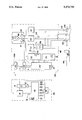
- two accessories 630 responsive to electric pulses namely a level crossing and a points switch.
- This portion of the circuit also comprises an accessory of the "all or nothing" type, namely an illumination lamp or a signal light 620.
- This installation is supplied by a unit 460 in which are generated, regulated and controlled the various electrical energies necessary for the installation.
- the remote control device of this supply unit 460 comprises on the one hand a portable radio emitter 400 and on the other hand a fixed radio receiver 450 whose outputs are connected to the control means of the supply block 460.
- the fixed radio receiver 450 and this supply unit 460 are fixed inside the same housing.
- the supply unit 460 comprises firstly a circuit 500 for transforming the mains electricity supply into low-voltage direct current.
- this circuit 500 includes a transformer reducing the mains voltage to about 18 V, followed by a rectifier diode bridge delivering this same voltage as d.c..
- Two electronic regulators also enable voltages of 12 and 5 V respectively to be derived from this first voltage of 18 V.
- a second circuit of unit 460 provided to supply the rails 600 is made up of a modulator 312 connected at one end to the 18 V of unit 500 and at the other end to the first input of an inverter switch 320 whose other input is connected to ground.
- the two outputs of this inverter swtich 320 are connected to respective rails of circuit 600.
- Modulator 312 delivers, at its output (s), a d.c. voltage comprised between 0 and 14 V depending on the control voltage at gate (i).
- This gate (i) is connected to four resistors 276 in parallel and which are respectively connected at the other end to switches each configured as a Darlington transistor connection.
- This gate (i) is moreover directly connected to a fifth switch again configured as a Darlington transistor connection.
- These five transistor assemblies are respectively controlled by five independent outputs of a microcomputer 270' forming part of a fixed radio receiver 450 described below.
- a control voltage with thirty two discrete values, thus providing as many discrete values for the output voltage (s).
- the inverter relay 320 By means of the inverter relay 320 the polarity between the two rails can be modified depending on the signal applied to its control gate (i'). For safety reasons, a mechanical relay is preferred rather than an electrical relay. Likewise, the control gate (i') is connected to a switch configured as a Darlington transistor connection itself controlled by sixth output circuit of the microcomputer 270' of radio receiver 450.
- a third circuit of unit 460 for supplying the accessories 620 operating in "all or nothing" mode is made up of a current limiting circuit 314 connected at one end to the 12 V of unit 500 and at the other end to the first terminal of accessory 620, the other terminal being connected to ground via a switch identical to the previous one, i.e. as a Darlington transistor connection directly piloted by an output circuit of the microcomputer 270' of the radio receiver 450.
- the advantage of arranging this switch close to ground is that a low control voltage is sufficient to switch it.
- the circuit 314 may comprise an electronic component whose impedance varies as a function of the difference of potential at the output and the potential at a control gate.
- a low-resistance resistor is thus placed behind this electronic component but before the accessory 620 and an electrical connection delivers the potential at the output of this resistor to the control gate of the electronic component. It is easy to understand that the difference between the potential at the output and that at the control gate is equal to the potential drop produced by the flow of current through the resistor and thus is truly representative of the strength of the direct current flowing through the accessory. Therefore, if this current strength tends to become too great for example because the accessory 620 is short-circuited, the impedance of the electronic component increases automatically which decreases this strength.
- the electronic component may be one commercialized by Messrs. THOMSON under reference LN 317.
- a fourth circuit of unit 460 designed to supply the pulse-operated accessories 630 comprises another current-limiting circuit 314 similar to the previously-described one, connected at one end to the 18 V of unit 500 and at the other end to the first terminals of each of the accessories 630. Furthermore, a high-capacitance capacitor 318 is connected at one end to the output of this circuit 314 and at the other end to ground. Finally, all of the second terminals of accessories 630 are respectively connected to switches, always in the form of Darlington transistor connections, which connections are contained together in a lower second housing 275. In fact, each accessory 630 comprises two discrete circuits: one for actuating, the other for de-actuating, two switches being provided per accessory.
- the capacitor 318 is provided for storing a sufficient electrical charge to generate a brief pulse but with a strong current, about one Amp, when a switch is closed while its circuit 314 carries a maximum current of the order of 300 milliamps. In other words, the capacitor 318 can only be charged when all of the switches of accessories 630 are open and a charging current can flow, controlled by circuit 314.
- the portable radio emitter 400 is schematically shown on the left of the Figure.
- This emitter comprises a microcomputer 270, i.e. an electronic component containing in the same housing a microprocessor, also called central processing unit, communicating via an internal data transfer line known as a "bus" with a passive ROM memory which stores data relating to action procedures (or microprocessor programs), an active RAM memory in which the necessary data for stages of actions can be written and read, as well as several series of input and/or output buffer circuits depending on the destinations or functions attributed by the program.
- This microcomputer is supplied at 5 V from a battery 50 by means of a voltage adapting and regulating circuit 55.
- Two input circuits designated by 27 and 28 are connected respectively to ground and to the circuit 55. Seven of the input buffer circuits are respectively connected to switches “1" to "5", “+” and “-”, the latter all being connected to a circuit 60 delivering from battery 50 a voltage compatible with the input circuits. Furthermore, one of the output buffer circuits is connected to the input of a fixed-frequency oscillator circuit 25 including one element serving as antenna and another element for adjusting this frequency.
- this oscillator circuit may be composed on the one hand of a simple transistor whose base forms the circuit's input, whose emitter is connected to ground and whose collector is connected to the battery 50 via a damping coil and on the other hand of an oscillator circuit, such as a parallel connection of capacitors and a coil serving as antenna, connected between the transistor's collector and base.
- the corresponding fixed radio receiver 450 comprises a first oscillator 215 having the frequency of its output signal (c) modulated by the radio-electric signals (b) received by an antenna 200b.
- this antenna 200b may also be the "plus" rail of the rail circuit 600.
- This output signal (c) is applied to the input of a demodulator-decoder circuit 225 comprising a frequency comparator whose output signal (a) is applied to one of the input circuits of a microcomputer 270'.
- this microcomputer comprises a single housing containing a microprocessor connected via an internal "bus" line to a passive ROM memory for storing data relating to the action sequence of the microprocessor and to an active RAM memory in which data necessary for operation of the microprocessor can be written and read, the input buffer circuit connected to the demodulator 225, as well as several output buffer circuits that are respectively connected to the switches 275 mentioned during the description of the supply unit 460. Finally, two input circuits (or gates) 27 and 28 are connected to the 5 V supply and to ground respectively. The circuits 215 and 225 are supplied with 12 V and the microcomputer 270' with 5 V from the circuit 500 of unit 460.
- the microcomputers in the emitter and the receiver may be of a known type, such as the model EF68HC commercialized by Messrs. THOMSON.
- a single semiconductor topography having the same functions. Because of the similarity of the architecture of the two microcomputers, and because the only differences reside essentially in the relatively simple operation set up by the pre-recorded procedures in the ROM memories, it can be envisaged that a single topography could be designed that would be fitted indifferently in the emitter or in the receiver, and with the particular connection of one or two input gates such as 27, 28 ensuring that only the necessary part of the operating procedure is brought into action.
- the above-described remote control device operates as follows.
- the microcomputer 270 When a battery 50 is fitted in the radio emitter 400, the microcomputer 270 firstly enters an initialization procedure which is read from the ROM memory. During this procedure, its microprocessor tests the state of the input circuits 27 and 28 and determines that an "emitter" role has been assigned to it during installation. Then this microprocessor passes to a waiting mode until one of the buttons "1"-"5", "+” or "-" is actuated a first time by the user. According to the actuated button, the microprocessor writes into the active RAM memory the corresponding family of pre-established codes. In other words, the microcomputer initially has seven families of codes available in a ROM memory but later makes use of only one in a RAM memory. This allows use of another portable radio emitter 400 that can be used in the surroundings, taking care however to select another code by actuating the first time a different one of the switches.
- the radio emitter 400 is ready for use.
- the microprocessor of microcomputer 270 responds to a change of state of the corresponding input buffer circuit and associates with this received signal an address of the active RAM memory, and applies the corresponding code to the output circuit that delivers a coded signal (a) to the input of oscillator 25.
- this signal (a) may be a succession of a word made up of a series of absences or presences of square waves of the order of 5 V.
- the first part of the word may characterize the family of codes used while the second part instead characterizes the button that has been pressed.
- a half word may be made up of a succession of eight square waves one of which is repeated (doubled), the position of this double square wave in relation to the others characterizes the data: family of codes, button.
- the oscillator 25 starts as soon as its input gate is at a sufficient potential and stops as soon as its input gate drops back to a potential close to zero and on the other hand that this oscillator operates at a high frequency much greater than that of the coded signal (a)
- the oscillator 25 upon receiving this signal (a) the oscillator 25 emits a radio-electric signal (b) composed of a series of the presence or absence of identical packets of pulses, each of these packets corresponding to a square wave.
- the radio signal (b) reproduces the coded signal (a) with the difference that the square waves are now replaced by packets of pulses of high frequency.
- the power applied to the antenna is small, of the order of 0.5 mW, providing very economical use of the battery 50, limiting as far as possible interference outside the building while providing a sufficient emission for the receiver 450.
- a low-consumption LED lamp associated with the emitter's antenna enables verification of the proper functioning of the emitter.
- This radio electric signal (b) is received by an antenna 200b at the input of oscillator 215 and alters its oscillation frequency. For instance, this oscillator goes from a normal frequency of 4 MHz to a second frequency of 2 MHz when packets of pulses are received.
- the frequency-modulated signal (c) is then applied to a demodulator-decoder comprising a frequency comparator and delivering a voltage of 5 V for the normal frequency and 0 V for the other and which, at the output, reconstitutes the signal (a) previously generated in the radio emitter 400.
- This signal (a) is then applied to the input of the microcomputer 270'.
- the latter also firstly goes through a self-initialisation procedure that is read from its ROM memory.
- its microprocessor firstly tests the state of the input circuits 27 and 28 and establishes that a "receiver" role has been assigned to it during installation. Then, this microprocessor waits for reception of a first signal of which it reads only the first part characterizing the family of codes set up in the emitter and which it in turn writes in identical fashion in its active memory with the codes of the associated buttons.
- tests may be carried out to check the authenticity of the received signal. For example, given that the duration of the square waves has been set at a value much greater than the usual duration of interference, one test may consist of verifying that a square wave forming part of a signal (a) transmitted by the demodulator-decoder 225 has a given minimum duration.
- the next signal (a) is read by the microprocessor of microcomputer 270' and compared with the codes previously recorded in the storage means (for instance the RAM). If no code corresponds to the second half-word received, the microprocessor equates this with interference and rejects it, i.e. it waits for reception of a new signal. If, however, the second half-word received corresponds to one of the predetermined codes, the microprocessor equates this with whichever button of the radio emitter that has been pressed in. The microprocessor can then operate according to the user's orders.
- the microcomputer 270' applies either a pulse or a saturation state to the output terminal connected with the corresponding switch of the lower housing 275.
- the associated accessory is then triggered in the usual manner.
- microcomputer 270' If the microcomputer 270' senses that the "+" button has been pressed in, it modifies the state of the switches contained in the upper housing 275 to increase by a discrete amount the control voltage at the gate (i) of modulator 310 which thus increases by one increment the voltage applied to the railway installation, hence the speed of the locomotive. If after a waiting time fixed for example at 8/10ths of a second, the word corresponding to the "+" button is still present at the input of microprocessor 270', this microprocessor realizes that the acceleration must be pursued and modifies the state of the switches again until the five gates are in the 1 (or high) state. This waiting time can be established in such a manner that full acceleration of the locomotive takes place in five seconds.
- the microcomputer 270' If, however, the microcomputer 270' senses that the "-" button has been pressed, it modifies the state of the switches contained in the upper housing 275 to reduce by a discrete amount the control voltage at the gate (i). Furthermore, the microcomputer 270' tests whether the last gate switched is not also the first of the series corresponding to zero speed. In this case, persistence of the word corresponding to the "-" button at the input of the microcomputer 270' means that the direction of motion of the locomotive must be reversed and the corresponding gate at the input (i') of the inverter relay 320 is changed.
- simultaneous pressing in of the "+” and “-” buttons corresponds to a particular code generating a series of characteristic words that are then interpreted in the microcomputer 270' to mean an emergency stop.
- this device In comparison with known radio-operated remote controls for model aeroplanes, this device has a reduced number of circuits while the form of the radio-electric signal enhances the immunity of the transmission to interference from the surroundings.
- this remote control device allows the user to move around his model train installation while continuing to transmit orders to the previously-described supply unit incorporated in unit 460.
- this device increases the interest of many enthusiasts who can now appreciate and admire all details of their their complex installations, and for a low cost. Furthermore, this device now enables installations that need no longer be confined to a single room, but may extend through several rooms or outside thereby increasing the user's pleasure.
Landscapes
- Engineering & Computer Science (AREA)
- Computer Networks & Wireless Communication (AREA)
- Toys (AREA)
- Selective Calling Equipment (AREA)
Applications Claiming Priority (4)
| Application Number | Priority Date | Filing Date | Title |
|---|---|---|---|
| FR8901565A FR2642324B1 (fr) | 1989-01-31 | 1989-01-31 | Dispositif de commande a distance pour une installation de jouet electrique sur circuit |
| FR8901565 | 1989-01-31 | ||
| FR898907748A FR2648053B2 (fr) | 1989-01-31 | 1989-06-07 | Dispositif de commande a distance pour une installation de jouet electrique sur circuit |
| FR8907748 | 1989-06-07 |
Publications (1)
| Publication Number | Publication Date |
|---|---|
| US5073750A true US5073750A (en) | 1991-12-17 |
Family
ID=26227156
Family Applications (1)
| Application Number | Title | Priority Date | Filing Date |
|---|---|---|---|
| US07/472,238 Expired - Fee Related US5073750A (en) | 1989-01-31 | 1990-01-30 | Remote control apparatus for installation of electrical toy and circuit |
Country Status (3)
| Country | Link |
|---|---|
| US (1) | US5073750A (fr) |
| EP (1) | EP0381594A1 (fr) |
| FR (1) | FR2648053B2 (fr) |
Cited By (17)
| Publication number | Priority date | Publication date | Assignee | Title |
|---|---|---|---|---|
| US5134347A (en) * | 1991-02-22 | 1992-07-28 | Comfortex Corporation | Low power consumption wireless data transmission and control system |
| WO1993006577A1 (fr) * | 1991-09-17 | 1993-04-01 | Hamilton Michael S | Systeme de commande a distance pour autorail miniature |
| US5456604A (en) * | 1993-10-20 | 1995-10-10 | Olmsted; Robert A. | Method and system for simulating vehicle operation using scale models |
| US5775647A (en) * | 1997-01-31 | 1998-07-07 | Wyatt; Michael L. | Hydraulic switch stand |
| US5846120A (en) * | 1997-02-11 | 1998-12-08 | Rokenbok Toy Company | Toy tow trailer with self-leveling hitch assembly |
| US5879221A (en) * | 1997-02-11 | 1999-03-09 | Rokenbok Toy Company | Toy bulldozer with blade float mechanism |
| US5885159A (en) * | 1996-08-13 | 1999-03-23 | Rokenbok Toy Company | System for, and method of, controlling the operation of toys |
| US5944607A (en) * | 1995-12-29 | 1999-08-31 | Rokenbok Toy Company | Remote control system for operating toys |
| US5952797A (en) * | 1996-06-03 | 1999-09-14 | Roessler; Elfriede | Model vehicle, particularly model railway vehicle |
| US5964640A (en) * | 1997-02-11 | 1999-10-12 | Rokenbok Toy Company | Toy dump truck with automatic dumper mechanism |
| US5989096A (en) * | 1997-02-11 | 1999-11-23 | Rokenbok Toy Company | Toy fork lift vehicle with improved steering |
| US6247994B1 (en) | 1998-02-11 | 2001-06-19 | Rokenbok Toy Company | System and method for communicating with and controlling toy accessories |
| US6320346B1 (en) * | 2000-08-11 | 2001-11-20 | Atlas Model Railroad Company, Incorporated | DCC decoder for model railroad |
| US6457681B1 (en) | 2000-12-07 | 2002-10-01 | Mike's Train House, Inc. | Control, sound, and operating system for model trains |
| US20060071620A1 (en) * | 2004-10-06 | 2006-04-06 | Zahornacky Jon F | Model train direction control device |
| US20060202645A1 (en) * | 1998-11-04 | 2006-09-14 | Denen Dennis J | Control and motor arrangement for use in model train |
| US7553211B1 (en) | 1997-02-11 | 2009-06-30 | Deangelis Peter C | System and method for controlling the operation of toys |
Families Citing this family (2)
| Publication number | Priority date | Publication date | Assignee | Title |
|---|---|---|---|---|
| GB2312631B (en) * | 1996-04-30 | 1998-03-11 | Artin Ind Co Ltd | Electric toy car racing track controller system |
| WO2006084965A1 (fr) * | 2005-02-08 | 2006-08-17 | Wany Sa | Procédé et système pour contrôler la vitesse de modèles réduits sur un circuit |
Citations (12)
| Publication number | Priority date | Publication date | Assignee | Title |
|---|---|---|---|---|
| FR1494132A (fr) * | 1966-05-16 | 1967-09-08 | Csf | Système radioélectrique de localisation de rames de véhicules circulant sur une piste directrice |
| FR2315295A1 (fr) * | 1975-06-23 | 1977-01-21 | Bacchelli Sancio | Dispositif electronique pour le controle automatique du mouvement de trains electriques jouets |
| FR2364667A1 (fr) * | 1976-09-21 | 1978-04-14 | Auergesellschaft Gmbh | Cartouche chimique pour appareils de protection respiratoires |
| FR2380048A1 (fr) * | 1977-02-11 | 1978-09-08 | Kubryk Gerard | Procede et systeme de telecommande pour mobiles, notamment pour modeles reduits |
| DE2741154A1 (de) * | 1977-09-13 | 1979-03-22 | Maerklin & Cie Gmbh Geb | Anordnung zum betreiben eines triebfahrzeuges einer spielzeugeisenbahnanlage |
| US4390877A (en) * | 1980-07-31 | 1983-06-28 | Curran Kenneth J | Remote control systems for toy vehicles, and the like |
| US4449114A (en) * | 1980-03-27 | 1984-05-15 | Dataspeed, Inc. | System for identifying and displaying data transmitted by way of unique identifying frequencies from multiple vehicles |
| DE3301732A1 (de) * | 1983-01-20 | 1984-07-26 | Multiplex Elektronik GmbH, 7532 Niefern-Öschelbronn | Sender mit mikroprozessor zur fernsteuerung von modellen |
| DE3309662A1 (de) * | 1983-03-17 | 1984-09-27 | Heinz-Jürgen Dipl.-Ing. Roth | Verfahren und vorrichtung zum selektiven ansteuern von empfaengern, insbesondere von modellbahnfahrzeugen, weichen, signalen, beleuchtung und schranken einer modellbahnanlage |
| US4572996A (en) * | 1983-04-22 | 1986-02-25 | Gebruder Marklin & Cie. Gesellschaft mit beschrankter Haftung | Control unit for model vehicles |
| US4791570A (en) * | 1985-05-02 | 1988-12-13 | Eaton-Kenway, Inc. | Guide wire communication system and method |
| US4902948A (en) * | 1985-05-02 | 1990-02-20 | Eaton-Kenway, Inc. | Guide wire communication system and method |
-
1989
- 1989-06-07 FR FR898907748A patent/FR2648053B2/fr not_active Expired - Lifetime
-
1990
- 1990-01-29 EP EP90420039A patent/EP0381594A1/fr not_active Withdrawn
- 1990-01-30 US US07/472,238 patent/US5073750A/en not_active Expired - Fee Related
Patent Citations (12)
| Publication number | Priority date | Publication date | Assignee | Title |
|---|---|---|---|---|
| FR1494132A (fr) * | 1966-05-16 | 1967-09-08 | Csf | Système radioélectrique de localisation de rames de véhicules circulant sur une piste directrice |
| FR2315295A1 (fr) * | 1975-06-23 | 1977-01-21 | Bacchelli Sancio | Dispositif electronique pour le controle automatique du mouvement de trains electriques jouets |
| FR2364667A1 (fr) * | 1976-09-21 | 1978-04-14 | Auergesellschaft Gmbh | Cartouche chimique pour appareils de protection respiratoires |
| FR2380048A1 (fr) * | 1977-02-11 | 1978-09-08 | Kubryk Gerard | Procede et systeme de telecommande pour mobiles, notamment pour modeles reduits |
| DE2741154A1 (de) * | 1977-09-13 | 1979-03-22 | Maerklin & Cie Gmbh Geb | Anordnung zum betreiben eines triebfahrzeuges einer spielzeugeisenbahnanlage |
| US4449114A (en) * | 1980-03-27 | 1984-05-15 | Dataspeed, Inc. | System for identifying and displaying data transmitted by way of unique identifying frequencies from multiple vehicles |
| US4390877A (en) * | 1980-07-31 | 1983-06-28 | Curran Kenneth J | Remote control systems for toy vehicles, and the like |
| DE3301732A1 (de) * | 1983-01-20 | 1984-07-26 | Multiplex Elektronik GmbH, 7532 Niefern-Öschelbronn | Sender mit mikroprozessor zur fernsteuerung von modellen |
| DE3309662A1 (de) * | 1983-03-17 | 1984-09-27 | Heinz-Jürgen Dipl.-Ing. Roth | Verfahren und vorrichtung zum selektiven ansteuern von empfaengern, insbesondere von modellbahnfahrzeugen, weichen, signalen, beleuchtung und schranken einer modellbahnanlage |
| US4572996A (en) * | 1983-04-22 | 1986-02-25 | Gebruder Marklin & Cie. Gesellschaft mit beschrankter Haftung | Control unit for model vehicles |
| US4791570A (en) * | 1985-05-02 | 1988-12-13 | Eaton-Kenway, Inc. | Guide wire communication system and method |
| US4902948A (en) * | 1985-05-02 | 1990-02-20 | Eaton-Kenway, Inc. | Guide wire communication system and method |
Non-Patent Citations (2)
| Title |
|---|
| Copy of Radio Mento, vol. 30, No. 6, Jun. 1964, pp. 488 493, entitled Frensteuranlagen . * |
| Copy of Radio Mento, vol. 30, No. 6, Jun. 1964, pp. 488-493, entitled "Frensteuranlagen". |
Cited By (28)
| Publication number | Priority date | Publication date | Assignee | Title |
|---|---|---|---|---|
| US5134347A (en) * | 1991-02-22 | 1992-07-28 | Comfortex Corporation | Low power consumption wireless data transmission and control system |
| WO1993006577A1 (fr) * | 1991-09-17 | 1993-04-01 | Hamilton Michael S | Systeme de commande a distance pour autorail miniature |
| US5456604A (en) * | 1993-10-20 | 1995-10-10 | Olmsted; Robert A. | Method and system for simulating vehicle operation using scale models |
| US5944607A (en) * | 1995-12-29 | 1999-08-31 | Rokenbok Toy Company | Remote control system for operating toys |
| US5952797A (en) * | 1996-06-03 | 1999-09-14 | Roessler; Elfriede | Model vehicle, particularly model railway vehicle |
| US5885159A (en) * | 1996-08-13 | 1999-03-23 | Rokenbok Toy Company | System for, and method of, controlling the operation of toys |
| US5775647A (en) * | 1997-01-31 | 1998-07-07 | Wyatt; Michael L. | Hydraulic switch stand |
| US5879221A (en) * | 1997-02-11 | 1999-03-09 | Rokenbok Toy Company | Toy bulldozer with blade float mechanism |
| US5846120A (en) * | 1997-02-11 | 1998-12-08 | Rokenbok Toy Company | Toy tow trailer with self-leveling hitch assembly |
| US5964640A (en) * | 1997-02-11 | 1999-10-12 | Rokenbok Toy Company | Toy dump truck with automatic dumper mechanism |
| US5989096A (en) * | 1997-02-11 | 1999-11-23 | Rokenbok Toy Company | Toy fork lift vehicle with improved steering |
| US7553211B1 (en) | 1997-02-11 | 2009-06-30 | Deangelis Peter C | System and method for controlling the operation of toys |
| US6247994B1 (en) | 1998-02-11 | 2001-06-19 | Rokenbok Toy Company | System and method for communicating with and controlling toy accessories |
| US7298103B2 (en) | 1998-11-04 | 2007-11-20 | Lionel L.L.C. | Control and motor arrangement for use in model train |
| US7307394B1 (en) | 1998-11-04 | 2007-12-11 | Lionel L.L.C. | Control and motor arrangement for use in model train |
| US7880414B2 (en) * | 1998-11-04 | 2011-02-01 | Lionel L.L.C. | Control and motor arrangement for use in model train |
| US20100094483A1 (en) * | 1998-11-04 | 2010-04-15 | Denen Dennis J | Control and motor arrangement for use in model train |
| US7656110B2 (en) | 1998-11-04 | 2010-02-02 | Lionel L.L.C. | Control and motor arrangement for use in model train |
| US20060202645A1 (en) * | 1998-11-04 | 2006-09-14 | Denen Dennis J | Control and motor arrangement for use in model train |
| US6320346B1 (en) * | 2000-08-11 | 2001-11-20 | Atlas Model Railroad Company, Incorporated | DCC decoder for model railroad |
| US7210656B2 (en) | 2000-12-07 | 2007-05-01 | Mike's Train House, Inc. | Control, sound, and operating system for model trains |
| US6457681B1 (en) | 2000-12-07 | 2002-10-01 | Mike's Train House, Inc. | Control, sound, and operating system for model trains |
| US6604641B2 (en) | 2000-12-07 | 2003-08-12 | Mike's Train House, Inc. | Low-power electrically operated coupler |
| US6655640B2 (en) | 2000-12-07 | 2003-12-02 | Mike's Train House, Inc. | Control, sound, and operating system for model trains |
| US6619594B2 (en) | 2000-12-07 | 2003-09-16 | Mike's Train House, Inc. | Control, sound, and operating system for model trains |
| US8262034B2 (en) | 2000-12-07 | 2012-09-11 | Mike's Train House, Inc. | Control, sound, and operating system for model trains |
| US7132807B2 (en) * | 2004-10-06 | 2006-11-07 | Zahornacky Jon F | Model train direction control device |
| US20060071620A1 (en) * | 2004-10-06 | 2006-04-06 | Zahornacky Jon F | Model train direction control device |
Also Published As
| Publication number | Publication date |
|---|---|
| EP0381594A1 (fr) | 1990-08-08 |
| FR2648053B2 (fr) | 1993-01-08 |
| FR2648053A2 (fr) | 1990-12-14 |
Similar Documents
| Publication | Publication Date | Title |
|---|---|---|
| US5073750A (en) | Remote control apparatus for installation of electrical toy and circuit | |
| US5448142A (en) | Signaling techniques for DC track powered model railroads | |
| US7429931B2 (en) | Proximity control of on-board processor-based model train sound and control system | |
| JP2689078B2 (ja) | トランスミッタ−制御装置 | |
| US10434429B2 (en) | Model train control system | |
| US6457681B1 (en) | Control, sound, and operating system for model trains | |
| US4219962A (en) | Toy vehicle | |
| US7855633B2 (en) | Remote control automatic appliance activation | |
| US20040200933A1 (en) | Model vehicle detection of ID and direction | |
| JPH0413920B2 (fr) | ||
| US20070001058A1 (en) | Model railroad control and sound systems | |
| US3211111A (en) | Multi-channel carrier current control system | |
| CN109621448A (zh) | 一种玩具车编程控制方法、装置及可编程玩具车 | |
| GB1504176A (en) | Control current generators primarily for use in central dictation systems and central dictation systems incorporating such generators | |
| US3366855A (en) | Garage door remote control system | |
| US4367470A (en) | Door operation control apparatus | |
| EP0004699A1 (fr) | Système de commande pour trains miniatures | |
| US3355643A (en) | Plural remote controllers for plural motors using a common power connection | |
| Ursu et al. | Comparative Study of the Analog and Digital Operation for Miniature Railway Systems | |
| US6555979B2 (en) | System and method for controlling electrical current flow as a function of detected sound volume | |
| JPS61144132A (ja) | 送信器 | |
| GB2305281A (en) | Transmitter control | |
| SU1555152A1 (ru) | Устройство дл телеуправлени локомативами | |
| WO1993006577A1 (fr) | Systeme de commande a distance pour autorail miniature | |
| EP1599264A1 (fr) | Modele de vehicule et son procede de fonctionnement |
Legal Events
| Date | Code | Title | Description |
|---|---|---|---|
| AS | Assignment |
Owner name: JOUEF INDUSTRIES S.A., FRANCE Free format text: ASSIGNMENT OF ASSIGNORS INTEREST.;ASSIGNOR:CORON, M. JEAN-PIERRE;REEL/FRAME:005287/0890 Effective date: 19900406 |
|
| FPAY | Fee payment |
Year of fee payment: 4 |
|
| REMI | Maintenance fee reminder mailed | ||
| LAPS | Lapse for failure to pay maintenance fees | ||
| FP | Lapsed due to failure to pay maintenance fee |
Effective date: 19991217 |
|
| STCH | Information on status: patent discontinuation |
Free format text: PATENT EXPIRED DUE TO NONPAYMENT OF MAINTENANCE FEES UNDER 37 CFR 1.362 |