US5073737A - Magnetic bearing device - Google Patents
Magnetic bearing device Download PDFInfo
- Publication number
- US5073737A US5073737A US07/560,460 US56046090A US5073737A US 5073737 A US5073737 A US 5073737A US 56046090 A US56046090 A US 56046090A US 5073737 A US5073737 A US 5073737A
- Authority
- US
- United States
- Prior art keywords
- armature disk
- coil
- pole pieces
- sensor
- control coil
- Prior art date
- Legal status (The legal status is an assumption and is not a legal conclusion. Google has not performed a legal analysis and makes no representation as to the accuracy of the status listed.)
- Expired - Fee Related
Links
Images
Classifications
-
- F—MECHANICAL ENGINEERING; LIGHTING; HEATING; WEAPONS; BLASTING
- F16—ENGINEERING ELEMENTS AND UNITS; GENERAL MEASURES FOR PRODUCING AND MAINTAINING EFFECTIVE FUNCTIONING OF MACHINES OR INSTALLATIONS; THERMAL INSULATION IN GENERAL
- F16C—SHAFTS; FLEXIBLE SHAFTS; ELEMENTS OR CRANKSHAFT MECHANISMS; ROTARY BODIES OTHER THAN GEARING ELEMENTS; BEARINGS
- F16C32/00—Bearings not otherwise provided for
- F16C32/04—Bearings not otherwise provided for using magnetic or electric supporting means
- F16C32/0406—Magnetic bearings
- F16C32/044—Active magnetic bearings
- F16C32/0459—Details of the magnetic circuit
- F16C32/0461—Details of the magnetic circuit of stationary parts of the magnetic circuit
- F16C32/0465—Details of the magnetic circuit of stationary parts of the magnetic circuit with permanent magnets provided in the magnetic circuit of the electromagnets
-
- F—MECHANICAL ENGINEERING; LIGHTING; HEATING; WEAPONS; BLASTING
- F16—ENGINEERING ELEMENTS AND UNITS; GENERAL MEASURES FOR PRODUCING AND MAINTAINING EFFECTIVE FUNCTIONING OF MACHINES OR INSTALLATIONS; THERMAL INSULATION IN GENERAL
- F16C—SHAFTS; FLEXIBLE SHAFTS; ELEMENTS OR CRANKSHAFT MECHANISMS; ROTARY BODIES OTHER THAN GEARING ELEMENTS; BEARINGS
- F16C32/00—Bearings not otherwise provided for
- F16C32/04—Bearings not otherwise provided for using magnetic or electric supporting means
- F16C32/0406—Magnetic bearings
- F16C32/044—Active magnetic bearings
- F16C32/0444—Details of devices to control the actuation of the electromagnets
- F16C32/0446—Determination of the actual position of the moving member, e.g. details of sensors
- F16C32/0448—Determination of the actual position of the moving member, e.g. details of sensors by using the electromagnet itself as sensor, e.g. sensorless magnetic bearings
-
- F—MECHANICAL ENGINEERING; LIGHTING; HEATING; WEAPONS; BLASTING
- F16—ENGINEERING ELEMENTS AND UNITS; GENERAL MEASURES FOR PRODUCING AND MAINTAINING EFFECTIVE FUNCTIONING OF MACHINES OR INSTALLATIONS; THERMAL INSULATION IN GENERAL
- F16C—SHAFTS; FLEXIBLE SHAFTS; ELEMENTS OR CRANKSHAFT MECHANISMS; ROTARY BODIES OTHER THAN GEARING ELEMENTS; BEARINGS
- F16C32/00—Bearings not otherwise provided for
- F16C32/04—Bearings not otherwise provided for using magnetic or electric supporting means
- F16C32/0406—Magnetic bearings
- F16C32/044—Active magnetic bearings
- F16C32/0474—Active magnetic bearings for rotary movement
- F16C32/0476—Active magnetic bearings for rotary movement with active support of one degree of freedom, e.g. axial magnetic bearings
Definitions
- This invention relates to a magnetic bearing device.
- An object the invention is to provide a magnetic bearing device of compact construction by which the linear displacement output is obtained.
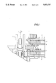
- FIG. 1 is a longitudinal sectional view showing an embodiment of the magnetic bearing device according to this invention
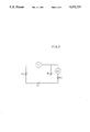
- FIG. 2 is an equivalent circuit diagram of the above device
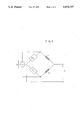
- FIG. 3 is a schematic diagram showing the working principle of the displacement detecting sensor.
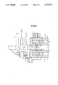
- FIG. 4 is a longitudinal sectional view of another embodiment.
- numeral 1 indicates a main rotary shaft which is rotatably provided with an armature disk 2 thereby forming an integral unit.
- a pair of bearing elements 3, 3 are disposed on opposite sides in the axial direction of the armature disk 2 putting the disk 2 therebetween.
- Each of the bearing elements 3, 3 comprises a pair of pole pieces 5, 6 mounted on two pole faces of a permanent magnet 4 along with a control coil 7.
- Each of the pole pieces 5, 6 has a part extending in parallel with the armature disk 2 and a top end part further extending from the mentioned part to a position adjacent the armature disk.
- a control coil 7 is disposed between each mentioned pair of pole pieces 5, 6 at a position nearer to the front end side than the permanent magnet 4.
- a sensor coil 8 is disposed at a position closer to the front end side than the mentioned control coil 7. The sensor coil 8 is wound in the same direction as the mentioned control coil 7.
- first and second gaps 11, 12 are respectively formed on the tip end sides of the pole pieces 5, 6, and a leakage magnetic path 13 is formed on the base end sides of the pole pieces 5, 6, of which the equivalent circuit is shown in FIG. 2.
- reference EO indicates the magnetomotive force of the permanent magnet 4
- RO indicates internal magnetic resistance thereof
- NI is the magnetic force of the control coil 7
- N is the number of turns in the control coil and I is the control
- RL indicates magnetic resistance for leakage flux
- R1 indicates magnetic resistance for the first gap 11
- R2 indicates magnetic resistance for the second gap 12.
- the magnetic resistance of the magnetic path of the control coil 7 can be optimized by enlarging the gap between pole faces N and S of the permanent magnet 4, increasing the internal magnetic resistance RO (for instance, by forming the pole pieces 5, 6 of some soft magnetic substance) and forming the leakage path of the permanent magnet 4.
- Control characteristics with control current can be improved by disposing the control coil 7 on the side nearer to the front end than the permanent magnet 4. As a result of this, not only can unbalanced spring constants due to the displacement of the armature disk be reduced, but also the entire construction can be simplified.
- FIG. 3 is a schematic diagram showing the principle of displacement detection by a displacement detecting sensor.
- the displacement detecting sensor comprises the sensor coil 8 and the armature disk 2 (magnetic substance), and a high frequency current (about 50 KHz) is applied to the coil 8.
- a high frequency current about 50 KHz
- inductance of the coil 8 varies in such a manner that the amplitude of the high frequency applied to the coil 8 is modulated.
- Such a modulated amount is detected by a detector as displacement.
- a detector circuit is formed into a bridge comprising two impedances Z0, Z0 and two sensor coils L1, L2 so that the displacement signal is outputted by a detection circuit, after differentially detecting the modulated amount.
- Noise at the time of composing the control coil 7 and the sensor coil 8 together is not extremely high, despite a strong magnetic field being generated in the control coil 7 of which the attractive force is increased, though the amount of inductance variation reaches a certain value. This is because the sensor coil 8 is relatively distant from the armature disk 2. On the other hand, also in the control coil 7 of which the attractive force is decreased, the amount of inductance variation of the sensor coil 8 is almost the same as the mentioned certain value, despite the magnetic field generated being not so strong. This is because the distance between the sensor coil 8 and the armature disk 2 is shorter. In this manner, adoption of the differential detection system described above makes it possible to offset the amount of variation between each other, and there is no detection in the form of a displaced component, eventually resulting in accurate and precise detection of displacement.
- L1, L2 inductances of sensor coil
- Ns number of turns in the sensor coil
- V is a high frequency voltage of several 10 Khz of which the amplitude is in proportion to displacement
- any displacement signal can be outputted by eliminating the high frequency component through detection.
- the axial displacement detection mechanism since the sensor coil 8 has its magnetic path in common with the control coil 7, space can be saved. Furthermore, as a result of employing the differential detection mechanism as described above, the output of the sensor is zero when the armature disk 2 is in the center between the two bearing elements 3, 3. Thus, not only can irregularity among individual components be reduced but also the linear sensor output with respect to displacement can be obtained.
- the sensor coil 8 it is also preferable to dispose the sensor coil 8 at a position as shown in FIG. 4 outside the pole pieces 6 instead of between the pole pieces 5, 6 as shown in FIG. 1.
Landscapes
- Engineering & Computer Science (AREA)
- General Engineering & Computer Science (AREA)
- Mechanical Engineering (AREA)
- Physics & Mathematics (AREA)
- Electromagnetism (AREA)
- Magnetic Bearings And Hydrostatic Bearings (AREA)
Abstract
Description
1/[1+RO/(1+RO/R1)(R1+R2)]
V=-V0×/2×0
Claims (2)
Applications Claiming Priority (2)
| Application Number | Priority Date | Filing Date | Title |
|---|---|---|---|
| JP63254621A JP2961117B2 (en) | 1988-10-07 | 1988-10-07 | Magnetic bearing device |
| JP63-254621 | 1998-10-07 |
Related Parent Applications (1)
| Application Number | Title | Priority Date | Filing Date |
|---|---|---|---|
| US07418316 Continuation | 1989-10-06 |
Publications (1)
| Publication Number | Publication Date |
|---|---|
| US5073737A true US5073737A (en) | 1991-12-17 |
Family
ID=17267576
Family Applications (1)
| Application Number | Title | Priority Date | Filing Date |
|---|---|---|---|
| US07/560,460 Expired - Fee Related US5073737A (en) | 1988-10-07 | 1990-07-27 | Magnetic bearing device |
Country Status (5)
| Country | Link |
|---|---|
| US (1) | US5073737A (en) |
| EP (1) | EP0362881B1 (en) |
| JP (1) | JP2961117B2 (en) |
| KR (1) | KR0153451B1 (en) |
| DE (1) | DE68912490T2 (en) |
Cited By (3)
| Publication number | Priority date | Publication date | Assignee | Title |
|---|---|---|---|---|
| US5660397A (en) * | 1994-09-23 | 1997-08-26 | Holtkamp; William H. | Devices employing a liquid-free medium |
| DE19823630A1 (en) * | 1998-05-27 | 1999-12-02 | Pm Dm Gmbh | Motor bearings for fast rotating small motors |
| EP1679492A1 (en) * | 2005-01-11 | 2006-07-12 | Mecos Traxler AG | Eddy-current sensor and magnetic bearing device |
Families Citing this family (3)
| Publication number | Priority date | Publication date | Assignee | Title |
|---|---|---|---|---|
| GB2269862B (en) * | 1992-08-22 | 1996-05-08 | Glacier Metal Co Ltd | Electromagnetic bearing arrangement |
| KR950034989A (en) * | 1994-05-30 | 1995-12-30 | 이형도 | Thrust Magnetic Bearings |
| US6008558A (en) * | 1998-09-17 | 1999-12-28 | Sundstrand Corporation | L-shaped magnetic thrust bearing |
Citations (5)
| Publication number | Priority date | Publication date | Assignee | Title |
|---|---|---|---|---|
| US4167296A (en) * | 1977-12-30 | 1979-09-11 | Sperry Rand Corporation | Protective control system for magnetic suspension and magnetically suspended devices |
| US4353602A (en) * | 1977-01-12 | 1982-10-12 | Societe Europeenne De Propulsion | Axial electromagnetic bearing for smooth shafts of large diameter |
| US4609869A (en) * | 1983-04-13 | 1986-09-02 | Electro Corporation | Magnetic sensor and circuit for detecting the edge of a target as it passes the centerline of the sensor |
| EP0311122A1 (en) * | 1987-10-07 | 1989-04-12 | Ebara Research Co., Ltd. | Radial magnetic bearing system |
| US4920291A (en) * | 1989-01-19 | 1990-04-24 | Contraves Goerz Corporation | Magnetic thrust bearing with high force modulation capability |
Family Cites Families (4)
| Publication number | Priority date | Publication date | Assignee | Title |
|---|---|---|---|---|
| DE2355104A1 (en) * | 1973-11-03 | 1975-05-15 | Bbc Brown Boveri & Cie | Rotating spindle with electromagnet controlled axial position - soft iron disc rotates on spindle between annular windings |
| JPS5881217A (en) * | 1981-11-11 | 1983-05-16 | Seiko Instr & Electronics Ltd | Five dimentional freedom control type magnetic bearing device |
| EP0192836A3 (en) * | 1985-03-01 | 1988-07-20 | Maschinenfabrik Rieter Ag | Use of a magnetic bearing |
| US4642501A (en) * | 1985-10-15 | 1987-02-10 | Sperry Corporation | Magnetic suspension and pointing system with flux feedback linearization |
-
1988
- 1988-10-07 JP JP63254621A patent/JP2961117B2/en not_active Expired - Lifetime
-
1989
- 1989-10-06 EP EP89118607A patent/EP0362881B1/en not_active Expired - Lifetime
- 1989-10-06 DE DE68912490T patent/DE68912490T2/en not_active Expired - Fee Related
- 1989-10-07 KR KR1019890014499A patent/KR0153451B1/en not_active Expired - Fee Related
-
1990
- 1990-07-27 US US07/560,460 patent/US5073737A/en not_active Expired - Fee Related
Patent Citations (7)
| Publication number | Priority date | Publication date | Assignee | Title |
|---|---|---|---|---|
| US4353602A (en) * | 1977-01-12 | 1982-10-12 | Societe Europeenne De Propulsion | Axial electromagnetic bearing for smooth shafts of large diameter |
| US4167296A (en) * | 1977-12-30 | 1979-09-11 | Sperry Rand Corporation | Protective control system for magnetic suspension and magnetically suspended devices |
| US4609869A (en) * | 1983-04-13 | 1986-09-02 | Electro Corporation | Magnetic sensor and circuit for detecting the edge of a target as it passes the centerline of the sensor |
| EP0311122A1 (en) * | 1987-10-07 | 1989-04-12 | Ebara Research Co., Ltd. | Radial magnetic bearing system |
| US4879500A (en) * | 1987-10-07 | 1989-11-07 | Ebara Research Co., Ltd. | Controller for magnetic bearing system |
| US4942321A (en) * | 1987-10-07 | 1990-07-17 | Yoichi Kanemitsu | Radial magnetic bearing system |
| US4920291A (en) * | 1989-01-19 | 1990-04-24 | Contraves Goerz Corporation | Magnetic thrust bearing with high force modulation capability |
Cited By (7)
| Publication number | Priority date | Publication date | Assignee | Title |
|---|---|---|---|---|
| US5660397A (en) * | 1994-09-23 | 1997-08-26 | Holtkamp; William H. | Devices employing a liquid-free medium |
| US5704613A (en) * | 1994-09-23 | 1998-01-06 | Holtkamp; William H. | Methods for sealing and unsealing using a magnetically permeable solid-based medium |
| DE19823630A1 (en) * | 1998-05-27 | 1999-12-02 | Pm Dm Gmbh | Motor bearings for fast rotating small motors |
| US6504279B1 (en) | 1998-05-27 | 2003-01-07 | Precision Motors Deutsche Minebea Gmbh | Motor mount for small high speed motors |
| DE19823630C2 (en) * | 1998-05-27 | 2003-08-21 | Pmdm Prec Motors Deutsche Mine | Motor bearings for fast rotating small motors |
| EP1679492A1 (en) * | 2005-01-11 | 2006-07-12 | Mecos Traxler AG | Eddy-current sensor and magnetic bearing device |
| WO2006074560A3 (en) * | 2005-01-11 | 2006-08-31 | Mecos Traxler Ag | Eddy-current sensor and magnetic bearing device |
Also Published As
| Publication number | Publication date |
|---|---|
| KR900006696A (en) | 1997-05-08 |
| DE68912490T2 (en) | 1994-08-11 |
| DE68912490D1 (en) | 1994-03-03 |
| EP0362881A2 (en) | 1990-04-11 |
| JPH02102919A (en) | 1990-04-16 |
| JP2961117B2 (en) | 1999-10-12 |
| KR0153451B1 (en) | 1998-12-01 |
| EP0362881B1 (en) | 1994-01-19 |
| EP0362881A3 (en) | 1990-07-04 |
Similar Documents
| Publication | Publication Date | Title |
|---|---|---|
| US5068558A (en) | Magnetic bearing device | |
| KR920006499B1 (en) | Torque sensor | |
| US20050127905A1 (en) | Eddy current sensors | |
| US3942045A (en) | Speed or angular position electromagnetic transducer | |
| US5606254A (en) | Rotation sensor employing coil wound on assembly of a core interposed between two magnets | |
| US5073737A (en) | Magnetic bearing device | |
| US5194805A (en) | Inductance-type displacement sensor for eliminating inaccuracies due to external magnetic fields | |
| WO1994014027A1 (en) | Rotary transducer | |
| JP2000161989A (en) | Rotation sensor | |
| EP0562799B1 (en) | Transducers | |
| JPS6243429B2 (en) | ||
| CA2560620C (en) | Active magnetic bearing with automatic detection of the position thereof | |
| JP2608498B2 (en) | Magnetostrictive torque sensor | |
| US3641377A (en) | Ignition timing pulse generator for a contactless ignition system of internal combustion engines | |
| JPH03269330A (en) | Torque sensor | |
| SU750270A1 (en) | Electric constant current contact-free machine rotor-position sensor | |
| JP2673479B2 (en) | Magnetic bearing device | |
| JPH10257745A (en) | Stepping motor with mechanism for detecting rotor position | |
| JPH01161701A (en) | Solenoid with position sensor | |
| JPS6145449Y2 (en) | ||
| JPH05118331A (en) | Magnetic bearing device | |
| SU794526A1 (en) | Barkhausen effect-based speed sensor | |
| JPH0566102A (en) | Position detector | |
| KR940019408A (en) | Bending Size Detection Device of Shaft | |
| JPH04361101A (en) | Position detector |
Legal Events
| Date | Code | Title | Description |
|---|---|---|---|
| REMI | Maintenance fee reminder mailed | ||
| FEPP | Fee payment procedure |
Free format text: PAYOR NUMBER ASSIGNED (ORIGINAL EVENT CODE: ASPN); ENTITY STATUS OF PATENT OWNER: SMALL ENTITY Free format text: PAT HLDR NO LONGER CLAIMS SMALL ENT STAT AS INDIV INVENTOR (ORIGINAL EVENT CODE: LSM1); ENTITY STATUS OF PATENT OWNER: SMALL ENTITY |
|
| FEPP | Fee payment procedure |
Free format text: PAT HOLDER CLAIMS SMALL ENTITY STATUS - SMALL BUSINESS (ORIGINAL EVENT CODE: SM02); ENTITY STATUS OF PATENT OWNER: SMALL ENTITY |
|
| REFU | Refund |
Free format text: REFUND OF EXCESS PAYMENTS PROCESSED (ORIGINAL EVENT CODE: R169); ENTITY STATUS OF PATENT OWNER: SMALL ENTITY |
|
| FPAY | Fee payment |
Year of fee payment: 4 |
|
| SULP | Surcharge for late payment | ||
| REMI | Maintenance fee reminder mailed | ||
| LAPS | Lapse for failure to pay maintenance fees | ||
| FP | Lapsed due to failure to pay maintenance fee |
Effective date: 19991217 |
|
| STCH | Information on status: patent discontinuation |
Free format text: PATENT EXPIRED DUE TO NONPAYMENT OF MAINTENANCE FEES UNDER 37 CFR 1.362 |