US5073701A - Arrangement in a range or a cooking hob - Google Patents
Arrangement in a range or a cooking hob Download PDFInfo
- Publication number
- US5073701A US5073701A US07/475,160 US47516090A US5073701A US 5073701 A US5073701 A US 5073701A US 47516090 A US47516090 A US 47516090A US 5073701 A US5073701 A US 5073701A
- Authority
- US
- United States
- Prior art keywords
- setting
- hot plate
- power
- end time
- timing
- Prior art date
- Legal status (The legal status is an assumption and is not a legal conclusion. Google has not performed a legal analysis and makes no representation as to the accuracy of the status listed.)
- Expired - Fee Related
Links
- 238000010411 cooking Methods 0.000 title claims abstract description 11
- 238000001514 detection method Methods 0.000 claims 2
- 238000010586 diagram Methods 0.000 description 4
- 238000010438 heat treatment Methods 0.000 description 1
Images
Classifications
-
- G—PHYSICS
- G05—CONTROLLING; REGULATING
- G05D—SYSTEMS FOR CONTROLLING OR REGULATING NON-ELECTRIC VARIABLES
- G05D23/00—Control of temperature
- G05D23/19—Control of temperature characterised by the use of electric means
- G05D23/1951—Control of temperature characterised by the use of electric means with control of the working time of a temperature controlling device
-
- F—MECHANICAL ENGINEERING; LIGHTING; HEATING; WEAPONS; BLASTING
- F24—HEATING; RANGES; VENTILATING
- F24C—DOMESTIC STOVES OR RANGES ; DETAILS OF DOMESTIC STOVES OR RANGES, OF GENERAL APPLICATION
- F24C15/00—Details
- F24C15/10—Tops, e.g. hot plates; Rings
- F24C15/102—Tops, e.g. hot plates; Rings electrically heated
- F24C15/106—Tops, e.g. hot plates; Rings electrically heated electric circuits
-
- H—ELECTRICITY
- H05—ELECTRIC TECHNIQUES NOT OTHERWISE PROVIDED FOR
- H05B—ELECTRIC HEATING; ELECTRIC LIGHT SOURCES NOT OTHERWISE PROVIDED FOR; CIRCUIT ARRANGEMENTS FOR ELECTRIC LIGHT SOURCES, IN GENERAL
- H05B3/00—Ohmic-resistance heating
- H05B3/68—Heating arrangements specially adapted for cooking plates or analogous hot-plates
- H05B3/74—Non-metallic plates, e.g. vitroceramic, ceramic or glassceramic hobs, also including power or control circuits
- H05B3/746—Protection, e.g. overheat cutoff, hot plate indicator
Definitions
- the present invention relates to electric ranges or cooking hobs in general and, more particularly, to a device which automatically disconnects the power to the range or cooking hob after a predetermined time of unattended operation.
- ranges and cooking hobs most often hot plates are being controlled such that the desired power level is set by a setting knob and then the power set is operating until the hot plate is switched off.
- thermostat-controlled hot plates are provided and in these it will be achieved that the hot plate cannot assume a dangerously high temperature.
- the range is equipped with at least one high power hot plate, a so-called quick hot plate, and if forgotten when set at the highest power level the hot plate can assume very high temperatures which, under certain circumstances, may cause a fire or result in other damages.
- This object is achieved in a range or a cooking hob having characteristic features which include timing means which cooperate with detecting means such that the power to the cooking hob or hot plate is disconnected at the end of the time determined by the timing means.
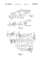
- FIG. 1 schematically shows a cooking hob having four hot plates
- FIG. 2 is a schematic diagram of a circuit for the time-controlled disconnection of a hot plate
- FIG. 3 is an embodiment according to FIG. 2 which has been modified to the effect that the time at which the hot plate is disconnected be varied with respect to the power level or temperature set;
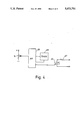
- FIG. 4 finally, is a schematic diagram of a microprocessor-based circuit.
- FIG. 1 a cooking hob 10 is shown having four hot plates 11 and a panel 12 at the front edge of the hob on which setting knobs 13 are disposed for the setting of the desired power level or temperature for each respective hot plate.
- FIG. 2 a circuit diagram is shown for a device for the control of a hot plate.
- the setting knob acts on a potentiometer 14, the movable terminal of which is connected to a detector 15 detecting changes in the setting of the setting knob.
- the position set is represented by a voltage, the magnitude of which depends on the position of the movable terminal.
- the detector can be of any known type that detects voltage changes.
- the detector is connected to a time counting arrangement or timer 16 having an output connected to the control electrode of a triac 17 by which the hot plate, here represented by a resistor 18, can be connected or disconnected from an AC mains.
- the object of the invention is to provide an arrangement by means of which it will be possible to disconnect the hot plate in case it has been connected for a considerable time unattended.
- this fact is detected by checking that the setting knob of the hot plate is operated within a predetermined time period as counted from the very first connection of the hot plate.
- the detector 15 is activated to emit a signal to the timer 16 operating to reset said timer. Thereafter, the timer counts up towards an end time corresponding to the expiration of the predetermined time period.
- the detector is once again activated to reset the timer. However, should no operation of the setting knob take place before the end time has been reached, a signal will be emitted at the output of the timer which will cause the triac 17 to disconnect the resistor 18.
- FIG. 3 shows an embodiment in which the end time can be varied in this way.
- the setting knob operates a potentiometer, the output voltage of which is a measure of the power or temperature setting. This is detected in a block 19 having a number of outputs 19a, b, c representing the respective power or temperature setting.
- a block 15 which represents a detector of changes in the setting of the setting knob.
- the block 15 is connected to a timer 20 having outputs 20a, b, c, the three different end times which correspond to the three settings of the potentiometer 14 represented by the outputs 19a, b, c.
- the outputs from the blocks 19 and 20, respectively, are arranged in pairs and connected to three AND-gates 21, 22, 23 such that the outputs 19a, 20a are connected to the AND-gate 21, the outputs 19b, 20b are connected to the AND-gate 22 and the outputs 19c, 20c are connected to the AND-gate 23.
- the outputs from the AND-gates 21, 22, 23 are put together in an OR-gate 24 having an output connected to a block 25 which constitutes a control device for a triac 26 provided for the connection and disconnection, respectively, of a resistor 27 which represents the hot plate.
- the circuit diagram of FIG. 3 is a simple one, the purpose of which is to show a solution of the problem related to different end times.
- a mechanical switch (not shown) assures that the resistor 26 is disconnected.
- the potentiometer is operated to a first setting, in a way not shown in detail, supply voltage from the mains is applied and the block 19 indicates on one of its outputs, say output 19a, the power or temperature set.
- the control device 25 is operated to activate the triac 26 to control, in an on/off control mode, the heating of the resistor 27 in accordance with the setting made.
- the detector 15 is activated to emit a signal which resets the timer 20.
- the timer starts counting up and, at the actual end time, an output signal is expected on the output 20a.
- the AND-gate 21 and, hence, the OR-gate 24 is activated which in turn operates the control device to inactivate the triac 26 and disconnect the resistor 27.
- the outputs 19b or 19c of block 19 are activated and, for the corresponding end times, the AND-gates 22 or 23 are activated in an analogous manner.
- the circuit arrangement may be provided with an automatic reset to the power setting made but a manual reset is preferred.
- FIG. 4 shows an embodiment wherein a microprocessor 28 has been used for the control of the triac 26.
- the potentiometer 14 generates a voltage which represents the power or temperature setting. This voltage as well as the changes in it are directly detected by the microprocessor 28 which co-operates with a timer 29 in the same way as described above.
- a timer 29 Upon changes in the potentiometer voltage being detected, resetting of the timer 29 takes place and the timer starts counting up from its reset position.
- the microprocessor emits a signal which deactivates the triac 26, causing the resistor 27 to be disconnected without the setting knob and, accordingly, the potentiometer being operated.
- a manually operable resetting means can be provided.
Landscapes
- Engineering & Computer Science (AREA)
- Chemical & Material Sciences (AREA)
- Automation & Control Theory (AREA)
- Mechanical Engineering (AREA)
- General Engineering & Computer Science (AREA)
- Physics & Mathematics (AREA)
- General Physics & Mathematics (AREA)
- Ceramic Engineering (AREA)
- Combustion & Propulsion (AREA)
- Control Of Resistance Heating (AREA)
- Baking, Grill, Roasting (AREA)
- Electric Stoves And Ranges (AREA)
- Electric Ovens (AREA)
- Cookers (AREA)
- Endoscopes (AREA)
- Table Devices Or Equipment (AREA)
Abstract
Description
Claims (4)
Applications Claiming Priority (2)
| Application Number | Priority Date | Filing Date | Title |
|---|---|---|---|
| SE89005029 | 1989-02-14 | ||
| SE8900502A SE463047B (en) | 1989-02-14 | 1989-02-14 | DEVICE OF A COOKING TABLE AND / OR OVEN EXTENDED HOB, WITH AT LEAST ONE ELECTRICALLY HEATED HOB, KOKHAELL E D |
Publications (1)
| Publication Number | Publication Date |
|---|---|
| US5073701A true US5073701A (en) | 1991-12-17 |
Family
ID=20375044
Family Applications (1)
| Application Number | Title | Priority Date | Filing Date |
|---|---|---|---|
| US07/475,160 Expired - Fee Related US5073701A (en) | 1989-02-14 | 1990-02-05 | Arrangement in a range or a cooking hob |
Country Status (9)
| Country | Link |
|---|---|
| US (1) | US5073701A (en) |
| EP (1) | EP0383741B1 (en) |
| JP (1) | JPH02238221A (en) |
| AT (1) | ATE103457T1 (en) |
| CA (1) | CA2009441C (en) |
| DE (1) | DE69007511T2 (en) |
| DK (1) | DK0383741T3 (en) |
| ES (1) | ES2052236T3 (en) |
| SE (1) | SE463047B (en) |
Cited By (10)
| Publication number | Priority date | Publication date | Assignee | Title |
|---|---|---|---|---|
| US5693245A (en) * | 1996-05-22 | 1997-12-02 | Clizbe; Kent | Electric range temperature control with mandatory timer |
| US5796346A (en) * | 1993-11-04 | 1998-08-18 | Wash; Richard L. | Stove having grease fire avoidance circuitry |
| US5925274A (en) * | 1996-07-11 | 1999-07-20 | Mckinney; Duane M. | Electrical range power override timer unit |
| US6140620A (en) * | 1999-03-30 | 2000-10-31 | Aldridge; James E. | Appliance timer |
| US20040262289A1 (en) * | 2003-06-26 | 2004-12-30 | Maytag Corporation | Programmable power level control for a cooking appliance |
| US20060016799A1 (en) * | 2004-07-26 | 2006-01-26 | Klask Richard J | Automatic stove timer and alarm apparatus and method of use |
| US20090017404A1 (en) * | 2007-07-10 | 2009-01-15 | Innovent, Llc | Stovetop/range warning and control fire safety system |
| US20090173730A1 (en) * | 2007-11-21 | 2009-07-09 | E.G.O. Elektro-Geraetebau Gmbh | Hob and method for operating a hob |
| ES2328550A1 (en) * | 2007-10-18 | 2009-11-13 | Bsh Electrodomesticos España, S.A. | Household device |
| US20100206178A1 (en) * | 2007-10-22 | 2010-08-19 | Akira Kataoka | Cooking device |
Families Citing this family (5)
| Publication number | Priority date | Publication date | Assignee | Title |
|---|---|---|---|---|
| EP0497191B1 (en) * | 1991-01-28 | 1996-07-10 | Electrolux AG | Actuating means for a cooking device and control method |
| JPH05332559A (en) * | 1992-06-03 | 1993-12-14 | Toshiba Corp | Thermal cooking apparatus |
| DE19629155C2 (en) * | 1996-07-19 | 2001-06-07 | Ggt Ges Fuer Gerontotechnik Mb | Method and device for safety shutdown of electrical cooking appliances |
| SI22307A (en) * | 2006-05-30 | 2007-12-31 | Bc2222 D.O.O. | Device for protection of free-standing thermal household appliances |
| US20080282902A1 (en) * | 2007-01-05 | 2008-11-20 | Dayton Douglas C | Automatic cooking appliance shutoff apparatus |
Citations (5)
| Publication number | Priority date | Publication date | Assignee | Title |
|---|---|---|---|---|
| US4302662A (en) * | 1978-08-23 | 1981-11-24 | E.G.O. Regeltechnik Gmbh | Control instrument for electric hot plates |
| US4367387A (en) * | 1979-05-15 | 1983-01-04 | Sanyo Electric Co., Ltd. | Electronic controlled heat cooking apparatus |
| US4593180A (en) * | 1982-07-16 | 1986-06-03 | Tokyo Shibaura Denki Kabushiki Kaisha | Electric control apparatus with undervoltage protection |
| US4755646A (en) * | 1985-06-17 | 1988-07-05 | Robertshaw Controls Company | Electrically operated control device and system for a microwave oven |
| US4918293A (en) * | 1984-12-24 | 1990-04-17 | Robertshaw Controls Company | Electrically operated appliance controls and methods of making the same |
Family Cites Families (3)
| Publication number | Priority date | Publication date | Assignee | Title |
|---|---|---|---|---|
| US4233498A (en) * | 1979-02-01 | 1980-11-11 | General Electric Company | Power control for appliance using high inrush current element |
| US4424439A (en) * | 1982-01-07 | 1984-01-03 | General Electric Company | Protective method and circuit arrangement for appliance incorporating sheathed heating element |
| DE3204518C2 (en) * | 1982-02-10 | 1985-12-12 | Bosch-Siemens Hausgeräte GmbH, 7000 Stuttgart | Circuit arrangement in ovens |
-
1989
- 1989-02-14 SE SE8900502A patent/SE463047B/en not_active IP Right Cessation
-
1990
- 1990-02-05 US US07/475,160 patent/US5073701A/en not_active Expired - Fee Related
- 1990-02-06 CA CA002009441A patent/CA2009441C/en not_active Expired - Fee Related
- 1990-02-09 DK DK90850061.4T patent/DK0383741T3/en active
- 1990-02-09 DE DE69007511T patent/DE69007511T2/en not_active Expired - Fee Related
- 1990-02-09 AT AT90850061T patent/ATE103457T1/en not_active IP Right Cessation
- 1990-02-09 ES ES90850061T patent/ES2052236T3/en not_active Expired - Lifetime
- 1990-02-09 EP EP90850061A patent/EP0383741B1/en not_active Expired - Lifetime
- 1990-02-14 JP JP2031666A patent/JPH02238221A/en active Pending
Patent Citations (5)
| Publication number | Priority date | Publication date | Assignee | Title |
|---|---|---|---|---|
| US4302662A (en) * | 1978-08-23 | 1981-11-24 | E.G.O. Regeltechnik Gmbh | Control instrument for electric hot plates |
| US4367387A (en) * | 1979-05-15 | 1983-01-04 | Sanyo Electric Co., Ltd. | Electronic controlled heat cooking apparatus |
| US4593180A (en) * | 1982-07-16 | 1986-06-03 | Tokyo Shibaura Denki Kabushiki Kaisha | Electric control apparatus with undervoltage protection |
| US4918293A (en) * | 1984-12-24 | 1990-04-17 | Robertshaw Controls Company | Electrically operated appliance controls and methods of making the same |
| US4755646A (en) * | 1985-06-17 | 1988-07-05 | Robertshaw Controls Company | Electrically operated control device and system for a microwave oven |
Cited By (14)
| Publication number | Priority date | Publication date | Assignee | Title |
|---|---|---|---|---|
| US5796346A (en) * | 1993-11-04 | 1998-08-18 | Wash; Richard L. | Stove having grease fire avoidance circuitry |
| US5693245A (en) * | 1996-05-22 | 1997-12-02 | Clizbe; Kent | Electric range temperature control with mandatory timer |
| US5925274A (en) * | 1996-07-11 | 1999-07-20 | Mckinney; Duane M. | Electrical range power override timer unit |
| US6140620A (en) * | 1999-03-30 | 2000-10-31 | Aldridge; James E. | Appliance timer |
| US20040262289A1 (en) * | 2003-06-26 | 2004-12-30 | Maytag Corporation | Programmable power level control for a cooking appliance |
| US6967314B2 (en) * | 2003-06-26 | 2005-11-22 | Maytag Corporation | Programmable power level control for a cooking appliance |
| US20060016799A1 (en) * | 2004-07-26 | 2006-01-26 | Klask Richard J | Automatic stove timer and alarm apparatus and method of use |
| US7002109B2 (en) | 2004-07-26 | 2006-02-21 | Klask Richard J | Automatic stove timer and alarm apparatus and method of use |
| US20090017404A1 (en) * | 2007-07-10 | 2009-01-15 | Innovent, Llc | Stovetop/range warning and control fire safety system |
| ES2328550A1 (en) * | 2007-10-18 | 2009-11-13 | Bsh Electrodomesticos España, S.A. | Household device |
| ES2328550B1 (en) * | 2007-10-18 | 2010-08-30 | Bsh Electrodomesticos España, S.A. | COOKING FIELD. |
| US20100206178A1 (en) * | 2007-10-22 | 2010-08-19 | Akira Kataoka | Cooking device |
| US9609696B2 (en) | 2007-10-22 | 2017-03-28 | Panasonic Intellectual Property Management Co., Ltd. | Cooking device |
| US20090173730A1 (en) * | 2007-11-21 | 2009-07-09 | E.G.O. Elektro-Geraetebau Gmbh | Hob and method for operating a hob |
Also Published As
| Publication number | Publication date |
|---|---|
| CA2009441C (en) | 1993-05-18 |
| EP0383741A3 (en) | 1991-06-26 |
| SE8900502L (en) | 1990-08-15 |
| ATE103457T1 (en) | 1994-04-15 |
| DK0383741T3 (en) | 1994-06-27 |
| ES2052236T3 (en) | 1994-07-01 |
| SE463047B (en) | 1990-10-01 |
| JPH02238221A (en) | 1990-09-20 |
| CA2009441A1 (en) | 1990-08-14 |
| EP0383741B1 (en) | 1994-03-23 |
| DE69007511D1 (en) | 1994-04-28 |
| SE8900502D0 (en) | 1989-02-14 |
| EP0383741A2 (en) | 1990-08-22 |
| DE69007511T2 (en) | 1994-06-30 |
Similar Documents
| Publication | Publication Date | Title |
|---|---|---|
| US5073701A (en) | Arrangement in a range or a cooking hob | |
| US4740664A (en) | Temperature limiting arrangement for a glass-ceramic cooktop appliance | |
| US4816647A (en) | Power control for appliance having a glass ceramic cooking surface | |
| KR900002781B1 (en) | Heating cooker | |
| US4849597A (en) | Oven controller with safety reset of timer | |
| US4217477A (en) | Food temperature control in a microwave oven | |
| US4035787A (en) | Food temperature responsive control apparatus | |
| JPH01162914A (en) | Temperature sensor failure detector using heater energy counter | |
| US7113075B2 (en) | Power supply methods and apparatus | |
| EP0157473A1 (en) | Automatic high-frequency heating apparatus | |
| US5416301A (en) | Cooking appliance with automatic power-off switch | |
| EP1255420B1 (en) | Display device | |
| US4324966A (en) | Menu responsible automatic sensor selection in a cooking utensil | |
| US4319110A (en) | Microwave oven employing a gas sensor | |
| GB2074407A (en) | Microwave oven fault alarm | |
| US4585926A (en) | Temperature control and indicating arrangement | |
| CA1294657C (en) | Toaster oven/broiler with continuously energized indicator during all modes | |
| KR100257655B1 (en) | Method to sense humidity and control it of microwave oven | |
| CA1280145C (en) | Cooktop appliance with improved power control | |
| JPS59134428A (en) | Cooking range | |
| JP2645964B2 (en) | Cooking device | |
| EP0384659A3 (en) | Improvements in electric hotplates | |
| JPH04227215A (en) | Hot plate-controlling device for electric hot-plate, output-controlling device for its hot plate-controlling device, and hot plate | |
| JP2984476B2 (en) | Cooker | |
| JPS61239597A (en) | High frequency heater with oven |
Legal Events
| Date | Code | Title | Description |
|---|---|---|---|
| AS | Assignment |
Owner name: AKTIEBOLAGET ELECTROLUX, A CORP. OF SWEDEN, SWEDEN Free format text: ASSIGNMENT OF ASSIGNORS INTEREST.;ASSIGNOR:LJUNGGREN, PER H.;REEL/FRAME:005227/0844 Effective date: 19900102 |
|
| FEPP | Fee payment procedure |
Free format text: PAYOR NUMBER ASSIGNED (ORIGINAL EVENT CODE: ASPN); ENTITY STATUS OF PATENT OWNER: LARGE ENTITY |
|
| FPAY | Fee payment |
Year of fee payment: 4 |
|
| FPAY | Fee payment |
Year of fee payment: 8 |
|
| REMI | Maintenance fee reminder mailed | ||
| LAPS | Lapse for failure to pay maintenance fees | ||
| STCH | Information on status: patent discontinuation |
Free format text: PATENT EXPIRED DUE TO NONPAYMENT OF MAINTENANCE FEES UNDER 37 CFR 1.362 |
|
| FP | Lapsed due to failure to pay maintenance fee |
Effective date: 20031217 |